

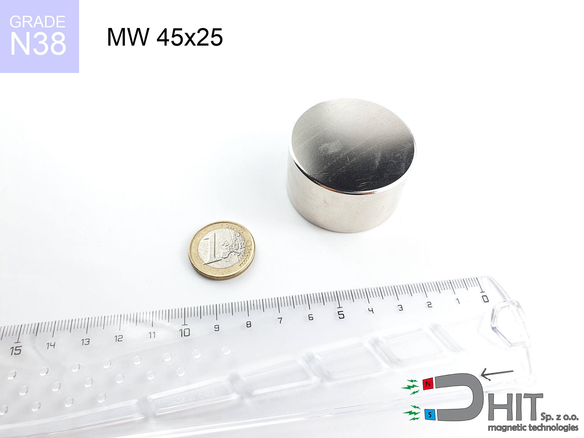
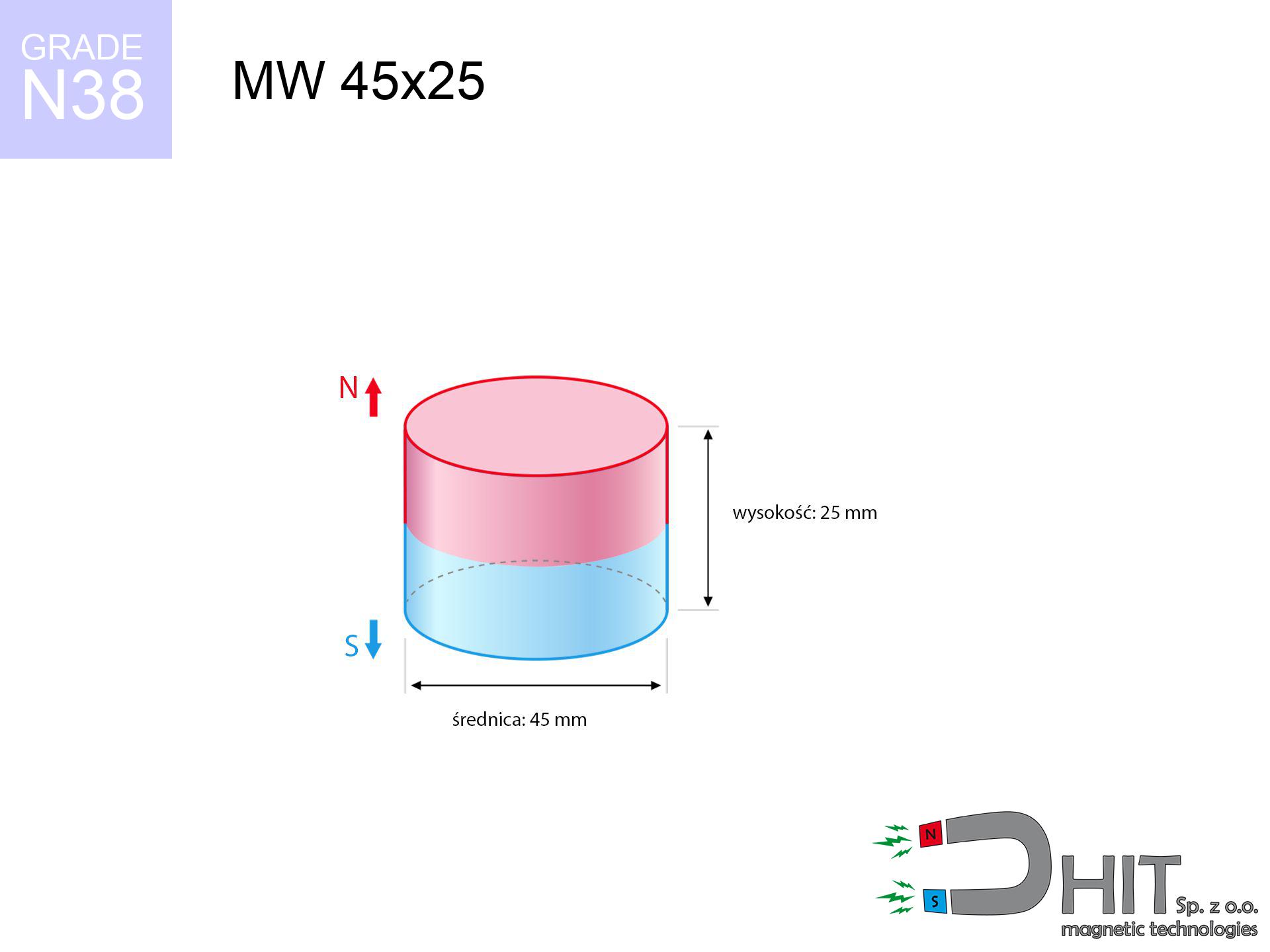
MW 45x25 / N38 - cylindrical magnet
cylindrical magnet
Catalog no 010072
GTIN/EAN: 5906301810711
- Diameter Ø
- 45 mm [±0,1 mm]
- Height
- 25 mm [±0,1 mm]
- Weight
- 298.21 g
- Magnetization Direction
- ↑ axial
- Coating
- [NiCuNi] Nickel
How we measure these parameters — certificates and measurements
82.56 zł net / pcs
101.55 zł with VAT (23% VAT) / pcs
bulk discounts:
Need more?Frequently asked questions
Where can I buy strong cylindrical neodymium magnets?
Can a small cylindrical magnet provide a strong grip for precise workshop work?
Which cylindrical magnet can work at a higher temperature?
Engineering report for this magnet
Full PDF analysis: pull and shear force, effect of distance, temperature and plate thickness, safety distances and the demagnetization curve.
Call us now
+48 888 99 98 98
alternatively let us know using
contact form
the contact section.
Specifications and structure of a neodymium magnet can be estimated using our
power calculator.
Order by 14:00 and we’ll ship today!
Technical of the product - MW 45x25 / N38 - cylindrical magnet
Specification / characteristics - MW 45x25 / N38 - cylindrical magnet
| properties | values |
|---|---|
| Cat. no. | 010072 |
| GTIN/EAN | 5906301810711 |
| Production/Distribution | Dhit sp. z o.o. |
| Country of origin | Poland / China / Germany |
| Customs code | 85059029 |
| Diameter Ø | 45 mm [±0,1 mm] |
| Height | 25 mm [±0,1 mm] |
| Weight | 298.21 g |
| Magnetization Direction | ↑ axial |
| Load capacity ~ ? | 67.33 kg / 660.28 N |
| Magnetic Induction ~ ? | 460.72 mT / 4607 Gs |
| Coating | [NiCuNi] Nickel |
| Manufacturing Tolerance | ±0.1 mm |
Magnetic properties of material N38
| properties | values | units |
|---|---|---|
| Remanence Br ? | 12.2-12.6 | kGs |
| Remanence Br ? | 1220-1260 | mT |
| Coercivity bHc ? | 10.8-11.5 | kOe |
| Coercivity bHc ? | 860-915 | kA/m |
| Intrinsic coercivity iHc | ≥ 12 | kOe |
| Intrinsic coercivity iHc | ≥ 955 | kA/m |
| Energy product BHmax ? | 36-38 | BH max MGOe |
| Energy product BHmax ? | 287-303 | BH max KJ/m |
| Maximum working temperature ? | ≤ 80 | °C |
Physical properties of sintered neodymium magnets Nd2Fe14B at 20°C
| properties | values | units |
|---|---|---|
| Vickers hardness | ≥550 | Hv |
| Density | ≥7.4 | g/cm3 |
| Curie Temperature TC | 310 | °C |
| Curie Temperature TF | 590 | °F |
| Specific resistance | 150 | μΩ⋅cm |
| Bending strength | 250 | MPa |
| Compressive strength | 1000~1100 | MPa |
| Thermal expansion parallel (∥) to orientation (M) | (3-4) x 10-6 | °C-1 |
| Thermal expansion perpendicular (⊥) to orientation (M) | -(1-3) x 10-6 | °C-1 |
| Young's modulus | 1.7 x 10⁴ | kg/mm² |
Technical simulation of the magnet - report
The following information represent the direct effect of a mathematical analysis. Values were calculated on models for the material Nd2Fe14B. Actual conditions might slightly deviate from the simulation results. Please consider these data as a supplementary guide during assembly planning.
Table 1: Static force (force vs gap) - power drop
MW 45x25 / N38
| Distance (mm) | Induction (Gauss) / mT | Pull Force (kg/lbs/g/N) | Risk Status |
|---|---|---|---|
| 0 mm |
4606 Gs
460.6 mT
|
67.33 kg / 148.44 lbs
67330.0 g / 660.5 N
|
critical level |
| 1 mm |
4413 Gs
441.3 mT
|
61.79 kg / 136.23 lbs
61791.4 g / 606.2 N
|
critical level |
| 2 mm |
4214 Gs
421.4 mT
|
56.35 kg / 124.22 lbs
56345.9 g / 552.8 N
|
critical level |
| 3 mm |
4014 Gs
401.4 mT
|
51.11 kg / 112.68 lbs
51112.0 g / 501.4 N
|
critical level |
| 5 mm |
3615 Gs
361.5 mT
|
41.47 kg / 91.42 lbs
41466.0 g / 406.8 N
|
critical level |
| 10 mm |
2697 Gs
269.7 mT
|
23.08 kg / 50.89 lbs
23083.9 g / 226.5 N
|
critical level |
| 15 mm |
1965 Gs
196.5 mT
|
12.25 kg / 27.00 lbs
12247.0 g / 120.1 N
|
critical level |
| 20 mm |
1426 Gs
142.6 mT
|
6.46 kg / 14.23 lbs
6455.7 g / 63.3 N
|
strong |
| 30 mm |
778 Gs
77.8 mT
|
1.92 kg / 4.24 lbs
1922.5 g / 18.9 N
|
weak grip |
| 50 mm |
285 Gs
28.5 mT
|
0.26 kg / 0.57 lbs
257.0 g / 2.5 N
|
weak grip |
Table 2: Sliding force (vertical surface)
MW 45x25 / N38
| Distance (mm) | Friction coefficient | Pull Force (kg/lbs/g/N) |
|---|---|---|
| 0 mm | Stal (~0.2) |
13.47 kg / 29.69 lbs
13466.0 g / 132.1 N
|
| 1 mm | Stal (~0.2) |
12.36 kg / 27.24 lbs
12358.0 g / 121.2 N
|
| 2 mm | Stal (~0.2) |
11.27 kg / 24.85 lbs
11270.0 g / 110.6 N
|
| 3 mm | Stal (~0.2) |
10.22 kg / 22.54 lbs
10222.0 g / 100.3 N
|
| 5 mm | Stal (~0.2) |
8.29 kg / 18.29 lbs
8294.0 g / 81.4 N
|
| 10 mm | Stal (~0.2) |
4.62 kg / 10.18 lbs
4616.0 g / 45.3 N
|
| 15 mm | Stal (~0.2) |
2.45 kg / 5.40 lbs
2450.0 g / 24.0 N
|
| 20 mm | Stal (~0.2) |
1.29 kg / 2.85 lbs
1292.0 g / 12.7 N
|
| 30 mm | Stal (~0.2) |
0.38 kg / 0.85 lbs
384.0 g / 3.8 N
|
| 50 mm | Stal (~0.2) |
0.05 kg / 0.11 lbs
52.0 g / 0.5 N
|
Table 3: Vertical assembly (shearing) - vertical pull
MW 45x25 / N38
| Surface type | Friction coefficient / % Mocy | Max load (kg/lbs/g/N) |
|---|---|---|
| Raw steel |
µ = 0.3
30% Nominalnej Siły
|
20.20 kg / 44.53 lbs
20199.0 g / 198.2 N
|
| Painted steel (standard) |
µ = 0.2
20% Nominalnej Siły
|
13.47 kg / 29.69 lbs
13466.0 g / 132.1 N
|
| Oily/slippery steel |
µ = 0.1
10% Nominalnej Siły
|
6.73 kg / 14.84 lbs
6733.0 g / 66.1 N
|
| Magnet with anti-slip rubber |
µ = 0.5
50% Nominalnej Siły
|
33.67 kg / 74.22 lbs
33665.0 g / 330.3 N
|
Table 4: Steel thickness (saturation) - sheet metal selection
MW 45x25 / N38
| Steel thickness (mm) | % power | Real pull force (kg/lbs/g/N) |
|---|---|---|
| 0.5 mm |
|
2.24 kg / 4.95 lbs
2244.3 g / 22.0 N
|
| 1 mm |
|
5.61 kg / 12.37 lbs
5610.8 g / 55.0 N
|
| 2 mm |
|
11.22 kg / 24.74 lbs
11221.7 g / 110.1 N
|
| 3 mm |
|
16.83 kg / 37.11 lbs
16832.5 g / 165.1 N
|
| 5 mm |
|
28.05 kg / 61.85 lbs
28054.2 g / 275.2 N
|
| 10 mm |
|
56.11 kg / 123.70 lbs
56108.3 g / 550.4 N
|
| 11 mm |
|
61.72 kg / 136.07 lbs
61719.2 g / 605.5 N
|
| 12 mm |
|
67.33 kg / 148.44 lbs
67330.0 g / 660.5 N
|
Table 5: Thermal stability (stability) - resistance threshold
MW 45x25 / N38
| Ambient temp. (°C) | Power loss | Remaining pull (kg/lbs/g/N) | Status |
|---|---|---|---|
| 20 °C | 0.0% |
67.33 kg / 148.44 lbs
67330.0 g / 660.5 N
|
OK |
| 40 °C | -2.2% |
65.85 kg / 145.17 lbs
65848.7 g / 646.0 N
|
OK |
| 60 °C | -4.4% |
64.37 kg / 141.91 lbs
64367.5 g / 631.4 N
|
OK |
| 80 °C | -6.6% |
62.89 kg / 138.64 lbs
62886.2 g / 616.9 N
|
|
| 100 °C | -28.8% |
47.94 kg / 105.69 lbs
47939.0 g / 470.3 N
|
Table 6: Two magnets (repulsion) - forces in the system
MW 45x25 / N38
| Gap (mm) | Attraction (kg/lbs) (N-S) | Sliding Force (kg/lbs/g/N) | Repulsion (kg/lbs) (N-N) |
|---|---|---|---|
| 0 mm |
208.06 kg / 458.70 lbs
5 651 Gs
|
31.21 kg / 68.80 lbs
31209 g / 306.2 N
|
N/A |
| 1 mm |
199.55 kg / 439.92 lbs
9 023 Gs
|
29.93 kg / 65.99 lbs
29932 g / 293.6 N
|
179.59 kg / 395.93 lbs
~0 Gs
|
| 2 mm |
190.95 kg / 420.96 lbs
8 826 Gs
|
28.64 kg / 63.14 lbs
28642 g / 281.0 N
|
171.85 kg / 378.87 lbs
~0 Gs
|
| 3 mm |
182.46 kg / 402.26 lbs
8 628 Gs
|
27.37 kg / 60.34 lbs
27369 g / 268.5 N
|
164.22 kg / 362.03 lbs
~0 Gs
|
| 5 mm |
165.94 kg / 365.83 lbs
8 228 Gs
|
24.89 kg / 54.87 lbs
24891 g / 244.2 N
|
149.35 kg / 329.25 lbs
~0 Gs
|
| 10 mm |
128.14 kg / 282.49 lbs
7 230 Gs
|
19.22 kg / 42.37 lbs
19221 g / 188.6 N
|
115.32 kg / 254.24 lbs
~0 Gs
|
| 20 mm |
71.33 kg / 157.26 lbs
5 394 Gs
|
10.70 kg / 23.59 lbs
10700 g / 105.0 N
|
64.20 kg / 141.54 lbs
~0 Gs
|
| 50 mm |
10.72 kg / 23.63 lbs
2 091 Gs
|
1.61 kg / 3.54 lbs
1608 g / 15.8 N
|
9.65 kg / 21.26 lbs
~0 Gs
|
| 60 mm |
5.94 kg / 13.10 lbs
1 557 Gs
|
0.89 kg / 1.96 lbs
891 g / 8.7 N
|
5.35 kg / 11.79 lbs
~0 Gs
|
| 70 mm |
3.41 kg / 7.52 lbs
1 180 Gs
|
0.51 kg / 1.13 lbs
512 g / 5.0 N
|
3.07 kg / 6.77 lbs
~0 Gs
|
| 80 mm |
2.03 kg / 4.48 lbs
910 Gs
|
0.30 kg / 0.67 lbs
305 g / 3.0 N
|
1.83 kg / 4.03 lbs
~0 Gs
|
| 90 mm |
1.25 kg / 2.76 lbs
714 Gs
|
0.19 kg / 0.41 lbs
188 g / 1.8 N
|
1.13 kg / 2.48 lbs
~0 Gs
|
| 100 mm |
0.79 kg / 1.75 lbs
569 Gs
|
0.12 kg / 0.26 lbs
119 g / 1.2 N
|
0.71 kg / 1.58 lbs
~0 Gs
|
Table 7: Hazards (implants) - precautionary measures
MW 45x25 / N38
| Object / Device | Limit (Gauss) / mT | Safe distance |
|---|---|---|
| Pacemaker | 5 Gs (0.5 mT) | 24.0 cm |
| Hearing aid | 10 Gs (1.0 mT) | 19.0 cm |
| Timepiece | 20 Gs (2.0 mT) | 14.5 cm |
| Mobile device | 40 Gs (4.0 mT) | 11.5 cm |
| Remote | 50 Gs (5.0 mT) | 10.5 cm |
| Payment card | 400 Gs (40.0 mT) | 4.5 cm |
| HDD hard drive | 600 Gs (60.0 mT) | 3.5 cm |
Table 8: Collisions (cracking risk) - collision effects
MW 45x25 / N38
| Start from (mm) | Speed (km/h) | Energy (J) | Predicted outcome |
|---|---|---|---|
| 10 mm |
19.09 km/h
(5.30 m/s)
|
4.19 J | |
| 30 mm |
22.53 km/h
(6.26 m/s)
|
5.84 J | |
| 50 mm |
22.83 km/h
(6.34 m/s)
|
6.00 J | |
| 100 mm |
22.89 km/h
(6.36 m/s)
|
6.03 J |
Table 9: Anti-corrosion coating durability
MW 45x25 / N38
| Technical parameter | Value / Description |
|---|---|
| Coating type | [NiCuNi] Nickel |
| Layer structure | Nickel - Copper - Nickel |
| Layer thickness | 10-20 µm |
| Salt spray test (SST) ? | 24 h |
| Recommended environment | Indoors only (dry) |
Table 10: Construction data (Flux)
MW 45x25 / N38
| Parameter | Value | SI Unit / Description |
|---|---|---|
| Magnetic Flux | 73 928 Mx | 739.3 µWb |
| Pc Coefficient | 0.63 | High (Stable) |
Table 11: Physics of underwater searching
MW 45x25 / N38
| Environment | Effective steel pull | Effect |
|---|---|---|
| Air (land) | 67.33 kg | Standard |
| Water (riverbed) |
77.09 kg
(+9.76 kg buoyancy gain)
|
+14.5% |
1. Shear force
*Caution: On a vertical wall, the magnet retains only ~20% of its nominal pull.
2. Plate thickness effect
*Thin metal sheet (e.g. computer case) severely weakens the holding force.
3. Temperature resistance
N38: the maximum material working temperature is 80°C. Permitted conditions also depend on the shape and magnetic circuit.
4. Demagnetization curve and operating point (B-H)
chart generated for the permeance coefficient Pc (Permeance Coefficient) = 0.63
This simulation demonstrates the magnetic stability of the selected magnet under specific geometric conditions. The solid red line represents the demagnetization curve (material potential), while the dashed blue line is the load line based on the magnet's geometry. The Pc (Permeance Coefficient), also known as the load line slope, is a dimensionless value that describes the relationship between the magnet's shape and its magnetic stability. The intersection of these two lines (the black dot) is the operating point — it determines the actual magnetic flux density generated by the magnet in this specific configuration. A higher Pc value means the magnet is more 'slender' (tall relative to its area), resulting in a higher operating point and better resistance to irreversible demagnetization caused by external fields or temperature. A value of 0.42 is relatively low (typical for flat magnets), meaning the operating point is closer to the 'knee' of the curve — caution is advised when operating at temperatures near the maximum limit to avoid strength loss.
Material specification
| iron (Fe) | 64% – 68% |
| neodymium (Nd) | 29% – 32% |
| boron (B) | 1.1% – 1.2% |
| dysprosium (Dy) | 0.5% – 2.0% |
| coating (Ni-Cu-Ni) | < 0.05% |
Environmental data
| recyclability (EoL) | 100% |
| recycled raw materials | ~10% (pre-cons) |
| carbon footprint | low / zredukowany |
| waste code (EWC) | 16 02 16 |
Other proposals


Pros as well as cons of Nd2Fe14B magnets.
Advantages
- They do not lose magnetism, even after nearly 10 years – the decrease in lifting capacity is only ~1% (based on measurements),
- They feature excellent resistance to magnetic field loss as a result of external fields,
- By using a smooth coating of nickel, the element presents an proper look,
- Magnets have extremely high magnetic induction on the outer side,
- Neodymium magnets are characterized by very high magnetic induction on the magnet surface and can function (depending on the form) even at a temperature of 230°C or more...
- Possibility of detailed machining as well as adapting to defined applications,
- Huge importance in high-tech industry – they are used in computer drives, brushless drives, medical equipment, also technologically advanced constructions.
- Relatively small size with high pulling force – neodymium magnets offer high power in small dimensions, which enables their usage in miniature devices
Cons
- They are fragile upon too strong impacts. To avoid cracks, it is worth protecting magnets using a steel holder. Such protection not only shields the magnet but also improves its resistance to damage
- Do not exceed this material temperature limit: 80°C. Overheating may permanently weaken the magnet.
- When exposed to humidity, magnets usually rust. To use them in conditions outside, it is recommended to use protective magnets, such as magnets in rubber or plastics, which prevent oxidation and corrosion.
- We recommend a housing - magnetic mechanism, due to difficulties in producing nuts inside the magnet and complicated forms.
- Health risk to health – tiny shards of magnets pose a threat, in case of ingestion, which becomes key in the aspect of protecting the youngest. It is also worth noting that small elements of these products can complicate diagnosis medical in case of swallowing.
- With large orders the cost of neodymium magnets is a challenge,
Holding force characteristics
Maximum lifting capacity of the magnet – what affects it?
- with the use of a sheet made of special test steel, guaranteeing full magnetic saturation
- with a cross-section of at least 10 mm
- with an ground touching surface
- without the slightest clearance between the magnet and steel
- during detachment in a direction vertical to the plane
- at conditions approx. 20°C
Magnet lifting force in use – key factors
- Space between magnet and steel – every millimeter of separation (caused e.g. by varnish or dirt) diminishes the magnet efficiency, often by half at just 0.5 mm.
- Load vector – highest force is available only during perpendicular pulling. The shear force of the magnet along the surface is standardly several times lower (approx. 1/5 of the lifting capacity).
- Metal thickness – thin material does not allow full use of the magnet. Magnetic flux penetrates through instead of generating force.
- Chemical composition of the base – mild steel attracts best. Alloy steels decrease magnetic permeability and lifting capacity.
- Surface finish – full contact is possible only on polished steel. Rough texture create air cushions, weakening the magnet.
- Temperature – temperature increase results in weakening of induction. It is worth remembering the maximum operating temperature for a given model.
Lifting capacity testing was conducted on a smooth plate of suitable thickness, under perpendicular forces, however under parallel forces the lifting capacity is smaller. Moreover, even a minimal clearance between the magnet’s surface and the plate decreases the holding force.
Safe handling of NdFeB magnets
Operating temperature
Avoid heat. NdFeB magnets are susceptible to temperature. If you require operation above 80°C, ask us about HT versions (H, SH, UH).
Shattering risk
Watch out for shards. Magnets can fracture upon uncontrolled impact, launching shards into the air. We recommend safety glasses.
Physical harm
Watch your fingers. Two powerful magnets will snap together immediately with a force of massive weight, crushing anything in their path. Be careful!
Electronic devices
Equipment safety: Strong magnets can damage data carriers and sensitive devices (pacemakers, medical aids, timepieces).
Handling rules
Be careful. Rare earth magnets act from a long distance and snap with massive power, often quicker than you can react.
Warning for allergy sufferers
Warning for allergy sufferers: The nickel-copper-nickel coating contains nickel. If skin irritation appears, cease working with magnets and use protective gear.
Implant safety
Patients with a heart stimulator should keep an safe separation from magnets. The magnetic field can disrupt the operation of the implant.
Keep away from children
Product intended for adults. Tiny parts can be swallowed, causing serious injuries. Store away from children and animals.
Dust explosion hazard
Machining of neodymium magnets carries a risk of fire hazard. Neodymium dust oxidizes rapidly with oxygen and is difficult to extinguish.
Precision electronics
Remember: neodymium magnets generate a field that interferes with sensitive sensors. Maintain a separation from your phone, tablet, and GPS.
Tabela kosztu i czasu dostawy
Płatność przed wysyłką:

GLS kurier
Przesyłka będzie u Ciebie za 2-3 dni
14.99 ZŁ

InPost Paczkomaty 24/7
Przesyłka będzie u Ciebie za 1-2 dni
12.30 ZŁ
Płatność przy odbiorze (pobranie):
GLS kurier
Przesyłka będzie u Ciebie za 1-2 dni
23.00 ZŁ