


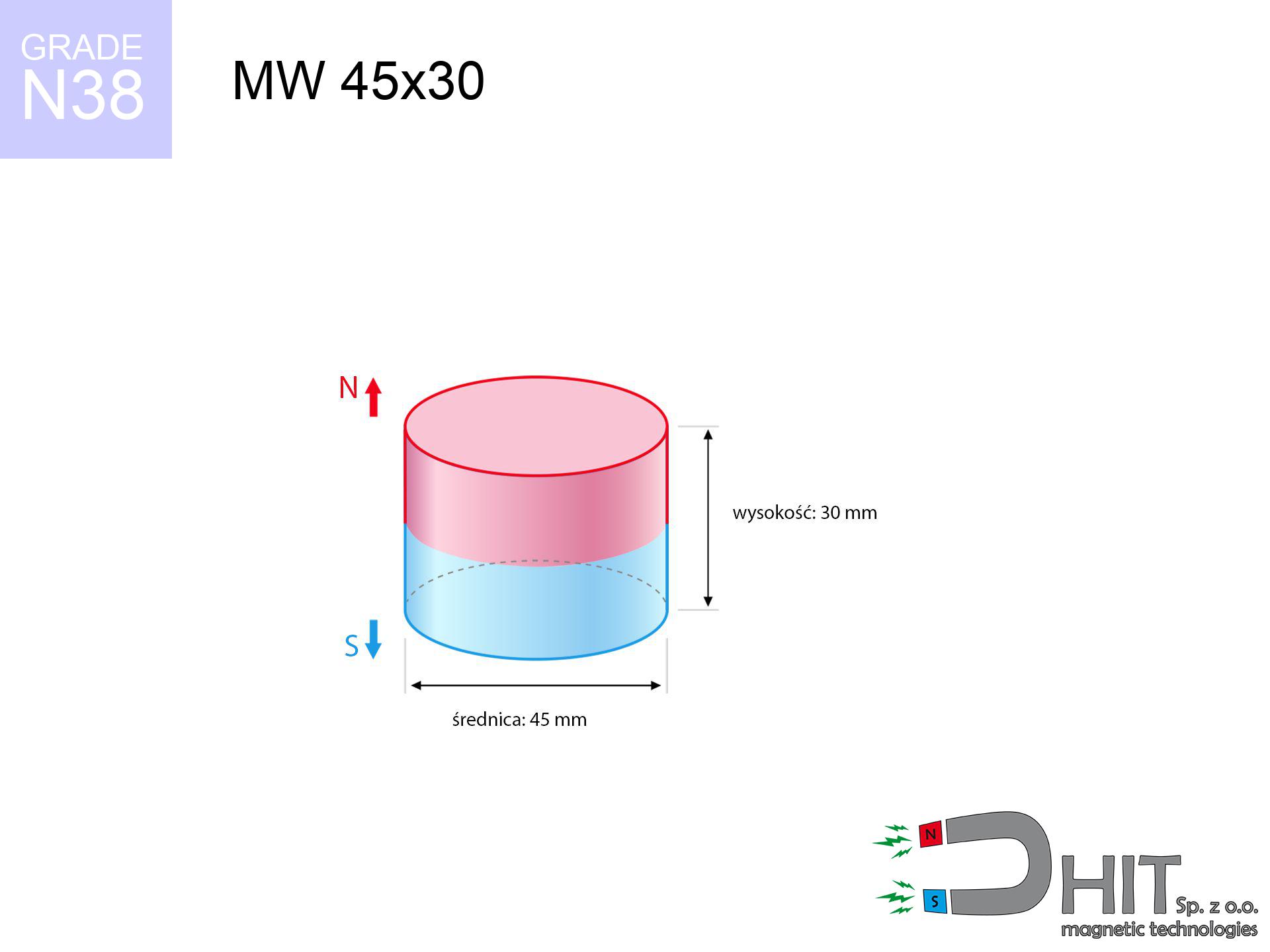
MW 45x30 / N38 - cylindrical magnet
cylindrical magnet
Catalog no 010073
GTIN/EAN: 5906301810728
- Diameter Ø
- 45 mm [±0,1 mm]
- Height
- 30 mm [±0,1 mm]
- Weight
- 357.85 g
- Magnetization Direction
- ↑ axial
- Coating
- [NiCuNi] Nickel
How we measure these parameters — certificates and measurements
111.22 zł net / pcs
136.80 zł with VAT (23% VAT) / pcs
bulk discounts:
Need more?Frequently asked questions
Where can I buy strong cylindrical neodymium magnets?
Can a small cylindrical magnet provide a strong grip for precise workshop work?
Which cylindrical magnet can work at a higher temperature?
Engineering report for this magnet
Full PDF analysis: pull and shear force, effect of distance, temperature and plate thickness, safety distances and the demagnetization curve.
Call us now
+48 888 99 98 98
alternatively let us know using
contact form
the contact section.
Specifications and structure of a neodymium magnet can be estimated using our
power calculator.
Order by 14:00 and we’ll ship today!
Technical - MW 45x30 / N38 - cylindrical magnet
Specification / characteristics - MW 45x30 / N38 - cylindrical magnet
| properties | values |
|---|---|
| Cat. no. | 010073 |
| GTIN/EAN | 5906301810728 |
| Production/Distribution | Dhit sp. z o.o. |
| Country of origin | Poland / China / Germany |
| Customs code | 85059029 |
| Diameter Ø | 45 mm [±0,1 mm] |
| Height | 30 mm [±0,1 mm] |
| Weight | 357.85 g |
| Magnetization Direction | ↑ axial |
| Load capacity ~ ? | 69.46 kg / 681.39 N |
| Magnetic Induction ~ ? | 495.87 mT / 4959 Gs |
| Coating | [NiCuNi] Nickel |
| Manufacturing Tolerance | ±0.1 mm |
Magnetic properties of material N38
| properties | values | units |
|---|---|---|
| Remanence Br ? | 12.2-12.6 | kGs |
| Remanence Br ? | 1220-1260 | mT |
| Coercivity bHc ? | 10.8-11.5 | kOe |
| Coercivity bHc ? | 860-915 | kA/m |
| Intrinsic coercivity iHc | ≥ 12 | kOe |
| Intrinsic coercivity iHc | ≥ 955 | kA/m |
| Energy product BHmax ? | 36-38 | BH max MGOe |
| Energy product BHmax ? | 287-303 | BH max KJ/m |
| Maximum working temperature ? | ≤ 80 | °C |
Physical properties of sintered neodymium magnets Nd2Fe14B at 20°C
| properties | values | units |
|---|---|---|
| Vickers hardness | ≥550 | Hv |
| Density | ≥7.4 | g/cm3 |
| Curie Temperature TC | 310 | °C |
| Curie Temperature TF | 590 | °F |
| Specific resistance | 150 | μΩ⋅cm |
| Bending strength | 250 | MPa |
| Compressive strength | 1000~1100 | MPa |
| Thermal expansion parallel (∥) to orientation (M) | (3-4) x 10-6 | °C-1 |
| Thermal expansion perpendicular (⊥) to orientation (M) | -(1-3) x 10-6 | °C-1 |
| Young's modulus | 1.7 x 10⁴ | kg/mm² |
Technical modeling of the magnet - report
Presented data constitute the result of a engineering simulation. Values were calculated on algorithms for the material Nd2Fe14B. Real-world parameters may differ. Treat these calculations as a preliminary roadmap when designing systems.
Table 1: Static pull force (force vs gap) - characteristics
MW 45x30 / N38
| Distance (mm) | Induction (Gauss) / mT | Pull Force (kg/lbs/g/N) | Risk Status |
|---|---|---|---|
| 0 mm |
4958 Gs
495.8 mT
|
69.46 kg / 153.13 lbs
69460.0 g / 681.4 N
|
critical level |
| 1 mm |
4742 Gs
474.2 mT
|
63.55 kg / 140.11 lbs
63553.9 g / 623.5 N
|
critical level |
| 2 mm |
4523 Gs
452.3 mT
|
57.81 kg / 127.44 lbs
57805.8 g / 567.1 N
|
critical level |
| 3 mm |
4303 Gs
430.3 mT
|
52.33 kg / 115.36 lbs
52327.7 g / 513.3 N
|
critical level |
| 5 mm |
3870 Gs
387.0 mT
|
42.33 kg / 93.32 lbs
42329.9 g / 415.3 N
|
critical level |
| 10 mm |
2886 Gs
288.6 mT
|
23.53 kg / 51.88 lbs
23531.8 g / 230.8 N
|
critical level |
| 15 mm |
2106 Gs
210.6 mT
|
12.54 kg / 27.64 lbs
12537.0 g / 123.0 N
|
critical level |
| 20 mm |
1535 Gs
153.5 mT
|
6.66 kg / 14.68 lbs
6657.1 g / 65.3 N
|
medium risk |
| 30 mm |
845 Gs
84.5 mT
|
2.02 kg / 4.45 lbs
2018.9 g / 19.8 N
|
medium risk |
| 50 mm |
315 Gs
31.5 mT
|
0.28 kg / 0.62 lbs
279.5 g / 2.7 N
|
safe |
Table 2: Slippage capacity (vertical surface)
MW 45x30 / N38
| Distance (mm) | Friction coefficient | Pull Force (kg/lbs/g/N) |
|---|---|---|
| 0 mm | Stal (~0.2) |
13.89 kg / 30.63 lbs
13892.0 g / 136.3 N
|
| 1 mm | Stal (~0.2) |
12.71 kg / 28.02 lbs
12710.0 g / 124.7 N
|
| 2 mm | Stal (~0.2) |
11.56 kg / 25.49 lbs
11562.0 g / 113.4 N
|
| 3 mm | Stal (~0.2) |
10.47 kg / 23.07 lbs
10466.0 g / 102.7 N
|
| 5 mm | Stal (~0.2) |
8.47 kg / 18.66 lbs
8466.0 g / 83.1 N
|
| 10 mm | Stal (~0.2) |
4.71 kg / 10.37 lbs
4706.0 g / 46.2 N
|
| 15 mm | Stal (~0.2) |
2.51 kg / 5.53 lbs
2508.0 g / 24.6 N
|
| 20 mm | Stal (~0.2) |
1.33 kg / 2.94 lbs
1332.0 g / 13.1 N
|
| 30 mm | Stal (~0.2) |
0.40 kg / 0.89 lbs
404.0 g / 4.0 N
|
| 50 mm | Stal (~0.2) |
0.06 kg / 0.12 lbs
56.0 g / 0.5 N
|
Table 3: Wall mounting (sliding) - behavior on slippery surfaces
MW 45x30 / N38
| Surface type | Friction coefficient / % Mocy | Max load (kg/lbs/g/N) |
|---|---|---|
| Raw steel |
µ = 0.3
30% Nominalnej Siły
|
20.84 kg / 45.94 lbs
20838.0 g / 204.4 N
|
| Painted steel (standard) |
µ = 0.2
20% Nominalnej Siły
|
13.89 kg / 30.63 lbs
13892.0 g / 136.3 N
|
| Oily/slippery steel |
µ = 0.1
10% Nominalnej Siły
|
6.95 kg / 15.31 lbs
6946.0 g / 68.1 N
|
| Magnet with anti-slip rubber |
µ = 0.5
50% Nominalnej Siły
|
34.73 kg / 76.57 lbs
34730.0 g / 340.7 N
|
Table 4: Steel thickness (saturation) - power losses
MW 45x30 / N38
| Steel thickness (mm) | % power | Real pull force (kg/lbs/g/N) |
|---|---|---|
| 0.5 mm |
|
2.32 kg / 5.10 lbs
2315.3 g / 22.7 N
|
| 1 mm |
|
5.79 kg / 12.76 lbs
5788.3 g / 56.8 N
|
| 2 mm |
|
11.58 kg / 25.52 lbs
11576.7 g / 113.6 N
|
| 3 mm |
|
17.37 kg / 38.28 lbs
17365.0 g / 170.4 N
|
| 5 mm |
|
28.94 kg / 63.81 lbs
28941.7 g / 283.9 N
|
| 10 mm |
|
57.88 kg / 127.61 lbs
57883.3 g / 567.8 N
|
| 11 mm |
|
63.67 kg / 140.37 lbs
63671.7 g / 624.6 N
|
| 12 mm |
|
69.46 kg / 153.13 lbs
69460.0 g / 681.4 N
|
Table 5: Thermal resistance (material behavior) - thermal limit
MW 45x30 / N38
| Ambient temp. (°C) | Power loss | Remaining pull (kg/lbs/g/N) | Status |
|---|---|---|---|
| 20 °C | 0.0% |
69.46 kg / 153.13 lbs
69460.0 g / 681.4 N
|
OK |
| 40 °C | -2.2% |
67.93 kg / 149.76 lbs
67931.9 g / 666.4 N
|
OK |
| 60 °C | -4.4% |
66.40 kg / 146.40 lbs
66403.8 g / 651.4 N
|
OK |
| 80 °C | -6.6% |
64.88 kg / 143.03 lbs
64875.6 g / 636.4 N
|
|
| 100 °C | -28.8% |
49.46 kg / 109.03 lbs
49455.5 g / 485.2 N
|
Table 6: Magnet-Magnet interaction (repulsion) - forces in the system
MW 45x30 / N38
| Gap (mm) | Attraction (kg/lbs) (N-S) | Lateral Force (kg/lbs/g/N) | Repulsion (kg/lbs) (N-N) |
|---|---|---|---|
| 0 mm |
241.01 kg / 531.33 lbs
5 803 Gs
|
36.15 kg / 79.70 lbs
36151 g / 354.6 N
|
N/A |
| 1 mm |
230.79 kg / 508.80 lbs
9 703 Gs
|
34.62 kg / 76.32 lbs
34618 g / 339.6 N
|
207.71 kg / 457.92 lbs
~0 Gs
|
| 2 mm |
220.52 kg / 486.16 lbs
9 485 Gs
|
33.08 kg / 72.92 lbs
33078 g / 324.5 N
|
198.47 kg / 437.54 lbs
~0 Gs
|
| 3 mm |
210.44 kg / 463.94 lbs
9 265 Gs
|
31.57 kg / 69.59 lbs
31566 g / 309.7 N
|
189.39 kg / 417.54 lbs
~0 Gs
|
| 5 mm |
190.94 kg / 420.95 lbs
8 826 Gs
|
28.64 kg / 63.14 lbs
28641 g / 281.0 N
|
171.85 kg / 378.86 lbs
~0 Gs
|
| 10 mm |
146.87 kg / 323.80 lbs
7 741 Gs
|
22.03 kg / 48.57 lbs
22031 g / 216.1 N
|
132.19 kg / 291.42 lbs
~0 Gs
|
| 20 mm |
81.65 kg / 180.01 lbs
5 771 Gs
|
12.25 kg / 27.00 lbs
12247 g / 120.1 N
|
73.48 kg / 162.01 lbs
~0 Gs
|
| 50 mm |
12.52 kg / 27.60 lbs
2 260 Gs
|
1.88 kg / 4.14 lbs
1878 g / 18.4 N
|
11.27 kg / 24.84 lbs
~0 Gs
|
| 60 mm |
7.01 kg / 15.44 lbs
1 690 Gs
|
1.05 kg / 2.32 lbs
1051 g / 10.3 N
|
6.30 kg / 13.90 lbs
~0 Gs
|
| 70 mm |
4.06 kg / 8.95 lbs
1 287 Gs
|
0.61 kg / 1.34 lbs
609 g / 6.0 N
|
3.66 kg / 8.06 lbs
~0 Gs
|
| 80 mm |
2.44 kg / 5.38 lbs
998 Gs
|
0.37 kg / 0.81 lbs
366 g / 3.6 N
|
2.20 kg / 4.84 lbs
~0 Gs
|
| 90 mm |
1.51 kg / 3.34 lbs
786 Gs
|
0.23 kg / 0.50 lbs
227 g / 2.2 N
|
1.36 kg / 3.01 lbs
~0 Gs
|
| 100 mm |
0.97 kg / 2.14 lbs
629 Gs
|
0.15 kg / 0.32 lbs
145 g / 1.4 N
|
0.87 kg / 1.92 lbs
~0 Gs
|
Table 7: Protective zones (electronics) - precautionary measures
MW 45x30 / N38
| Object / Device | Limit (Gauss) / mT | Safe distance |
|---|---|---|
| Pacemaker | 5 Gs (0.5 mT) | 25.5 cm |
| Hearing aid | 10 Gs (1.0 mT) | 20.0 cm |
| Timepiece | 20 Gs (2.0 mT) | 15.5 cm |
| Phone / Smartphone | 40 Gs (4.0 mT) | 12.0 cm |
| Car key | 50 Gs (5.0 mT) | 11.0 cm |
| Payment card | 400 Gs (40.0 mT) | 4.5 cm |
| HDD hard drive | 600 Gs (60.0 mT) | 4.0 cm |
Table 8: Dynamics (kinetic energy) - warning
MW 45x30 / N38
| Start from (mm) | Speed (km/h) | Energy (J) | Predicted outcome |
|---|---|---|---|
| 10 mm |
17.63 km/h
(4.90 m/s)
|
4.29 J | |
| 30 mm |
20.82 km/h
(5.78 m/s)
|
5.98 J | |
| 50 mm |
21.10 km/h
(5.86 m/s)
|
6.15 J | |
| 100 mm |
21.17 km/h
(5.88 m/s)
|
6.18 J |
Table 9: Surface protection spec
MW 45x30 / N38
| Technical parameter | Value / Description |
|---|---|
| Coating type | [NiCuNi] Nickel |
| Layer structure | Nickel - Copper - Nickel |
| Layer thickness | 10-20 µm |
| Salt spray test (SST) ? | 24 h |
| Recommended environment | Indoors only (dry) |
Table 10: Construction data (Pc)
MW 45x30 / N38
| Parameter | Value | SI Unit / Description |
|---|---|---|
| Magnetic Flux | 79 446 Mx | 794.5 µWb |
| Pc Coefficient | 0.71 | High (Stable) |
Table 11: Submerged application
MW 45x30 / N38
| Environment | Effective steel pull | Effect |
|---|---|---|
| Air (land) | 69.46 kg | Standard |
| Water (riverbed) |
79.53 kg
(+10.07 kg buoyancy gain)
|
+14.5% |
1. Sliding resistance
*Note: On a vertical surface, the magnet holds merely a fraction of its nominal pull.
2. Steel saturation
*Thin steel (e.g. 0.5mm PC case) significantly limits the holding force.
3. Temperature resistance
N38: the maximum material working temperature is 80°C. Permitted conditions also depend on the shape and magnetic circuit.
4. Demagnetization curve and operating point (B-H)
chart generated for the permeance coefficient Pc (Permeance Coefficient) = 0.71
This simulation demonstrates the magnetic stability of the selected magnet under specific geometric conditions. The solid red line represents the demagnetization curve (material potential), while the dashed blue line is the load line based on the magnet's geometry. The Pc (Permeance Coefficient), also known as the load line slope, is a dimensionless value that describes the relationship between the magnet's shape and its magnetic stability. The intersection of these two lines (the black dot) is the operating point — it determines the actual magnetic flux density generated by the magnet in this specific configuration. A higher Pc value means the magnet is more 'slender' (tall relative to its area), resulting in a higher operating point and better resistance to irreversible demagnetization caused by external fields or temperature. A value of 0.42 is relatively low (typical for flat magnets), meaning the operating point is closer to the 'knee' of the curve — caution is advised when operating at temperatures near the maximum limit to avoid strength loss.
Chemical composition
| iron (Fe) | 64% – 68% |
| neodymium (Nd) | 29% – 32% |
| boron (B) | 1.1% – 1.2% |
| dysprosium (Dy) | 0.5% – 2.0% |
| coating (Ni-Cu-Ni) | < 0.05% |
Sustainability
| recyclability (EoL) | 100% |
| recycled raw materials | ~10% (pre-cons) |
| carbon footprint | low / zredukowany |
| waste code (EWC) | 16 02 16 |
See more offers

![UMGGW 66x8.5 [M8] GW / N38 - magnetic holder rubber internal thread](https://cdn3.dhit.pl/graphics/products/umg-66x8.5-m6-gw-wud.jpg "UMGGW 66x8.5 [M8] GW / N38 - magnetic holder rubber internal thread")
Advantages as well as disadvantages of rare earth magnets.
Pros
- They retain magnetic properties for almost 10 years – the loss is just ~1% (based on simulations),
- Magnets effectively protect themselves against demagnetization caused by ambient magnetic noise,
- A magnet with a metallic gold surface has an effective appearance,
- Magnetic induction on the working part of the magnet remains impressive,
- Thanks to resistance to high temperature, they are able to function (depending on the form) even at temperatures up to 230°C and higher...
- Thanks to flexibility in constructing and the ability to customize to specific needs,
- Significant place in future technologies – they find application in hard drives, motor assemblies, medical devices, also other advanced devices.
- Relatively small size with high pulling force – neodymium magnets offer strong magnetic field in small dimensions, which enables their usage in compact constructions
Limitations
- Brittleness is one of their disadvantages. Upon intense impact they can break. We recommend keeping them in a special holder, which not only secures them against impacts but also raises their durability
- Do not exceed this material temperature limit: 80°C. Overheating may permanently weaken the magnet.
- They oxidize in a humid environment. For use outdoors we suggest using waterproof magnets e.g. in rubber, plastic
- Limited possibility of making threads in the magnet and complex shapes - recommended is casing - mounting mechanism.
- Health risk resulting from small fragments of magnets are risky, when accidentally swallowed, which gains importance in the aspect of protecting the youngest. It is also worth noting that small elements of these magnets can disrupt the diagnostic process medical in case of swallowing.
- High unit price – neodymium magnets cost more than other types of magnets (e.g. ferrite), which increases costs of application in large quantities
Pull force analysis
Optimal lifting capacity of a neodymium magnet – what it depends on?
- with the contact of a sheet made of low-carbon steel, ensuring maximum field concentration
- with a cross-section minimum 10 mm
- characterized by smoothness
- with zero gap (no paint)
- during pulling in a direction perpendicular to the mounting surface
- in neutral thermal conditions
Determinants of practical lifting force of a magnet
- Distance (betwixt the magnet and the metal), as even a tiny clearance (e.g. 0.5 mm) can cause a reduction in force by up to 50% (this also applies to varnish, rust or debris).
- Force direction – catalog parameter refers to detachment vertically. When slipping, the magnet holds much less (typically approx. 20-30% of nominal force).
- Element thickness – to utilize 100% power, the steel must be adequately massive. Thin sheet limits the attraction force (the magnet "punches through" it).
- Material type – ideal substrate is pure iron steel. Hardened steels may have worse magnetic properties.
- Plate texture – smooth surfaces guarantee perfect abutment, which increases force. Rough surfaces reduce efficiency.
- Thermal environment – heating the magnet causes a temporary drop of force. Check the thermal limit for a given model.
Lifting capacity testing was conducted on plates with a smooth surface of suitable thickness, under perpendicular forces, in contrast under parallel forces the load capacity is reduced by as much as 5 times. Moreover, even a small distance between the magnet’s surface and the plate reduces the lifting capacity.
H&S for magnets
Pacemakers
People with a heart stimulator must maintain an large gap from magnets. The magnetism can interfere with the operation of the life-saving device.
Handling guide
Before starting, read the rules. Sudden snapping can break the magnet or injure your hand. Think ahead.
Fire warning
Fire warning: Rare earth powder is explosive. Do not process magnets without safety gear as this risks ignition.
Threat to electronics
Powerful magnetic fields can destroy records on payment cards, HDDs, and other magnetic media. Stay away of min. 10 cm.
Allergic reactions
Some people have a sensitization to Ni, which is the typical protective layer for neodymium magnets. Prolonged contact might lead to dermatitis. We strongly advise wear safety gloves.
GPS Danger
A powerful magnetic field negatively affects the functioning of compasses in smartphones and GPS navigation. Do not bring magnets near a smartphone to prevent damaging the sensors.
Crushing force
Danger of trauma: The attraction force is so immense that it can result in hematomas, pinching, and broken bones. Protective gloves are recommended.
Operating temperature
Control the heat. Heating the magnet to high heat will destroy its magnetic structure and strength.
Fragile material
Despite the nickel coating, the material is brittle and cannot withstand shocks. Avoid impacts, as the magnet may shatter into hazardous fragments.
Adults only
NdFeB magnets are not intended for children. Accidental ingestion of a few magnets can lead to them pinching intestinal walls, which poses a direct threat to life and necessitates immediate surgery.
Tabela kosztu i czasu dostawy
Płatność przed wysyłką:

GLS kurier
Przesyłka będzie u Ciebie za 2-3 dni
14.99 ZŁ

InPost Paczkomaty 24/7
Przesyłka będzie u Ciebie za 1-2 dni
12.30 ZŁ
Płatność przy odbiorze (pobranie):
GLS kurier
Przesyłka będzie u Ciebie za 1-2 dni
23.00 ZŁ