

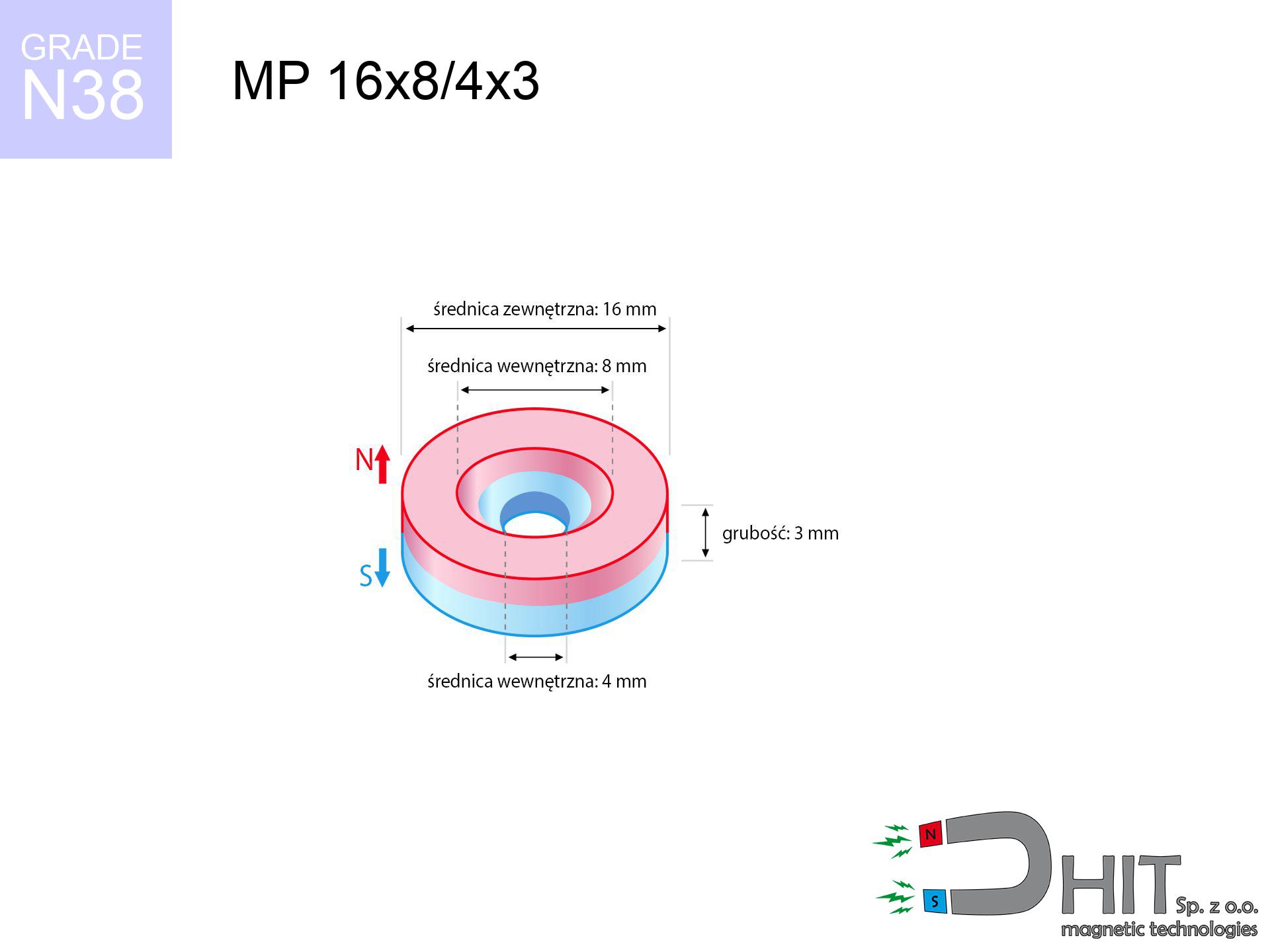
MP 16x8/4x3 / N38 - ring magnet
ring magnet
Catalog no 030396
GTIN/EAN: 5906301812333
- Diameter
- 16 mm [±0,1 mm]
- internal diameter Ø
- 8/4 mm [±0,1 mm]
- Height
- 3 mm [±0,1 mm]
- Weight
- 4.24 g
- Magnetization Direction
- ↑ axial
- Coating
- [NiCuNi] Nickel
How we measure these parameters — certificates and measurements
2.03 zł net / pcs
2.50 zł with VAT (23% VAT) / pcs
bulk discounts:
Need more?Frequently asked questions
Where can I compare prices of ring magnets for mounting in Poland?
Are ring magnets resistant to damage?
Which ring magnet is suitable for an outdoor structure?
Where can I check the available sizes of neodymium ring magnets?
Engineering report for this magnet
Full PDF analysis: pull and shear force, effect of distance, temperature and plate thickness, safety distances and the demagnetization curve.
Call us now
+48 888 99 98 98
alternatively let us know using
contact form
the contact section.
Specifications and structure of a neodymium magnet can be estimated using our
power calculator.
Order by 14:00 and we’ll ship today!
Product card - MP 16x8/4x3 / N38 - ring magnet
Specification / characteristics - MP 16x8/4x3 / N38 - ring magnet
| properties | values |
|---|---|
| Cat. no. | 030396 |
| GTIN/EAN | 5906301812333 |
| Production/Distribution | Dhit sp. z o.o. |
| Country of origin | Poland / China / Germany |
| Customs code | 85059029 |
| Diameter | 16 mm [±0,1 mm] |
| internal diameter Ø | 8/4 mm [±0,1 mm] |
| Height | 3 mm [±0,1 mm] |
| Weight | 4.24 g |
| Magnetization Direction | ↑ axial |
| Load capacity ~ ? | 2.78 kg / 27.29 N |
| Magnetic Induction ~ ? | 217.61 mT / 2176 Gs |
| Coating | [NiCuNi] Nickel |
| Manufacturing Tolerance | ±0.1 mm |
Magnetic properties of material N38
| properties | values | units |
|---|---|---|
| Remanence Br ? | 12.2-12.6 | kGs |
| Remanence Br ? | 1220-1260 | mT |
| Coercivity bHc ? | 10.8-11.5 | kOe |
| Coercivity bHc ? | 860-915 | kA/m |
| Intrinsic coercivity iHc | ≥ 12 | kOe |
| Intrinsic coercivity iHc | ≥ 955 | kA/m |
| Energy product BHmax ? | 36-38 | BH max MGOe |
| Energy product BHmax ? | 287-303 | BH max KJ/m |
| Maximum working temperature ? | ≤ 80 | °C |
Physical properties of sintered neodymium magnets Nd2Fe14B at 20°C
| properties | values | units |
|---|---|---|
| Vickers hardness | ≥550 | Hv |
| Density | ≥7.4 | g/cm3 |
| Curie Temperature TC | 310 | °C |
| Curie Temperature TF | 590 | °F |
| Specific resistance | 150 | μΩ⋅cm |
| Bending strength | 250 | MPa |
| Compressive strength | 1000~1100 | MPa |
| Thermal expansion parallel (∥) to orientation (M) | (3-4) x 10-6 | °C-1 |
| Thermal expansion perpendicular (⊥) to orientation (M) | -(1-3) x 10-6 | °C-1 |
| Young's modulus | 1.7 x 10⁴ | kg/mm² |
Physical simulation of the product - data
Presented values constitute the outcome of a engineering calculation. Results are based on algorithms for the material Nd2Fe14B. Operational performance may differ. Use these calculations as a supplementary guide for designers.
Table 1: Static pull force (pull vs distance) - power drop
MP 16x8/4x3 / N38
| Distance (mm) | Induction (Gauss) / mT | Pull Force (kg/lbs/g/N) | Risk Status |
|---|---|---|---|
| 0 mm |
1882 Gs
188.2 mT
|
2.78 kg / 6.13 LBS
2780.0 g / 27.3 N
|
strong |
| 1 mm |
1746 Gs
174.6 mT
|
2.39 kg / 5.27 LBS
2392.4 g / 23.5 N
|
strong |
| 2 mm |
1561 Gs
156.1 mT
|
1.91 kg / 4.22 LBS
1913.9 g / 18.8 N
|
safe |
| 3 mm |
1357 Gs
135.7 mT
|
1.45 kg / 3.19 LBS
1445.8 g / 14.2 N
|
safe |
| 5 mm |
969 Gs
96.9 mT
|
0.74 kg / 1.63 LBS
737.7 g / 7.2 N
|
safe |
| 10 mm |
387 Gs
38.7 mT
|
0.12 kg / 0.26 LBS
117.4 g / 1.2 N
|
safe |
| 15 mm |
171 Gs
17.1 mT
|
0.02 kg / 0.05 LBS
22.9 g / 0.2 N
|
safe |
| 20 mm |
87 Gs
8.7 mT
|
0.01 kg / 0.01 LBS
5.9 g / 0.1 N
|
safe |
| 30 mm |
30 Gs
3.0 mT
|
0.00 kg / 0.00 LBS
0.7 g / 0.0 N
|
safe |
| 50 mm |
7 Gs
0.7 mT
|
0.00 kg / 0.00 LBS
0.0 g / 0.0 N
|
safe |
Table 2: Shear capacity (vertical surface)
MP 16x8/4x3 / N38
| Distance (mm) | Friction coefficient | Pull Force (kg/lbs/g/N) |
|---|---|---|
| 0 mm | Stal (~0.2) |
0.56 kg / 1.23 LBS
556.0 g / 5.5 N
|
| 1 mm | Stal (~0.2) |
0.48 kg / 1.05 LBS
478.0 g / 4.7 N
|
| 2 mm | Stal (~0.2) |
0.38 kg / 0.84 LBS
382.0 g / 3.7 N
|
| 3 mm | Stal (~0.2) |
0.29 kg / 0.64 LBS
290.0 g / 2.8 N
|
| 5 mm | Stal (~0.2) |
0.15 kg / 0.33 LBS
148.0 g / 1.5 N
|
| 10 mm | Stal (~0.2) |
0.02 kg / 0.05 LBS
24.0 g / 0.2 N
|
| 15 mm | Stal (~0.2) |
0.00 kg / 0.01 LBS
4.0 g / 0.0 N
|
| 20 mm | Stal (~0.2) |
0.00 kg / 0.00 LBS
2.0 g / 0.0 N
|
| 30 mm | Stal (~0.2) |
0.00 kg / 0.00 LBS
0.0 g / 0.0 N
|
| 50 mm | Stal (~0.2) |
0.00 kg / 0.00 LBS
0.0 g / 0.0 N
|
Table 3: Wall mounting (shearing) - vertical pull
MP 16x8/4x3 / N38
| Surface type | Friction coefficient / % Mocy | Max load (kg/lbs/g/N) |
|---|---|---|
| Raw steel |
µ = 0.3
30% Nominalnej Siły
|
0.83 kg / 1.84 LBS
834.0 g / 8.2 N
|
| Painted steel (standard) |
µ = 0.2
20% Nominalnej Siły
|
0.56 kg / 1.23 LBS
556.0 g / 5.5 N
|
| Oily/slippery steel |
µ = 0.1
10% Nominalnej Siły
|
0.28 kg / 0.61 LBS
278.0 g / 2.7 N
|
| Magnet with anti-slip rubber |
µ = 0.5
50% Nominalnej Siły
|
1.39 kg / 3.06 LBS
1390.0 g / 13.6 N
|
Table 4: Material efficiency (saturation) - power losses
MP 16x8/4x3 / N38
| Steel thickness (mm) | % power | Real pull force (kg/lbs/g/N) |
|---|---|---|
| 0.5 mm |
|
0.28 kg / 0.61 LBS
278.0 g / 2.7 N
|
| 1 mm |
|
0.70 kg / 1.53 LBS
695.0 g / 6.8 N
|
| 2 mm |
|
1.39 kg / 3.06 LBS
1390.0 g / 13.6 N
|
| 3 mm |
|
2.09 kg / 4.60 LBS
2085.0 g / 20.5 N
|
| 5 mm |
|
2.78 kg / 6.13 LBS
2780.0 g / 27.3 N
|
| 10 mm |
|
2.78 kg / 6.13 LBS
2780.0 g / 27.3 N
|
| 11 mm |
|
2.78 kg / 6.13 LBS
2780.0 g / 27.3 N
|
| 12 mm |
|
2.78 kg / 6.13 LBS
2780.0 g / 27.3 N
|
Table 5: Thermal stability (material behavior) - resistance threshold
MP 16x8/4x3 / N38
| Ambient temp. (°C) | Power loss | Remaining pull (kg/lbs/g/N) | Status |
|---|---|---|---|
| 20 °C | 0.0% |
2.78 kg / 6.13 LBS
2780.0 g / 27.3 N
|
OK |
| 40 °C | -2.2% |
2.72 kg / 5.99 LBS
2718.8 g / 26.7 N
|
OK |
| 60 °C | -4.4% |
2.66 kg / 5.86 LBS
2657.7 g / 26.1 N
|
|
| 80 °C | -6.6% |
2.60 kg / 5.72 LBS
2596.5 g / 25.5 N
|
|
| 100 °C | -28.8% |
1.98 kg / 4.36 LBS
1979.4 g / 19.4 N
|
Table 6: Magnet-Magnet interaction (repulsion) - forces in the system
MP 16x8/4x3 / N38
| Gap (mm) | Attraction (kg/lbs) (N-S) | Shear Force (kg/lbs/g/N) | Repulsion (kg/lbs) (N-N) |
|---|---|---|---|
| 0 mm |
3.50 kg / 7.71 LBS
3 330 Gs
|
0.52 kg / 1.16 LBS
525 g / 5.1 N
|
N/A |
| 1 mm |
3.28 kg / 7.23 LBS
3 644 Gs
|
0.49 kg / 1.08 LBS
492 g / 4.8 N
|
2.95 kg / 6.51 LBS
~0 Gs
|
| 2 mm |
3.01 kg / 6.64 LBS
3 492 Gs
|
0.45 kg / 1.00 LBS
452 g / 4.4 N
|
2.71 kg / 5.97 LBS
~0 Gs
|
| 3 mm |
2.71 kg / 5.98 LBS
3 316 Gs
|
0.41 kg / 0.90 LBS
407 g / 4.0 N
|
2.44 kg / 5.39 LBS
~0 Gs
|
| 5 mm |
2.11 kg / 4.64 LBS
2 920 Gs
|
0.32 kg / 0.70 LBS
316 g / 3.1 N
|
1.90 kg / 4.18 LBS
~0 Gs
|
| 10 mm |
0.93 kg / 2.05 LBS
1 939 Gs
|
0.14 kg / 0.31 LBS
139 g / 1.4 N
|
0.84 kg / 1.84 LBS
~0 Gs
|
| 20 mm |
0.15 kg / 0.33 LBS
773 Gs
|
0.02 kg / 0.05 LBS
22 g / 0.2 N
|
0.13 kg / 0.29 LBS
~0 Gs
|
| 50 mm |
0.00 kg / 0.01 LBS
98 Gs
|
0.00 kg / 0.00 LBS
0 g / 0.0 N
|
0.00 kg / 0.00 LBS
~0 Gs
|
| 60 mm |
0.00 kg / 0.00 LBS
60 Gs
|
0.00 kg / 0.00 LBS
0 g / 0.0 N
|
0.00 kg / 0.00 LBS
~0 Gs
|
| 70 mm |
0.00 kg / 0.00 LBS
40 Gs
|
0.00 kg / 0.00 LBS
0 g / 0.0 N
|
0.00 kg / 0.00 LBS
~0 Gs
|
| 80 mm |
0.00 kg / 0.00 LBS
27 Gs
|
0.00 kg / 0.00 LBS
0 g / 0.0 N
|
0.00 kg / 0.00 LBS
~0 Gs
|
| 90 mm |
0.00 kg / 0.00 LBS
20 Gs
|
0.00 kg / 0.00 LBS
0 g / 0.0 N
|
0.00 kg / 0.00 LBS
~0 Gs
|
| 100 mm |
0.00 kg / 0.00 LBS
14 Gs
|
0.00 kg / 0.00 LBS
0 g / 0.0 N
|
0.00 kg / 0.00 LBS
~0 Gs
|
Table 7: Protective zones (implants) - precautionary measures
MP 16x8/4x3 / N38
| Object / Device | Limit (Gauss) / mT | Safe distance |
|---|---|---|
| Pacemaker | 5 Gs (0.5 mT) | 6.0 cm |
| Hearing aid | 10 Gs (1.0 mT) | 4.5 cm |
| Mechanical watch | 20 Gs (2.0 mT) | 3.5 cm |
| Phone / Smartphone | 40 Gs (4.0 mT) | 3.0 cm |
| Car key | 50 Gs (5.0 mT) | 2.5 cm |
| Payment card | 400 Gs (40.0 mT) | 1.0 cm |
| HDD hard drive | 600 Gs (60.0 mT) | 1.0 cm |
Table 8: Impact energy (cracking risk) - collision effects
MP 16x8/4x3 / N38
| Start from (mm) | Speed (km/h) | Energy (J) | Predicted outcome |
|---|---|---|---|
| 10 mm |
24.78 km/h
(6.88 m/s)
|
0.10 J | |
| 30 mm |
25.22 km/h
(7.01 m/s)
|
0.10 J | |
| 50 mm |
25.23 km/h
(7.01 m/s)
|
0.10 J | |
| 100 mm |
25.23 km/h
(7.01 m/s)
|
0.10 J |
Table 9: Coating parameters (durability)
MP 16x8/4x3 / N38
| Technical parameter | Value / Description |
|---|---|
| Coating type | [NiCuNi] Nickel |
| Layer structure | Nickel - Copper - Nickel |
| Layer thickness | 10-20 µm |
| Salt spray test (SST) ? | 24 h |
| Recommended environment | Indoors only (dry) |
Table 10: Construction data (Flux)
MP 16x8/4x3 / N38
| Parameter | Value | SI Unit / Description |
|---|---|---|
| Magnetic Flux | 3 743 Mx | 37.4 µWb |
| Pc Coefficient | 0.24 | Low (Flat) |
Table 11: Underwater work (magnet fishing)
MP 16x8/4x3 / N38
| Environment | Effective steel pull | Effect |
|---|---|---|
| Air (land) | 2.78 kg | Standard |
| Water (riverbed) |
3.18 kg
(+0.40 kg buoyancy gain)
|
+14.5% |
1. Vertical hold
*Warning: On a vertical surface, the magnet retains only a fraction of its perpendicular strength.
2. Steel thickness impact
*Thin metal sheet (e.g. computer case) severely reduces the holding force.
3. Power loss vs temp
N38: the maximum material working temperature is 80°C. Permitted conditions also depend on the shape and magnetic circuit.
4. Demagnetization curve and operating point (B-H)
chart generated for the permeance coefficient Pc (Permeance Coefficient) = 0.24
This simulation demonstrates the magnetic stability of the selected magnet under specific geometric conditions. The solid red line represents the demagnetization curve (material potential), while the dashed blue line is the load line based on the magnet's geometry. The Pc (Permeance Coefficient), also known as the load line slope, is a dimensionless value that describes the relationship between the magnet's shape and its magnetic stability. The intersection of these two lines (the black dot) is the operating point — it determines the actual magnetic flux density generated by the magnet in this specific configuration. A higher Pc value means the magnet is more 'slender' (tall relative to its area), resulting in a higher operating point and better resistance to irreversible demagnetization caused by external fields or temperature. A value of 0.42 is relatively low (typical for flat magnets), meaning the operating point is closer to the 'knee' of the curve — caution is advised when operating at temperatures near the maximum limit to avoid strength loss.
Elemental analysis
| iron (Fe) | 64% – 68% |
| neodymium (Nd) | 29% – 32% |
| boron (B) | 1.1% – 1.2% |
| dysprosium (Dy) | 0.5% – 2.0% |
| coating (Ni-Cu-Ni) | < 0.05% |
Sustainability
| recyclability (EoL) | 100% |
| recycled raw materials | ~10% (pre-cons) |
| carbon footprint | low / zredukowany |
| waste code (EWC) | 16 02 16 |
Other products
![UI 40x12x7 [CA] - badge holder](https://cdn3.dhit.pl/graphics/products/ui40x12x7-vop.jpg "UI 40x12x7 [CA] - badge holder")

![UMGW 25x17x8 [M5] GW / N38 - magnetic holder internal thread](https://cdn3.dhit.pl/graphics/products/um-25x17x8-m5-gw-dob.jpg "UMGW 25x17x8 [M5] GW / N38 - magnetic holder internal thread")
Strengths as well as weaknesses of neodymium magnets.
Strengths
- They virtually do not lose power, because even after ten years the decline in efficiency is only ~1% (based on calculations),
- They are noted for resistance to demagnetization induced by external magnetic fields,
- Thanks to the shimmering finish, the plating of Ni-Cu-Ni, gold, or silver-plated gives an aesthetic appearance,
- They show high magnetic induction at the operating surface, making them more effective,
- Due to their durability and thermal resistance, neodymium magnets are capable of operate (depending on the form) even at high temperatures reaching 230°C or more...
- Considering the possibility of accurate molding and adaptation to custom requirements, magnetic components can be created in a variety of geometric configurations, which increases their versatility,
- Universal use in innovative solutions – they are commonly used in magnetic memories, motor assemblies, advanced medical instruments, also technologically advanced constructions.
- Thanks to concentrated force, small magnets offer high operating force, occupying minimum space,
Disadvantages
- Brittleness is one of their disadvantages. Upon intense impact they can break. We advise keeping them in a steel housing, which not only protects them against impacts but also increases their durability
- Do not exceed this material temperature limit: 80°C. Overheating may permanently weaken the magnet.
- Magnets exposed to a humid environment can rust. Therefore when using outdoors, we recommend using waterproof magnets made of rubber, plastic or other material resistant to moisture
- Due to limitations in realizing nuts and complex forms in magnets, we recommend using casing - magnetic mechanism.
- Potential hazard to health – tiny shards of magnets can be dangerous, if swallowed, which becomes key in the aspect of protecting the youngest. Additionally, tiny parts of these products are able to complicate diagnosis medical in case of swallowing.
- Due to neodymium price, their price is higher than average,
Pull force analysis
Maximum holding power of the magnet – what it depends on?
- on a base made of mild steel, optimally conducting the magnetic flux
- possessing a massiveness of at least 10 mm to ensure full flux closure
- with a plane perfectly flat
- under conditions of gap-free contact (surface-to-surface)
- during pulling in a direction perpendicular to the mounting surface
- at standard ambient temperature
Practical lifting capacity: influencing factors
- Gap between surfaces – every millimeter of distance (caused e.g. by veneer or unevenness) significantly weakens the pulling force, often by half at just 0.5 mm.
- Pull-off angle – note that the magnet holds strongest perpendicularly. Under sliding down, the capacity drops significantly, often to levels of 20-30% of the maximum value.
- Wall thickness – the thinner the sheet, the weaker the hold. Part of the magnetic field passes through the material instead of converting into lifting capacity.
- Material composition – not every steel reacts the same. Alloy additives weaken the attraction effect.
- Smoothness – ideal contact is possible only on smooth steel. Rough texture create air cushions, weakening the magnet.
- Operating temperature – NdFeB sinters have a negative temperature coefficient. At higher temperatures they are weaker, and in frost they can be stronger (up to a certain limit).
Lifting capacity was determined by applying a smooth steel plate of suitable thickness (min. 20 mm), under vertically applied force, whereas under parallel forces the load capacity is reduced by as much as fivefold. In addition, even a small distance between the magnet and the plate decreases the lifting capacity.
H&S for magnets
Flammability
Fire warning: Neodymium dust is explosive. Do not process magnets in home conditions as this risks ignition.
Nickel allergy
Certain individuals have a hypersensitivity to nickel, which is the typical protective layer for NdFeB magnets. Frequent touching might lead to a rash. We strongly advise wear protective gloves.
Powerful field
Before starting, read the rules. Uncontrolled attraction can break the magnet or injure your hand. Be predictive.
Maximum temperature
Regular neodymium magnets (grade N) undergo demagnetization when the temperature exceeds 80°C. The loss of strength is permanent.
Pinching danger
Mind your fingers. Two powerful magnets will snap together instantly with a force of massive weight, crushing anything in their path. Exercise extreme caution!
Medical implants
Health Alert: Strong magnets can turn off heart devices and defibrillators. Do not approach if you have electronic implants.
Protect data
Data protection: Neodymium magnets can ruin payment cards and delicate electronics (heart implants, hearing aids, timepieces).
Threat to navigation
A strong magnetic field interferes with the operation of compasses in smartphones and GPS navigation. Do not bring magnets near a device to prevent breaking the sensors.
Shattering risk
Neodymium magnets are ceramic materials, which means they are very brittle. Impact of two magnets will cause them breaking into shards.
This is not a toy
NdFeB magnets are not suitable for play. Swallowing multiple magnets can lead to them attracting across intestines, which constitutes a critical condition and necessitates immediate surgery.
Tabela kosztu i czasu dostawy
Płatność przed wysyłką:

GLS kurier
Przesyłka będzie u Ciebie za 2-3 dni
14.99 ZŁ

InPost Paczkomaty 24/7
Przesyłka będzie u Ciebie za 1-2 dni
12.30 ZŁ
Płatność przy odbiorze (pobranie):
GLS kurier
Przesyłka będzie u Ciebie za 1-2 dni
23.00 ZŁ