

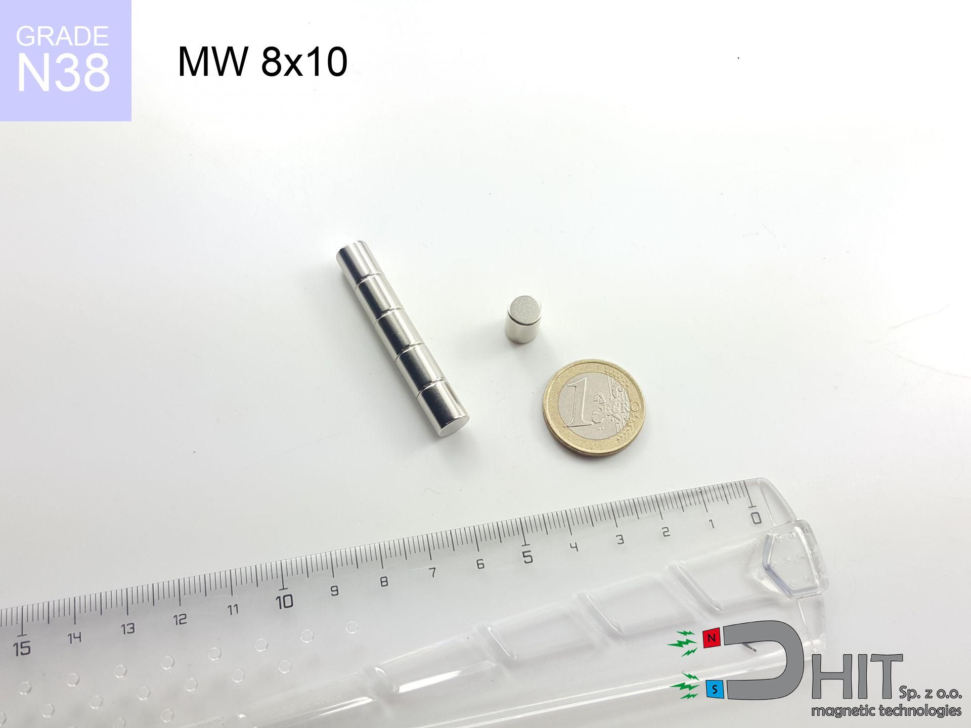
MW 8x10 / N38 - cylindrical magnet
cylindrical magnet
Catalog no 010504
GTIN/EAN: 5906301815136
- Diameter Ø
- 8 mm [±0,1 mm]
- Height
- 10 mm [±0,1 mm]
- Weight
- 3.77 g
- Magnetization Direction
- ↑ axial
- Coating
- [NiCuNi] Nickel
How we measure these parameters — certificates and measurements
1.220 zł net / pcs
1.501 zł with VAT (23% VAT) / pcs
bulk discounts:
Need more?Frequently asked questions
Where can I buy strong cylindrical neodymium magnets?
Can a small cylindrical magnet provide a strong grip for precise workshop work?
Which cylindrical magnet can work at a higher temperature?
Engineering report for this magnet
Full PDF analysis: pull and shear force, effect of distance, temperature and plate thickness, safety distances and the demagnetization curve.
Call us now
+48 888 99 98 98
alternatively let us know using
contact form
the contact section.
Specifications and structure of a neodymium magnet can be estimated using our
power calculator.
Order by 14:00 and we’ll ship today!
Technical of the product - MW 8x10 / N38 - cylindrical magnet
Specification / characteristics - MW 8x10 / N38 - cylindrical magnet
| properties | values |
|---|---|
| Cat. no. | 010504 |
| GTIN/EAN | 5906301815136 |
| Production/Distribution | Dhit sp. z o.o. |
| Country of origin | Poland / China / Germany |
| Customs code | 85059029 |
| Diameter Ø | 8 mm [±0,1 mm] |
| Height | 10 mm [±0,1 mm] |
| Weight | 3.77 g |
| Magnetization Direction | ↑ axial |
| Load capacity ~ ? | 1.84 kg / 18.04 N |
| Magnetic Induction ~ ? | 574.74 mT / 5747 Gs |
| Coating | [NiCuNi] Nickel |
| Manufacturing Tolerance | ±0.1 mm |
Magnetic properties of material N38
| properties | values | units |
|---|---|---|
| Remanence Br ? | 12.2-12.6 | kGs |
| Remanence Br ? | 1220-1260 | mT |
| Coercivity bHc ? | 10.8-11.5 | kOe |
| Coercivity bHc ? | 860-915 | kA/m |
| Intrinsic coercivity iHc | ≥ 12 | kOe |
| Intrinsic coercivity iHc | ≥ 955 | kA/m |
| Energy product BHmax ? | 36-38 | BH max MGOe |
| Energy product BHmax ? | 287-303 | BH max KJ/m |
| Maximum working temperature ? | ≤ 80 | °C |
Physical properties of sintered neodymium magnets Nd2Fe14B at 20°C
| properties | values | units |
|---|---|---|
| Vickers hardness | ≥550 | Hv |
| Density | ≥7.4 | g/cm3 |
| Curie Temperature TC | 310 | °C |
| Curie Temperature TF | 590 | °F |
| Specific resistance | 150 | μΩ⋅cm |
| Bending strength | 250 | MPa |
| Compressive strength | 1000~1100 | MPa |
| Thermal expansion parallel (∥) to orientation (M) | (3-4) x 10-6 | °C-1 |
| Thermal expansion perpendicular (⊥) to orientation (M) | -(1-3) x 10-6 | °C-1 |
| Young's modulus | 1.7 x 10⁴ | kg/mm² |
Engineering modeling of the assembly - technical parameters
These values represent the result of a physical calculation. Results are based on models for the class Nd2Fe14B. Operational conditions may differ from theoretical values. Use these data as a reference point for designers.
Table 1: Static pull force (force vs gap) - interaction chart
MW 8x10 / N38
| Distance (mm) | Induction (Gauss) / mT | Pull Force (kg/lbs/g/N) | Risk Status |
|---|---|---|---|
| 0 mm |
5742 Gs
574.2 mT
|
1.84 kg / 4.06 lbs
1840.0 g / 18.1 N
|
weak grip |
| 1 mm |
4323 Gs
432.3 mT
|
1.04 kg / 2.30 lbs
1043.0 g / 10.2 N
|
weak grip |
| 2 mm |
3109 Gs
310.9 mT
|
0.54 kg / 1.19 lbs
539.5 g / 5.3 N
|
weak grip |
| 3 mm |
2206 Gs
220.6 mT
|
0.27 kg / 0.60 lbs
271.6 g / 2.7 N
|
weak grip |
| 5 mm |
1149 Gs
114.9 mT
|
0.07 kg / 0.16 lbs
73.7 g / 0.7 N
|
weak grip |
| 10 mm |
323 Gs
32.3 mT
|
0.01 kg / 0.01 lbs
5.8 g / 0.1 N
|
weak grip |
| 15 mm |
131 Gs
13.1 mT
|
0.00 kg / 0.00 lbs
1.0 g / 0.0 N
|
weak grip |
| 20 mm |
66 Gs
6.6 mT
|
0.00 kg / 0.00 lbs
0.2 g / 0.0 N
|
weak grip |
| 30 mm |
24 Gs
2.4 mT
|
0.00 kg / 0.00 lbs
0.0 g / 0.0 N
|
weak grip |
| 50 mm |
6 Gs
0.6 mT
|
0.00 kg / 0.00 lbs
0.0 g / 0.0 N
|
weak grip |
Table 2: Shear capacity (wall)
MW 8x10 / N38
| Distance (mm) | Friction coefficient | Pull Force (kg/lbs/g/N) |
|---|---|---|
| 0 mm | Stal (~0.2) |
0.37 kg / 0.81 lbs
368.0 g / 3.6 N
|
| 1 mm | Stal (~0.2) |
0.21 kg / 0.46 lbs
208.0 g / 2.0 N
|
| 2 mm | Stal (~0.2) |
0.11 kg / 0.24 lbs
108.0 g / 1.1 N
|
| 3 mm | Stal (~0.2) |
0.05 kg / 0.12 lbs
54.0 g / 0.5 N
|
| 5 mm | Stal (~0.2) |
0.01 kg / 0.03 lbs
14.0 g / 0.1 N
|
| 10 mm | Stal (~0.2) |
0.00 kg / 0.00 lbs
2.0 g / 0.0 N
|
| 15 mm | Stal (~0.2) |
0.00 kg / 0.00 lbs
0.0 g / 0.0 N
|
| 20 mm | Stal (~0.2) |
0.00 kg / 0.00 lbs
0.0 g / 0.0 N
|
| 30 mm | Stal (~0.2) |
0.00 kg / 0.00 lbs
0.0 g / 0.0 N
|
| 50 mm | Stal (~0.2) |
0.00 kg / 0.00 lbs
0.0 g / 0.0 N
|
Table 3: Wall mounting (shearing) - behavior on slippery surfaces
MW 8x10 / N38
| Surface type | Friction coefficient / % Mocy | Max load (kg/lbs/g/N) |
|---|---|---|
| Raw steel |
µ = 0.3
30% Nominalnej Siły
|
0.55 kg / 1.22 lbs
552.0 g / 5.4 N
|
| Painted steel (standard) |
µ = 0.2
20% Nominalnej Siły
|
0.37 kg / 0.81 lbs
368.0 g / 3.6 N
|
| Oily/slippery steel |
µ = 0.1
10% Nominalnej Siły
|
0.18 kg / 0.41 lbs
184.0 g / 1.8 N
|
| Magnet with anti-slip rubber |
µ = 0.5
50% Nominalnej Siły
|
0.92 kg / 2.03 lbs
920.0 g / 9.0 N
|
Table 4: Material efficiency (substrate influence) - sheet metal selection
MW 8x10 / N38
| Steel thickness (mm) | % power | Real pull force (kg/lbs/g/N) |
|---|---|---|
| 0.5 mm |
|
0.18 kg / 0.41 lbs
184.0 g / 1.8 N
|
| 1 mm |
|
0.46 kg / 1.01 lbs
460.0 g / 4.5 N
|
| 2 mm |
|
0.92 kg / 2.03 lbs
920.0 g / 9.0 N
|
| 3 mm |
|
1.38 kg / 3.04 lbs
1380.0 g / 13.5 N
|
| 5 mm |
|
1.84 kg / 4.06 lbs
1840.0 g / 18.1 N
|
| 10 mm |
|
1.84 kg / 4.06 lbs
1840.0 g / 18.1 N
|
| 11 mm |
|
1.84 kg / 4.06 lbs
1840.0 g / 18.1 N
|
| 12 mm |
|
1.84 kg / 4.06 lbs
1840.0 g / 18.1 N
|
Table 5: Thermal stability (stability) - thermal limit
MW 8x10 / N38
| Ambient temp. (°C) | Power loss | Remaining pull (kg/lbs/g/N) | Status |
|---|---|---|---|
| 20 °C | 0.0% |
1.84 kg / 4.06 lbs
1840.0 g / 18.1 N
|
OK |
| 40 °C | -2.2% |
1.80 kg / 3.97 lbs
1799.5 g / 17.7 N
|
OK |
| 60 °C | -4.4% |
1.76 kg / 3.88 lbs
1759.0 g / 17.3 N
|
OK |
| 80 °C | -6.6% |
1.72 kg / 3.79 lbs
1718.6 g / 16.9 N
|
|
| 100 °C | -28.8% |
1.31 kg / 2.89 lbs
1310.1 g / 12.9 N
|
Table 6: Two magnets (attraction) - field range
MW 8x10 / N38
| Gap (mm) | Attraction (kg/lbs) (N-S) | Sliding Force (kg/lbs/g/N) | Repulsion (kg/lbs) (N-N) |
|---|---|---|---|
| 0 mm |
10.22 kg / 22.52 lbs
6 064 Gs
|
1.53 kg / 3.38 lbs
1532 g / 15.0 N
|
N/A |
| 1 mm |
7.82 kg / 17.25 lbs
10 050 Gs
|
1.17 kg / 2.59 lbs
1174 g / 11.5 N
|
7.04 kg / 15.52 lbs
~0 Gs
|
| 2 mm |
5.79 kg / 12.77 lbs
8 646 Gs
|
0.87 kg / 1.92 lbs
869 g / 8.5 N
|
5.21 kg / 11.49 lbs
~0 Gs
|
| 3 mm |
4.19 kg / 9.25 lbs
7 358 Gs
|
0.63 kg / 1.39 lbs
629 g / 6.2 N
|
3.77 kg / 8.32 lbs
~0 Gs
|
| 5 mm |
2.13 kg / 4.69 lbs
5 238 Gs
|
0.32 kg / 0.70 lbs
319 g / 3.1 N
|
1.91 kg / 4.22 lbs
~0 Gs
|
| 10 mm |
0.41 kg / 0.90 lbs
2 299 Gs
|
0.06 kg / 0.14 lbs
61 g / 0.6 N
|
0.37 kg / 0.81 lbs
~0 Gs
|
| 20 mm |
0.03 kg / 0.07 lbs
646 Gs
|
0.00 kg / 0.01 lbs
5 g / 0.0 N
|
0.03 kg / 0.06 lbs
~0 Gs
|
| 50 mm |
0.00 kg / 0.00 lbs
76 Gs
|
0.00 kg / 0.00 lbs
0 g / 0.0 N
|
0.00 kg / 0.00 lbs
~0 Gs
|
| 60 mm |
0.00 kg / 0.00 lbs
47 Gs
|
0.00 kg / 0.00 lbs
0 g / 0.0 N
|
0.00 kg / 0.00 lbs
~0 Gs
|
| 70 mm |
0.00 kg / 0.00 lbs
31 Gs
|
0.00 kg / 0.00 lbs
0 g / 0.0 N
|
0.00 kg / 0.00 lbs
~0 Gs
|
| 80 mm |
0.00 kg / 0.00 lbs
22 Gs
|
0.00 kg / 0.00 lbs
0 g / 0.0 N
|
0.00 kg / 0.00 lbs
~0 Gs
|
| 90 mm |
0.00 kg / 0.00 lbs
16 Gs
|
0.00 kg / 0.00 lbs
0 g / 0.0 N
|
0.00 kg / 0.00 lbs
~0 Gs
|
| 100 mm |
0.00 kg / 0.00 lbs
12 Gs
|
0.00 kg / 0.00 lbs
0 g / 0.0 N
|
0.00 kg / 0.00 lbs
~0 Gs
|
Table 7: Safety (HSE) (implants) - warnings
MW 8x10 / N38
| Object / Device | Limit (Gauss) / mT | Safe distance |
|---|---|---|
| Pacemaker | 5 Gs (0.5 mT) | 5.5 cm |
| Hearing aid | 10 Gs (1.0 mT) | 4.5 cm |
| Timepiece | 20 Gs (2.0 mT) | 3.5 cm |
| Phone / Smartphone | 40 Gs (4.0 mT) | 2.5 cm |
| Remote | 50 Gs (5.0 mT) | 2.5 cm |
| Payment card | 400 Gs (40.0 mT) | 1.0 cm |
| HDD hard drive | 600 Gs (60.0 mT) | 1.0 cm |
Table 8: Collisions (kinetic energy) - warning
MW 8x10 / N38
| Start from (mm) | Speed (km/h) | Energy (J) | Predicted outcome |
|---|---|---|---|
| 10 mm |
14.23 km/h
(3.95 m/s)
|
0.03 J | |
| 30 mm |
14.27 km/h
(3.96 m/s)
|
0.03 J | |
| 50 mm |
14.27 km/h
(3.96 m/s)
|
0.03 J | |
| 100 mm |
14.27 km/h
(3.96 m/s)
|
0.03 J |
Table 9: Anti-corrosion coating durability
MW 8x10 / N38
| Technical parameter | Value / Description |
|---|---|
| Coating type | [NiCuNi] Nickel |
| Layer structure | Nickel - Copper - Nickel |
| Layer thickness | 10-20 µm |
| Salt spray test (SST) ? | 24 h |
| Recommended environment | Indoors only (dry) |
Table 10: Electrical data (Flux)
MW 8x10 / N38
| Parameter | Value | SI Unit / Description |
|---|---|---|
| Magnetic Flux | 3 040 Mx | 30.4 µWb |
| Pc Coefficient | 1.00 | High (Stable) |
Table 11: Physics of underwater searching
MW 8x10 / N38
| Environment | Effective steel pull | Effect |
|---|---|---|
| Air (land) | 1.84 kg | Standard |
| Water (riverbed) |
2.11 kg
(+0.27 kg buoyancy gain)
|
+14.5% |
1. Sliding resistance
*Caution: On a vertical wall, the magnet holds just approx. 20-30% of its max power.
2. Steel saturation
*Thin metal sheet (e.g. computer case) severely limits the holding force.
3. Heat tolerance
N38: the maximum material working temperature is 80°C. Permitted conditions also depend on the shape and magnetic circuit.
4. Demagnetization curve and operating point (B-H)
chart generated for the permeance coefficient Pc (Permeance Coefficient) = 1.00
This simulation demonstrates the magnetic stability of the selected magnet under specific geometric conditions. The solid red line represents the demagnetization curve (material potential), while the dashed blue line is the load line based on the magnet's geometry. The Pc (Permeance Coefficient), also known as the load line slope, is a dimensionless value that describes the relationship between the magnet's shape and its magnetic stability. The intersection of these two lines (the black dot) is the operating point — it determines the actual magnetic flux density generated by the magnet in this specific configuration. A higher Pc value means the magnet is more 'slender' (tall relative to its area), resulting in a higher operating point and better resistance to irreversible demagnetization caused by external fields or temperature. A value of 0.42 is relatively low (typical for flat magnets), meaning the operating point is closer to the 'knee' of the curve — caution is advised when operating at temperatures near the maximum limit to avoid strength loss.
Chemical composition
| iron (Fe) | 64% – 68% |
| neodymium (Nd) | 29% – 32% |
| boron (B) | 1.1% – 1.2% |
| dysprosium (Dy) | 0.5% – 2.0% |
| coating (Ni-Cu-Ni) | < 0.05% |
Ecology and recycling (GPSR)
| recyclability (EoL) | 100% |
| recycled raw materials | ~10% (pre-cons) |
| carbon footprint | low / zredukowany |
| waste code (EWC) | 16 02 16 |
Other offers
![UMP 94x28 [3xM10] GW F300 GOLD / N38 - search holder](https://cdn3.dhit.pl/graphics/products/ump-94x28-m10-gw-f300-vux.jpg "UMP 94x28 [3xM10] GW F300 GOLD / N38 - search holder")
![HH 36x7.5 [M6] / N38 - through hole magnetic holder](https://cdn3.dhit.pl/graphics/products/hh-36x7.5-m6-bez.jpg "HH 36x7.5 [M6] / N38 - through hole magnetic holder")

Advantages as well as disadvantages of Nd2Fe14B magnets.
Strengths
- They have stable power, and over more than 10 years their attraction force decreases symbolically – ~1% (according to theory),
- Magnets very well resist against demagnetization caused by ambient magnetic noise,
- The use of an refined finish of noble metals (nickel, gold, silver) causes the element to have aesthetics,
- They are known for high magnetic induction at the operating surface, which improves attraction properties,
- Neodymium magnets are characterized by extremely high magnetic induction on the magnet surface and can function (depending on the shape) even at a temperature of 230°C or more...
- Thanks to flexibility in forming and the ability to adapt to unusual requirements,
- Fundamental importance in modern industrial fields – they find application in data components, electric drive systems, medical devices, and industrial machines.
- Thanks to their power density, small magnets offer high operating force, occupying minimum space,
Limitations
- To avoid cracks under impact, we recommend using special steel holders. Such a solution protects the magnet and simultaneously improves its durability.
- Do not exceed this material temperature limit: 80°C. Overheating may permanently weaken the magnet.
- Due to the susceptibility of magnets to corrosion in a humid environment, we advise using waterproof magnets made of rubber, plastic or other material resistant to moisture, when using outdoors
- We suggest casing - magnetic holder, due to difficulties in realizing nuts inside the magnet and complex forms.
- Potential hazard related to microscopic parts of magnets pose a threat, in case of ingestion, which is particularly important in the aspect of protecting the youngest. Furthermore, small elements of these products can be problematic in diagnostics medical after entering the body.
- Higher cost of purchase is a significant factor to consider compared to ceramic magnets, especially in budget applications
Lifting parameters
Highest magnetic holding force – what it depends on?
- using a plate made of low-carbon steel, serving as a ideal flux conductor
- possessing a thickness of min. 10 mm to avoid saturation
- with an ideally smooth touching surface
- without the slightest insulating layer between the magnet and steel
- for force acting at a right angle (pull-off, not shear)
- at conditions approx. 20°C
Practical lifting capacity: influencing factors
- Clearance – the presence of foreign body (rust, dirt, gap) acts as an insulator, which reduces capacity steeply (even by 50% at 0.5 mm).
- Pull-off angle – note that the magnet holds strongest perpendicularly. Under sliding down, the holding force drops significantly, often to levels of 20-30% of the nominal value.
- Element thickness – for full efficiency, the steel must be adequately massive. Thin sheet limits the attraction force (the magnet "punches through" it).
- Material type – the best choice is high-permeability steel. Cast iron may attract less.
- Base smoothness – the more even the surface, the larger the contact zone and stronger the hold. Roughness acts like micro-gaps.
- Temperature – temperature increase causes a temporary drop of induction. It is worth remembering the thermal limit for a given model.
Lifting capacity testing was conducted on plates with a smooth surface of suitable thickness, under a perpendicular pulling force, in contrast under shearing force the lifting capacity is smaller. In addition, even a small distance between the magnet’s surface and the plate decreases the lifting capacity.
Warnings
Danger to pacemakers
Warning for patients: Strong magnetic fields disrupt electronics. Keep minimum 30 cm distance or request help to handle the magnets.
Adults only
NdFeB magnets are not toys. Accidental ingestion of multiple magnets can lead to them connecting inside the digestive tract, which poses a severe health hazard and requires urgent medical intervention.
Cards and drives
Data protection: Neodymium magnets can damage data carriers and sensitive devices (pacemakers, medical aids, mechanical watches).
Dust is flammable
Drilling and cutting of NdFeB material poses a fire hazard. Magnetic powder reacts violently with oxygen and is hard to extinguish.
Allergy Warning
Allergy Notice: The Ni-Cu-Ni coating consists of nickel. If redness appears, immediately stop working with magnets and wear gloves.
Keep away from electronics
Remember: rare earth magnets produce a field that interferes with precision electronics. Maintain a separation from your phone, tablet, and navigation systems.
Immense force
Before use, check safety instructions. Uncontrolled attraction can destroy the magnet or injure your hand. Think ahead.
Fragile material
NdFeB magnets are sintered ceramics, meaning they are prone to chipping. Clashing of two magnets leads to them shattering into small pieces.
Heat sensitivity
Standard neodymium magnets (N-type) undergo demagnetization when the temperature goes above 80°C. Damage is permanent.
Bodily injuries
Big blocks can break fingers in a fraction of a second. Do not place your hand betwixt two attracting surfaces.
Tabela kosztu i czasu dostawy
Płatność przed wysyłką:

GLS kurier
Przesyłka będzie u Ciebie za 2-3 dni
14.99 ZŁ

InPost Paczkomaty 24/7
Przesyłka będzie u Ciebie za 1-2 dni
12.30 ZŁ
Płatność przy odbiorze (pobranie):
GLS kurier
Przesyłka będzie u Ciebie za 1-2 dni
23.00 ZŁ