

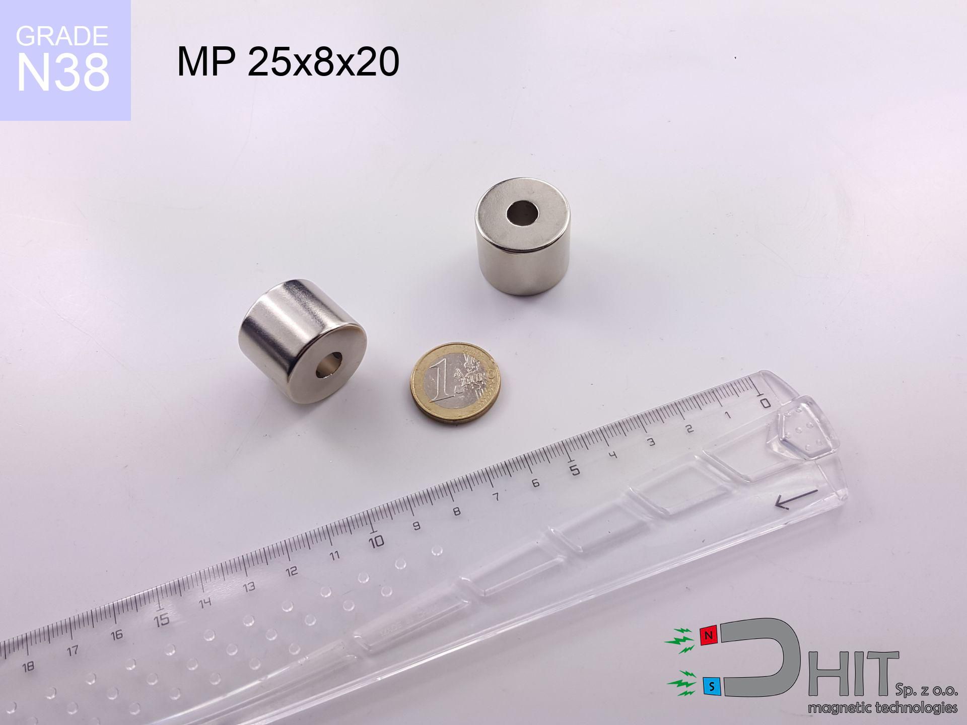
MP 25x8x20 / N38 - ring magnet
ring magnet
Catalog no 030450
GTIN/EAN: 5906301812340
- Diameter
- 25 mm [±0,1 mm]
- internal diameter Ø
- 8 mm [±0,1 mm]
- Height
- 20 mm [±0,1 mm]
- Weight
- 66.09 g
- Magnetization Direction
- ↑ axial
- Coating
- [NiCuNi] Nickel
How we measure these parameters — certificates and measurements
33.91 zł net / pcs
41.71 zł with VAT (23% VAT) / pcs
bulk discounts:
Need more?Frequently asked questions
Where can I compare prices of ring magnets for mounting in Poland?
Are ring magnets resistant to damage?
Which ring magnet is suitable for an outdoor structure?
Where can I check the available sizes of neodymium ring magnets?
Engineering report for this magnet
Full PDF analysis: pull and shear force, effect of distance, temperature and plate thickness, safety distances and the demagnetization curve.
Call us now
+48 888 99 98 98
alternatively let us know using
contact form
the contact section.
Specifications and structure of a neodymium magnet can be estimated using our
power calculator.
Order by 14:00 and we’ll ship today!
Technical - MP 25x8x20 / N38 - ring magnet
Specification / characteristics - MP 25x8x20 / N38 - ring magnet
| properties | values |
|---|---|
| Cat. no. | 030450 |
| GTIN/EAN | 5906301812340 |
| Production/Distribution | Dhit sp. z o.o. |
| Country of origin | Poland / China / Germany |
| Customs code | 85059029 |
| Diameter | 25 mm [±0,1 mm] |
| internal diameter Ø | 8 mm [±0,1 mm] |
| Height | 20 mm [±0,1 mm] |
| Weight | 66.09 g |
| Magnetization Direction | ↑ axial |
| Load capacity ~ ? | 19.02 kg / 186.54 N |
| Magnetic Induction ~ ? | 525.50 mT / 5255 Gs |
| Coating | [NiCuNi] Nickel |
| Manufacturing Tolerance | ±0.1 mm |
Magnetic properties of material N38
| properties | values | units |
|---|---|---|
| Remanence Br ? | 12.2-12.6 | kGs |
| Remanence Br ? | 1220-1260 | mT |
| Coercivity bHc ? | 10.8-11.5 | kOe |
| Coercivity bHc ? | 860-915 | kA/m |
| Intrinsic coercivity iHc | ≥ 12 | kOe |
| Intrinsic coercivity iHc | ≥ 955 | kA/m |
| Energy product BHmax ? | 36-38 | BH max MGOe |
| Energy product BHmax ? | 287-303 | BH max KJ/m |
| Maximum working temperature ? | ≤ 80 | °C |
Physical properties of sintered neodymium magnets Nd2Fe14B at 20°C
| properties | values | units |
|---|---|---|
| Vickers hardness | ≥550 | Hv |
| Density | ≥7.4 | g/cm3 |
| Curie Temperature TC | 310 | °C |
| Curie Temperature TF | 590 | °F |
| Specific resistance | 150 | μΩ⋅cm |
| Bending strength | 250 | MPa |
| Compressive strength | 1000~1100 | MPa |
| Thermal expansion parallel (∥) to orientation (M) | (3-4) x 10-6 | °C-1 |
| Thermal expansion perpendicular (⊥) to orientation (M) | -(1-3) x 10-6 | °C-1 |
| Young's modulus | 1.7 x 10⁴ | kg/mm² |
Physical modeling of the magnet - data
Presented data are the result of a mathematical analysis. Values were calculated on algorithms for the material Nd2Fe14B. Real-world parameters may differ. Use these calculations as a supplementary guide during assembly planning.
Table 1: Static force (pull vs distance) - characteristics
MP 25x8x20 / N38
| Distance (mm) | Induction (Gauss) / mT | Pull Force (kg/lbs/g/N) | Risk Status |
|---|---|---|---|
| 0 mm |
5777 Gs
577.7 mT
|
19.02 kg / 41.93 lbs
19020.0 g / 186.6 N
|
dangerous! |
| 1 mm |
5310 Gs
531.0 mT
|
16.07 kg / 35.42 lbs
16067.7 g / 157.6 N
|
dangerous! |
| 2 mm |
4846 Gs
484.6 mT
|
13.38 kg / 29.50 lbs
13380.1 g / 131.3 N
|
dangerous! |
| 3 mm |
4397 Gs
439.7 mT
|
11.02 kg / 24.29 lbs
11019.3 g / 108.1 N
|
dangerous! |
| 5 mm |
3576 Gs
357.6 mT
|
7.29 kg / 16.07 lbs
7287.1 g / 71.5 N
|
strong |
| 10 mm |
2073 Gs
207.3 mT
|
2.45 kg / 5.40 lbs
2448.1 g / 24.0 N
|
strong |
| 15 mm |
1231 Gs
123.1 mT
|
0.86 kg / 1.90 lbs
863.8 g / 8.5 N
|
low risk |
| 20 mm |
773 Gs
77.3 mT
|
0.34 kg / 0.75 lbs
340.1 g / 3.3 N
|
low risk |
| 30 mm |
356 Gs
35.6 mT
|
0.07 kg / 0.16 lbs
72.1 g / 0.7 N
|
low risk |
| 50 mm |
115 Gs
11.5 mT
|
0.01 kg / 0.02 lbs
7.5 g / 0.1 N
|
low risk |
Table 2: Sliding hold (wall)
MP 25x8x20 / N38
| Distance (mm) | Friction coefficient | Pull Force (kg/lbs/g/N) |
|---|---|---|
| 0 mm | Stal (~0.2) |
3.80 kg / 8.39 lbs
3804.0 g / 37.3 N
|
| 1 mm | Stal (~0.2) |
3.21 kg / 7.09 lbs
3214.0 g / 31.5 N
|
| 2 mm | Stal (~0.2) |
2.68 kg / 5.90 lbs
2676.0 g / 26.3 N
|
| 3 mm | Stal (~0.2) |
2.20 kg / 4.86 lbs
2204.0 g / 21.6 N
|
| 5 mm | Stal (~0.2) |
1.46 kg / 3.21 lbs
1458.0 g / 14.3 N
|
| 10 mm | Stal (~0.2) |
0.49 kg / 1.08 lbs
490.0 g / 4.8 N
|
| 15 mm | Stal (~0.2) |
0.17 kg / 0.38 lbs
172.0 g / 1.7 N
|
| 20 mm | Stal (~0.2) |
0.07 kg / 0.15 lbs
68.0 g / 0.7 N
|
| 30 mm | Stal (~0.2) |
0.01 kg / 0.03 lbs
14.0 g / 0.1 N
|
| 50 mm | Stal (~0.2) |
0.00 kg / 0.00 lbs
2.0 g / 0.0 N
|
Table 3: Vertical assembly (shearing) - behavior on slippery surfaces
MP 25x8x20 / N38
| Surface type | Friction coefficient / % Mocy | Max load (kg/lbs/g/N) |
|---|---|---|
| Raw steel |
µ = 0.3
30% Nominalnej Siły
|
5.71 kg / 12.58 lbs
5706.0 g / 56.0 N
|
| Painted steel (standard) |
µ = 0.2
20% Nominalnej Siły
|
3.80 kg / 8.39 lbs
3804.0 g / 37.3 N
|
| Oily/slippery steel |
µ = 0.1
10% Nominalnej Siły
|
1.90 kg / 4.19 lbs
1902.0 g / 18.7 N
|
| Magnet with anti-slip rubber |
µ = 0.5
50% Nominalnej Siły
|
9.51 kg / 20.97 lbs
9510.0 g / 93.3 N
|
Table 4: Steel thickness (saturation) - sheet metal selection
MP 25x8x20 / N38
| Steel thickness (mm) | % power | Real pull force (kg/lbs/g/N) |
|---|---|---|
| 0.5 mm |
|
0.95 kg / 2.10 lbs
951.0 g / 9.3 N
|
| 1 mm |
|
2.38 kg / 5.24 lbs
2377.5 g / 23.3 N
|
| 2 mm |
|
4.76 kg / 10.48 lbs
4755.0 g / 46.6 N
|
| 3 mm |
|
7.13 kg / 15.72 lbs
7132.5 g / 70.0 N
|
| 5 mm |
|
11.89 kg / 26.21 lbs
11887.5 g / 116.6 N
|
| 10 mm |
|
19.02 kg / 41.93 lbs
19020.0 g / 186.6 N
|
| 11 mm |
|
19.02 kg / 41.93 lbs
19020.0 g / 186.6 N
|
| 12 mm |
|
19.02 kg / 41.93 lbs
19020.0 g / 186.6 N
|
Table 5: Working in heat (stability) - power drop
MP 25x8x20 / N38
| Ambient temp. (°C) | Power loss | Remaining pull (kg/lbs/g/N) | Status |
|---|---|---|---|
| 20 °C | 0.0% |
19.02 kg / 41.93 lbs
19020.0 g / 186.6 N
|
OK |
| 40 °C | -2.2% |
18.60 kg / 41.01 lbs
18601.6 g / 182.5 N
|
OK |
| 60 °C | -4.4% |
18.18 kg / 40.09 lbs
18183.1 g / 178.4 N
|
OK |
| 80 °C | -6.6% |
17.76 kg / 39.16 lbs
17764.7 g / 174.3 N
|
|
| 100 °C | -28.8% |
13.54 kg / 29.86 lbs
13542.2 g / 132.8 N
|
Table 6: Two magnets (attraction) - field range
MP 25x8x20 / N38
| Gap (mm) | Attraction (kg/lbs) (N-S) | Lateral Force (kg/lbs/g/N) | Repulsion (kg/lbs) (N-N) |
|---|---|---|---|
| 0 mm |
30.91 kg / 68.14 lbs
6 082 Gs
|
4.64 kg / 10.22 lbs
4636 g / 45.5 N
|
N/A |
| 1 mm |
28.48 kg / 62.79 lbs
11 091 Gs
|
4.27 kg / 9.42 lbs
4272 g / 41.9 N
|
25.63 kg / 56.51 lbs
~0 Gs
|
| 2 mm |
26.11 kg / 57.57 lbs
10 620 Gs
|
3.92 kg / 8.63 lbs
3917 g / 38.4 N
|
23.50 kg / 51.81 lbs
~0 Gs
|
| 3 mm |
23.86 kg / 52.61 lbs
10 153 Gs
|
3.58 kg / 7.89 lbs
3580 g / 35.1 N
|
21.48 kg / 47.35 lbs
~0 Gs
|
| 5 mm |
19.76 kg / 43.56 lbs
9 238 Gs
|
2.96 kg / 6.53 lbs
2964 g / 29.1 N
|
17.78 kg / 39.20 lbs
~0 Gs
|
| 10 mm |
11.84 kg / 26.11 lbs
7 152 Gs
|
1.78 kg / 3.92 lbs
1776 g / 17.4 N
|
10.66 kg / 23.50 lbs
~0 Gs
|
| 20 mm |
3.98 kg / 8.77 lbs
4 145 Gs
|
0.60 kg / 1.32 lbs
597 g / 5.9 N
|
3.58 kg / 7.89 lbs
~0 Gs
|
| 50 mm |
0.24 kg / 0.54 lbs
1 024 Gs
|
0.04 kg / 0.08 lbs
36 g / 0.4 N
|
0.22 kg / 0.48 lbs
~0 Gs
|
| 60 mm |
0.12 kg / 0.26 lbs
712 Gs
|
0.02 kg / 0.04 lbs
18 g / 0.2 N
|
0.11 kg / 0.23 lbs
~0 Gs
|
| 70 mm |
0.06 kg / 0.13 lbs
514 Gs
|
0.01 kg / 0.02 lbs
9 g / 0.1 N
|
0.06 kg / 0.12 lbs
~0 Gs
|
| 80 mm |
0.03 kg / 0.07 lbs
383 Gs
|
0.01 kg / 0.01 lbs
5 g / 0.1 N
|
0.03 kg / 0.07 lbs
~0 Gs
|
| 90 mm |
0.02 kg / 0.04 lbs
293 Gs
|
0.00 kg / 0.01 lbs
3 g / 0.0 N
|
0.02 kg / 0.04 lbs
~0 Gs
|
| 100 mm |
0.01 kg / 0.03 lbs
230 Gs
|
0.00 kg / 0.00 lbs
2 g / 0.0 N
|
0.01 kg / 0.02 lbs
~0 Gs
|
Table 7: Safety (HSE) (implants) - warnings
MP 25x8x20 / N38
| Object / Device | Limit (Gauss) / mT | Safe distance |
|---|---|---|
| Pacemaker | 5 Gs (0.5 mT) | 17.0 cm |
| Hearing aid | 10 Gs (1.0 mT) | 13.5 cm |
| Timepiece | 20 Gs (2.0 mT) | 10.5 cm |
| Mobile device | 40 Gs (4.0 mT) | 8.0 cm |
| Remote | 50 Gs (5.0 mT) | 7.5 cm |
| Payment card | 400 Gs (40.0 mT) | 3.0 cm |
| HDD hard drive | 600 Gs (60.0 mT) | 2.5 cm |
Table 8: Dynamics (cracking risk) - warning
MP 25x8x20 / N38
| Start from (mm) | Speed (km/h) | Energy (J) | Predicted outcome |
|---|---|---|---|
| 10 mm |
18.05 km/h
(5.01 m/s)
|
0.83 J | |
| 30 mm |
19.29 km/h
(5.36 m/s)
|
0.95 J | |
| 50 mm |
19.34 km/h
(5.37 m/s)
|
0.95 J | |
| 100 mm |
19.35 km/h
(5.38 m/s)
|
0.95 J |
Table 9: Anti-corrosion coating durability
MP 25x8x20 / N38
| Technical parameter | Value / Description |
|---|---|
| Coating type | [NiCuNi] Nickel |
| Layer structure | Nickel - Copper - Nickel |
| Layer thickness | 10-20 µm |
| Salt spray test (SST) ? | 24 h |
| Recommended environment | Indoors only (dry) |
Table 10: Electrical data (Flux)
MP 25x8x20 / N38
| Parameter | Value | SI Unit / Description |
|---|---|---|
| Magnetic Flux | 10 108 Mx | 101.1 µWb |
| Pc Coefficient | 1.25 | High (Stable) |
Table 11: Physics of underwater searching
MP 25x8x20 / N38
| Environment | Effective steel pull | Effect |
|---|---|---|
| Air (land) | 19.02 kg | Standard |
| Water (riverbed) |
21.78 kg
(+2.76 kg buoyancy gain)
|
+14.5% |
1. Shear force
*Note: On a vertical surface, the magnet holds just a fraction of its nominal pull.
2. Steel saturation
*Thin metal sheet (e.g. computer case) significantly reduces the holding force.
3. Temperature resistance
N38: the maximum material working temperature is 80°C. Permitted conditions also depend on the shape and magnetic circuit.
4. Demagnetization curve and operating point (B-H)
chart generated for the permeance coefficient Pc (Permeance Coefficient) = 1.25
The chart above illustrates the magnetic characteristics of the material within the second quadrant of the hysteresis loop. The solid red line represents the demagnetization curve (material potential), while the dashed blue line is the load line based on the magnet's geometry. The Pc (Permeance Coefficient), also known as the load line slope, is a dimensionless value that describes the relationship between the magnet's shape and its magnetic stability. The intersection of these two lines (the black dot) is the operating point — it determines the actual magnetic flux density generated by the magnet in this specific configuration. A higher Pc value means the magnet is more 'slender' (tall relative to its area), resulting in a higher operating point and better resistance to irreversible demagnetization caused by external fields or temperature. A value of 0.42 is relatively low (typical for flat magnets), meaning the operating point is closer to the 'knee' of the curve — caution is advised when operating at temperatures near the maximum limit to avoid strength loss.
Material specification
| iron (Fe) | 64% – 68% |
| neodymium (Nd) | 29% – 32% |
| boron (B) | 1.1% – 1.2% |
| dysprosium (Dy) | 0.5% – 2.0% |
| coating (Ni-Cu-Ni) | < 0.05% |
Ecology and recycling (GPSR)
| recyclability (EoL) | 100% |
| recycled raw materials | ~10% (pre-cons) |
| carbon footprint | low / zredukowany |
| waste code (EWC) | 16 02 16 |
Other products

![SM 25x275 [2xM8] / N52 - magnetic separator](https://cdn3.dhit.pl/graphics/products/sm-25x275-2xm8-vih.jpg "SM 25x275 [2xM8] / N52 - magnetic separator")
![UMH 60x15x69 [M8] / N38 - magnetic holder with hook](https://cdn3.dhit.pl/graphics/products/umh-60x15x69-m8-nij.jpg "UMH 60x15x69 [M8] / N38 - magnetic holder with hook")
Pros as well as cons of Nd2Fe14B magnets.
Advantages
- They retain attractive force for almost ten years – the drop is just ~1% (in theory),
- Neodymium magnets prove to be extremely resistant to loss of magnetic properties caused by external magnetic fields,
- The use of an elegant coating of noble metals (nickel, gold, silver) causes the element to look better,
- Magnetic induction on the top side of the magnet is impressive,
- Thanks to resistance to high temperature, they can operate (depending on the form) even at temperatures up to 230°C and higher...
- Possibility of exact modeling and adapting to atypical conditions,
- Versatile presence in innovative solutions – they are used in magnetic memories, motor assemblies, precision medical tools, also complex engineering applications.
- Thanks to concentrated force, small magnets offer high operating force, with minimal size,
Disadvantages
- At very strong impacts they can break, therefore we advise placing them in steel cases. A metal housing provides additional protection against damage and increases the magnet's durability.
- Do not exceed this material temperature limit: 80°C. Overheating may permanently weaken the magnet.
- Magnets exposed to a humid environment can rust. Therefore when using outdoors, we recommend using water-impermeable magnets made of rubber, plastic or other material resistant to moisture
- Limited ability of making threads in the magnet and complicated shapes - preferred is casing - mounting mechanism.
- Potential hazard related to microscopic parts of magnets can be dangerous, if swallowed, which becomes key in the aspect of protecting the youngest. It is also worth noting that tiny parts of these magnets can disrupt the diagnostic process medical in case of swallowing.
- High unit price – neodymium magnets cost more than other types of magnets (e.g. ferrite), which increases costs of application in large quantities
Holding force characteristics
Highest magnetic holding force – what contributes to it?
- on a plate made of structural steel, perfectly concentrating the magnetic flux
- possessing a thickness of min. 10 mm to avoid saturation
- with an ideally smooth contact surface
- with direct contact (without impurities)
- under perpendicular force vector (90-degree angle)
- at ambient temperature approx. 20 degrees Celsius
Lifting capacity in real conditions – factors
- Air gap (between the magnet and the metal), because even a tiny clearance (e.g. 0.5 mm) leads to a drastic drop in lifting capacity by up to 50% (this also applies to paint, corrosion or debris).
- Angle of force application – maximum parameter is available only during pulling at a 90° angle. The force required to slide of the magnet along the plate is usually many times smaller (approx. 1/5 of the lifting capacity).
- Plate thickness – too thin plate does not accept the full field, causing part of the flux to be wasted into the air.
- Steel type – mild steel attracts best. Alloy admixtures reduce magnetic permeability and lifting capacity.
- Surface quality – the more even the plate, the better the adhesion and stronger the hold. Unevenness acts like micro-gaps.
- Heat – NdFeB sinters have a negative temperature coefficient. At higher temperatures they are weaker, and at low temperatures they can be stronger (up to a certain limit).
Lifting capacity was determined using a smooth steel plate of optimal thickness (min. 20 mm), under perpendicular detachment force, whereas under parallel forces the holding force is lower. In addition, even a minimal clearance between the magnet’s surface and the plate lowers the holding force.
Precautions when working with NdFeB magnets
Warning for allergy sufferers
Medical facts indicate that nickel (standard magnet coating) is a common allergen. For allergy sufferers, refrain from touching magnets with bare hands and choose encased magnets.
Hand protection
Pinching hazard: The attraction force is so immense that it can result in blood blisters, crushing, and broken bones. Use thick gloves.
Impact on smartphones
Note: neodymium magnets generate a field that interferes with sensitive sensors. Maintain a separation from your mobile, tablet, and navigation systems.
Risk of cracking
Protect your eyes. Magnets can fracture upon uncontrolled impact, launching sharp fragments into the air. Wear goggles.
Demagnetization risk
Standard neodymium magnets (grade N) lose power when the temperature exceeds 80°C. Damage is permanent.
Do not give to children
NdFeB magnets are not toys. Swallowing multiple magnets may result in them attracting across intestines, which poses a severe health hazard and requires immediate surgery.
Data carriers
Data protection: Strong magnets can damage payment cards and delicate electronics (pacemakers, medical aids, timepieces).
Conscious usage
Exercise caution. Rare earth magnets attract from a distance and connect with massive power, often quicker than you can react.
Danger to pacemakers
Health Alert: Neodymium magnets can deactivate heart devices and defibrillators. Stay away if you have electronic implants.
Do not drill into magnets
Drilling and cutting of neodymium magnets carries a risk of fire risk. Neodymium dust oxidizes rapidly with oxygen and is difficult to extinguish.
Tabela kosztu i czasu dostawy
Płatność przed wysyłką:

GLS kurier
Przesyłka będzie u Ciebie za 2-3 dni
14.99 ZŁ

InPost Paczkomaty 24/7
Przesyłka będzie u Ciebie za 1-2 dni
12.30 ZŁ
Płatność przy odbiorze (pobranie):
GLS kurier
Przesyłka będzie u Ciebie za 1-2 dni
23.00 ZŁ