

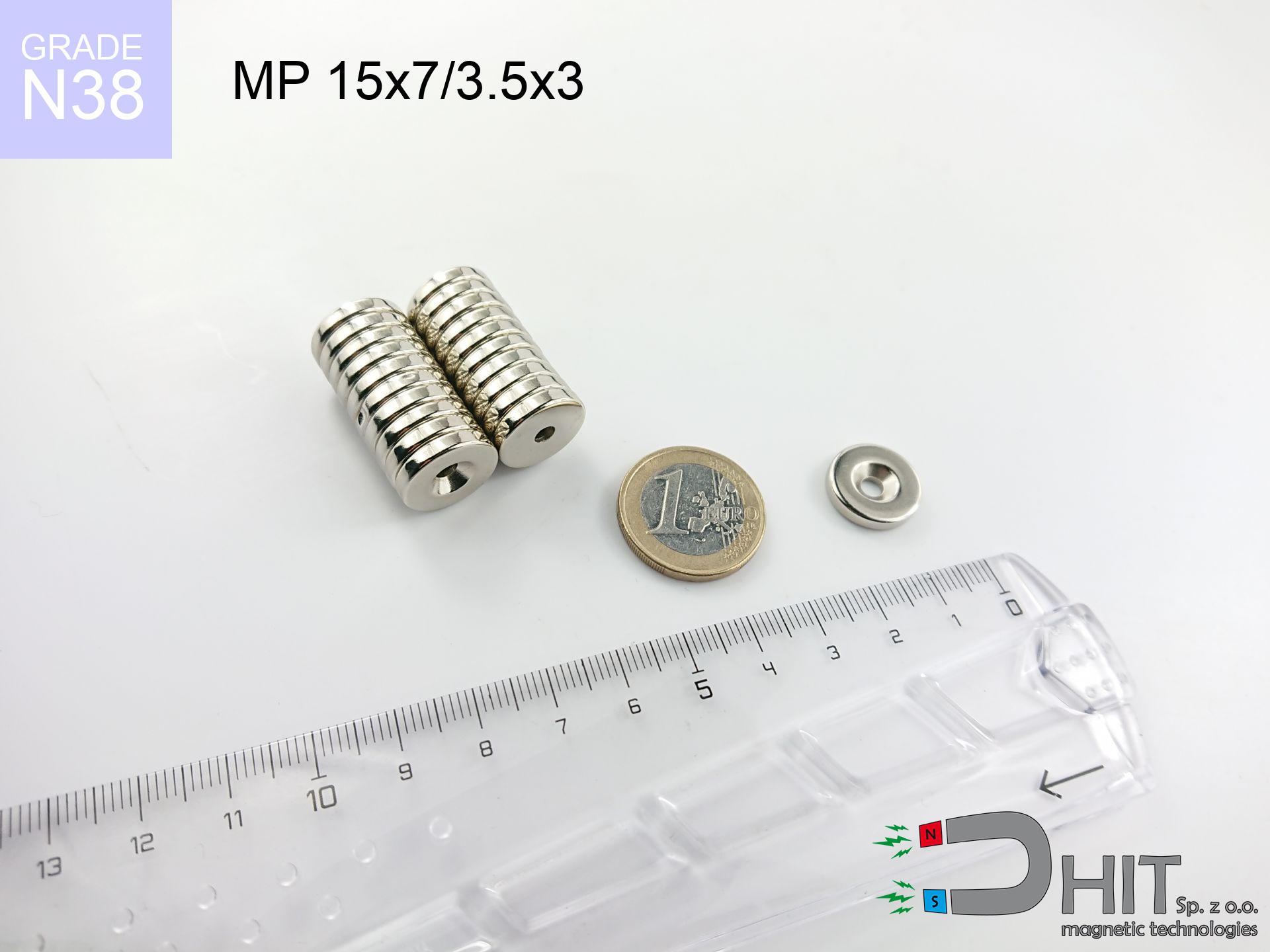
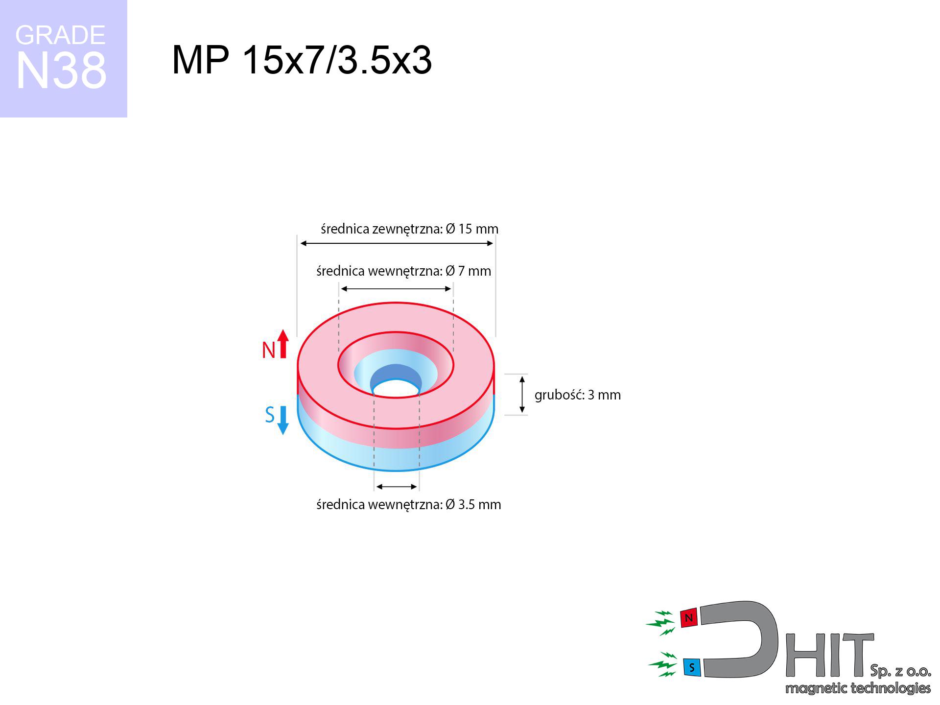
MP 15x7/3.5x3 / N38 - ring magnet
ring magnet
Catalog no 030182
GTIN/EAN: 5906301811992
- Diameter
- 15 mm [±0,1 mm]
- internal diameter Ø
- 7/3.5 mm [±0,1 mm]
- Height
- 3 mm [±0,1 mm]
- Weight
- 3.76 g
- Magnetization Direction
- ↑ axial
- Coating
- [NiCuNi] Nickel
How we measure these parameters — certificates and measurements
1.420 zł net / pcs
1.747 zł with VAT (23% VAT) / pcs
bulk discounts:
Need more?Frequently asked questions
Where can I compare prices of ring magnets for mounting in Poland?
Are ring magnets resistant to damage?
Which ring magnet is suitable for an outdoor structure?
Where can I check the available sizes of neodymium ring magnets?
Engineering report for this magnet
Full PDF analysis: pull and shear force, effect of distance, temperature and plate thickness, safety distances and the demagnetization curve.
Call us now
+48 888 99 98 98
alternatively let us know using
contact form
the contact section.
Specifications and structure of a neodymium magnet can be estimated using our
power calculator.
Order by 14:00 and we’ll ship today!
Technical details - MP 15x7/3.5x3 / N38 - ring magnet
Specification / characteristics - MP 15x7/3.5x3 / N38 - ring magnet
| properties | values |
|---|---|
| Cat. no. | 030182 |
| GTIN/EAN | 5906301811992 |
| Production/Distribution | Dhit sp. z o.o. |
| Country of origin | Poland / China / Germany |
| Customs code | 85059029 |
| Diameter | 15 mm [±0,1 mm] |
| internal diameter Ø | 7/3.5 mm [±0,1 mm] |
| Height | 3 mm [±0,1 mm] |
| Weight | 3.76 g |
| Magnetization Direction | ↑ axial |
| Load capacity ~ ? | 2.71 kg / 26.61 N |
| Magnetic Induction ~ ? | 230.16 mT / 2302 Gs |
| Coating | [NiCuNi] Nickel |
| Manufacturing Tolerance | ±0.1 mm |
Magnetic properties of material N38
| properties | values | units |
|---|---|---|
| Remanence Br ? | 12.2-12.6 | kGs |
| Remanence Br ? | 1220-1260 | mT |
| Coercivity bHc ? | 10.8-11.5 | kOe |
| Coercivity bHc ? | 860-915 | kA/m |
| Intrinsic coercivity iHc | ≥ 12 | kOe |
| Intrinsic coercivity iHc | ≥ 955 | kA/m |
| Energy product BHmax ? | 36-38 | BH max MGOe |
| Energy product BHmax ? | 287-303 | BH max KJ/m |
| Maximum working temperature ? | ≤ 80 | °C |
Physical properties of sintered neodymium magnets Nd2Fe14B at 20°C
| properties | values | units |
|---|---|---|
| Vickers hardness | ≥550 | Hv |
| Density | ≥7.4 | g/cm3 |
| Curie Temperature TC | 310 | °C |
| Curie Temperature TF | 590 | °F |
| Specific resistance | 150 | μΩ⋅cm |
| Bending strength | 250 | MPa |
| Compressive strength | 1000~1100 | MPa |
| Thermal expansion parallel (∥) to orientation (M) | (3-4) x 10-6 | °C-1 |
| Thermal expansion perpendicular (⊥) to orientation (M) | -(1-3) x 10-6 | °C-1 |
| Young's modulus | 1.7 x 10⁴ | kg/mm² |
Technical simulation of the product - technical parameters
The following information are the direct effect of a physical simulation. Values were calculated on algorithms for the material Nd2Fe14B. Real-world parameters might slightly differ from theoretical values. Treat these calculations as a reference point when designing systems.
Table 1: Static force (force vs gap) - power drop
MP 15x7/3.5x3 / N38
| Distance (mm) | Induction (Gauss) / mT | Pull Force (kg/lbs/g/N) | Risk Status |
|---|---|---|---|
| 0 mm |
1995 Gs
199.5 mT
|
2.71 kg / 5.97 pounds
2710.0 g / 26.6 N
|
medium risk |
| 1 mm |
1833 Gs
183.3 mT
|
2.29 kg / 5.05 pounds
2289.1 g / 22.5 N
|
medium risk |
| 2 mm |
1618 Gs
161.8 mT
|
1.78 kg / 3.93 pounds
1784.1 g / 17.5 N
|
safe |
| 3 mm |
1385 Gs
138.5 mT
|
1.31 kg / 2.88 pounds
1307.5 g / 12.8 N
|
safe |
| 5 mm |
959 Gs
95.9 mT
|
0.63 kg / 1.38 pounds
627.1 g / 6.2 N
|
safe |
| 10 mm |
362 Gs
36.2 mT
|
0.09 kg / 0.20 pounds
89.3 g / 0.9 N
|
safe |
| 15 mm |
156 Gs
15.6 mT
|
0.02 kg / 0.04 pounds
16.5 g / 0.2 N
|
safe |
| 20 mm |
78 Gs
7.8 mT
|
0.00 kg / 0.01 pounds
4.1 g / 0.0 N
|
safe |
| 30 mm |
27 Gs
2.7 mT
|
0.00 kg / 0.00 pounds
0.5 g / 0.0 N
|
safe |
| 50 mm |
6 Gs
0.6 mT
|
0.00 kg / 0.00 pounds
0.0 g / 0.0 N
|
safe |
Table 2: Vertical load (vertical surface)
MP 15x7/3.5x3 / N38
| Distance (mm) | Friction coefficient | Pull Force (kg/lbs/g/N) |
|---|---|---|
| 0 mm | Stal (~0.2) |
0.54 kg / 1.19 pounds
542.0 g / 5.3 N
|
| 1 mm | Stal (~0.2) |
0.46 kg / 1.01 pounds
458.0 g / 4.5 N
|
| 2 mm | Stal (~0.2) |
0.36 kg / 0.78 pounds
356.0 g / 3.5 N
|
| 3 mm | Stal (~0.2) |
0.26 kg / 0.58 pounds
262.0 g / 2.6 N
|
| 5 mm | Stal (~0.2) |
0.13 kg / 0.28 pounds
126.0 g / 1.2 N
|
| 10 mm | Stal (~0.2) |
0.02 kg / 0.04 pounds
18.0 g / 0.2 N
|
| 15 mm | Stal (~0.2) |
0.00 kg / 0.01 pounds
4.0 g / 0.0 N
|
| 20 mm | Stal (~0.2) |
0.00 kg / 0.00 pounds
0.0 g / 0.0 N
|
| 30 mm | Stal (~0.2) |
0.00 kg / 0.00 pounds
0.0 g / 0.0 N
|
| 50 mm | Stal (~0.2) |
0.00 kg / 0.00 pounds
0.0 g / 0.0 N
|
Table 3: Vertical assembly (sliding) - vertical pull
MP 15x7/3.5x3 / N38
| Surface type | Friction coefficient / % Mocy | Max load (kg/lbs/g/N) |
|---|---|---|
| Raw steel |
µ = 0.3
30% Nominalnej Siły
|
0.81 kg / 1.79 pounds
813.0 g / 8.0 N
|
| Painted steel (standard) |
µ = 0.2
20% Nominalnej Siły
|
0.54 kg / 1.19 pounds
542.0 g / 5.3 N
|
| Oily/slippery steel |
µ = 0.1
10% Nominalnej Siły
|
0.27 kg / 0.60 pounds
271.0 g / 2.7 N
|
| Magnet with anti-slip rubber |
µ = 0.5
50% Nominalnej Siły
|
1.36 kg / 2.99 pounds
1355.0 g / 13.3 N
|
Table 4: Material efficiency (saturation) - sheet metal selection
MP 15x7/3.5x3 / N38
| Steel thickness (mm) | % power | Real pull force (kg/lbs/g/N) |
|---|---|---|
| 0.5 mm |
|
0.27 kg / 0.60 pounds
271.0 g / 2.7 N
|
| 1 mm |
|
0.68 kg / 1.49 pounds
677.5 g / 6.6 N
|
| 2 mm |
|
1.36 kg / 2.99 pounds
1355.0 g / 13.3 N
|
| 3 mm |
|
2.03 kg / 4.48 pounds
2032.5 g / 19.9 N
|
| 5 mm |
|
2.71 kg / 5.97 pounds
2710.0 g / 26.6 N
|
| 10 mm |
|
2.71 kg / 5.97 pounds
2710.0 g / 26.6 N
|
| 11 mm |
|
2.71 kg / 5.97 pounds
2710.0 g / 26.6 N
|
| 12 mm |
|
2.71 kg / 5.97 pounds
2710.0 g / 26.6 N
|
Table 5: Thermal resistance (material behavior) - resistance threshold
MP 15x7/3.5x3 / N38
| Ambient temp. (°C) | Power loss | Remaining pull (kg/lbs/g/N) | Status |
|---|---|---|---|
| 20 °C | 0.0% |
2.71 kg / 5.97 pounds
2710.0 g / 26.6 N
|
OK |
| 40 °C | -2.2% |
2.65 kg / 5.84 pounds
2650.4 g / 26.0 N
|
OK |
| 60 °C | -4.4% |
2.59 kg / 5.71 pounds
2590.8 g / 25.4 N
|
|
| 80 °C | -6.6% |
2.53 kg / 5.58 pounds
2531.1 g / 24.8 N
|
|
| 100 °C | -28.8% |
1.93 kg / 4.25 pounds
1929.5 g / 18.9 N
|
Table 6: Two magnets (repulsion) - field range
MP 15x7/3.5x3 / N38
| Gap (mm) | Attraction (kg/lbs) (N-S) | Shear Strength (kg/lbs/g/N) | Repulsion (kg/lbs) (N-N) |
|---|---|---|---|
| 0 mm |
3.48 kg / 7.68 pounds
3 483 Gs
|
0.52 kg / 1.15 pounds
523 g / 5.1 N
|
N/A |
| 1 mm |
3.24 kg / 7.14 pounds
3 846 Gs
|
0.49 kg / 1.07 pounds
486 g / 4.8 N
|
2.91 kg / 6.43 pounds
~0 Gs
|
| 2 mm |
2.94 kg / 6.49 pounds
3 666 Gs
|
0.44 kg / 0.97 pounds
441 g / 4.3 N
|
2.65 kg / 5.84 pounds
~0 Gs
|
| 3 mm |
2.62 kg / 5.78 pounds
3 460 Gs
|
0.39 kg / 0.87 pounds
393 g / 3.9 N
|
2.36 kg / 5.20 pounds
~0 Gs
|
| 5 mm |
1.98 kg / 4.36 pounds
3 004 Gs
|
0.30 kg / 0.65 pounds
296 g / 2.9 N
|
1.78 kg / 3.92 pounds
~0 Gs
|
| 10 mm |
0.81 kg / 1.78 pounds
1 919 Gs
|
0.12 kg / 0.27 pounds
121 g / 1.2 N
|
0.73 kg / 1.60 pounds
~0 Gs
|
| 20 mm |
0.11 kg / 0.25 pounds
724 Gs
|
0.02 kg / 0.04 pounds
17 g / 0.2 N
|
0.10 kg / 0.23 pounds
~0 Gs
|
| 50 mm |
0.00 kg / 0.00 pounds
88 Gs
|
0.00 kg / 0.00 pounds
0 g / 0.0 N
|
0.00 kg / 0.00 pounds
~0 Gs
|
| 60 mm |
0.00 kg / 0.00 pounds
54 Gs
|
0.00 kg / 0.00 pounds
0 g / 0.0 N
|
0.00 kg / 0.00 pounds
~0 Gs
|
| 70 mm |
0.00 kg / 0.00 pounds
35 Gs
|
0.00 kg / 0.00 pounds
0 g / 0.0 N
|
0.00 kg / 0.00 pounds
~0 Gs
|
| 80 mm |
0.00 kg / 0.00 pounds
24 Gs
|
0.00 kg / 0.00 pounds
0 g / 0.0 N
|
0.00 kg / 0.00 pounds
~0 Gs
|
| 90 mm |
0.00 kg / 0.00 pounds
17 Gs
|
0.00 kg / 0.00 pounds
0 g / 0.0 N
|
0.00 kg / 0.00 pounds
~0 Gs
|
| 100 mm |
0.00 kg / 0.00 pounds
13 Gs
|
0.00 kg / 0.00 pounds
0 g / 0.0 N
|
0.00 kg / 0.00 pounds
~0 Gs
|
Table 7: Protective zones (electronics) - warnings
MP 15x7/3.5x3 / N38
| Object / Device | Limit (Gauss) / mT | Safe distance |
|---|---|---|
| Pacemaker | 5 Gs (0.5 mT) | 5.5 cm |
| Hearing aid | 10 Gs (1.0 mT) | 4.5 cm |
| Timepiece | 20 Gs (2.0 mT) | 3.5 cm |
| Mobile device | 40 Gs (4.0 mT) | 3.0 cm |
| Remote | 50 Gs (5.0 mT) | 2.5 cm |
| Payment card | 400 Gs (40.0 mT) | 1.0 cm |
| HDD hard drive | 600 Gs (60.0 mT) | 1.0 cm |
Table 8: Dynamics (cracking risk) - warning
MP 15x7/3.5x3 / N38
| Start from (mm) | Speed (km/h) | Energy (J) | Predicted outcome |
|---|---|---|---|
| 10 mm |
25.12 km/h
(6.98 m/s)
|
0.09 J | |
| 30 mm |
25.48 km/h
(7.08 m/s)
|
0.09 J | |
| 50 mm |
25.48 km/h
(7.08 m/s)
|
0.09 J | |
| 100 mm |
25.48 km/h
(7.08 m/s)
|
0.09 J |
Table 9: Corrosion resistance
MP 15x7/3.5x3 / N38
| Technical parameter | Value / Description |
|---|---|
| Coating type | [NiCuNi] Nickel |
| Layer structure | Nickel - Copper - Nickel |
| Layer thickness | 10-20 µm |
| Salt spray test (SST) ? | 24 h |
| Recommended environment | Indoors only (dry) |
Table 10: Construction data (Pc)
MP 15x7/3.5x3 / N38
| Parameter | Value | SI Unit / Description |
|---|---|---|
| Magnetic Flux | 3 461 Mx | 34.6 µWb |
| Pc Coefficient | 0.26 | Low (Flat) |
Table 11: Hydrostatics and buoyancy
MP 15x7/3.5x3 / N38
| Environment | Effective steel pull | Effect |
|---|---|---|
| Air (land) | 2.71 kg | Standard |
| Water (riverbed) |
3.10 kg
(+0.39 kg buoyancy gain)
|
+14.5% |
1. Sliding resistance
*Note: On a vertical wall, the magnet holds merely approx. 20-30% of its max power.
2. Steel saturation
*Thin steel (e.g. 0.5mm PC case) severely reduces the holding force.
3. Power loss vs temp
N38: the maximum material working temperature is 80°C. Permitted conditions also depend on the shape and magnetic circuit.
4. Demagnetization curve and operating point (B-H)
chart generated for the permeance coefficient Pc (Permeance Coefficient) = 0.26
This simulation demonstrates the magnetic stability of the selected magnet under specific geometric conditions. The solid red line represents the demagnetization curve (material potential), while the dashed blue line is the load line based on the magnet's geometry. The Pc (Permeance Coefficient), also known as the load line slope, is a dimensionless value that describes the relationship between the magnet's shape and its magnetic stability. The intersection of these two lines (the black dot) is the operating point — it determines the actual magnetic flux density generated by the magnet in this specific configuration. A higher Pc value means the magnet is more 'slender' (tall relative to its area), resulting in a higher operating point and better resistance to irreversible demagnetization caused by external fields or temperature. A value of 0.42 is relatively low (typical for flat magnets), meaning the operating point is closer to the 'knee' of the curve — caution is advised when operating at temperatures near the maximum limit to avoid strength loss.
Material specification
| iron (Fe) | 64% – 68% |
| neodymium (Nd) | 29% – 32% |
| boron (B) | 1.1% – 1.2% |
| dysprosium (Dy) | 0.5% – 2.0% |
| coating (Ni-Cu-Ni) | < 0.05% |
Ecology and recycling (GPSR)
| recyclability (EoL) | 100% |
| recycled raw materials | ~10% (pre-cons) |
| carbon footprint | low / zredukowany |
| waste code (EWC) | 16 02 16 |
View more proposals


Advantages and disadvantages of Nd2Fe14B magnets.
Strengths
- Their magnetic field remains stable, and after around 10 years it decreases only by ~1% (theoretically),
- They are noted for resistance to demagnetization induced by external magnetic fields,
- The use of an aesthetic finish of noble metals (nickel, gold, silver) causes the element to have aesthetics,
- The surface of neodymium magnets generates a intense magnetic field – this is a key feature,
- Due to their durability and thermal resistance, neodymium magnets can operate (depending on the form) even at high temperatures reaching 230°C or more...
- Thanks to the option of accurate shaping and customization to individualized solutions, neodymium magnets can be produced in a broad palette of shapes and sizes, which amplifies use scope,
- Fundamental importance in high-tech industry – they serve a role in hard drives, brushless drives, precision medical tools, and modern systems.
- Relatively small size with high pulling force – neodymium magnets offer strong magnetic field in tiny dimensions, which allows their use in miniature devices
Weaknesses
- They are fragile upon too strong impacts. To avoid cracks, it is worth securing magnets using a steel holder. Such protection not only shields the magnet but also increases its resistance to damage
- Do not exceed this material temperature limit: 80°C. Overheating may permanently weaken the magnet.
- They oxidize in a humid environment - during use outdoors we suggest using waterproof magnets e.g. in rubber, plastic
- Limited possibility of creating threads in the magnet and complex shapes - preferred is cover - magnet mounting.
- Possible danger to health – tiny shards of magnets can be dangerous, when accidentally swallowed, which is particularly important in the context of child health protection. Additionally, small components of these devices can complicate diagnosis medical after entering the body.
- With large orders the cost of neodymium magnets is economically unviable,
Pull force analysis
Breakaway strength of the magnet in ideal conditions – what it depends on?
- using a base made of low-carbon steel, acting as a ideal flux conductor
- possessing a thickness of min. 10 mm to avoid saturation
- with a surface cleaned and smooth
- without the slightest insulating layer between the magnet and steel
- under vertical application of breakaway force (90-degree angle)
- in neutral thermal conditions
Determinants of lifting force in real conditions
- Distance – existence of any layer (rust, dirt, air) interrupts the magnetic circuit, which reduces capacity steeply (even by 50% at 0.5 mm).
- Direction of force – highest force is obtained only during perpendicular pulling. The shear force of the magnet along the surface is typically many times lower (approx. 1/5 of the lifting capacity).
- Wall thickness – thin material does not allow full use of the magnet. Part of the magnetic field penetrates through instead of generating force.
- Steel grade – the best choice is high-permeability steel. Stainless steels may generate lower lifting capacity.
- Surface finish – full contact is obtained only on polished steel. Any scratches and bumps reduce the real contact area, weakening the magnet.
- Temperature – temperature increase results in weakening of induction. Check the thermal limit for a given model.
Lifting capacity was determined with the use of a steel plate with a smooth surface of optimal thickness (min. 20 mm), under vertically applied force, in contrast under shearing force the lifting capacity is smaller. In addition, even a small distance between the magnet’s surface and the plate decreases the lifting capacity.
Warnings
Implant safety
Health Alert: Neodymium magnets can deactivate pacemakers and defibrillators. Stay away if you have medical devices.
Warning for allergy sufferers
Warning for allergy sufferers: The nickel-copper-nickel coating contains nickel. If skin irritation happens, cease working with magnets and use protective gear.
Power loss in heat
Keep cool. Neodymium magnets are susceptible to temperature. If you require operation above 80°C, ask us about HT versions (H, SH, UH).
Material brittleness
Despite the nickel coating, the material is brittle and not impact-resistant. Avoid impacts, as the magnet may crumble into hazardous fragments.
Conscious usage
Before use, check safety instructions. Uncontrolled attraction can destroy the magnet or injure your hand. Be predictive.
Threat to navigation
Remember: neodymium magnets generate a field that disrupts precision electronics. Maintain a separation from your phone, tablet, and navigation systems.
Finger safety
Risk of injury: The attraction force is so immense that it can cause hematomas, pinching, and even bone fractures. Protective gloves are recommended.
Fire risk
Fire warning: Neodymium dust is highly flammable. Avoid machining magnets in home conditions as this may cause fire.
Keep away from computers
Device Safety: Strong magnets can damage data carriers and sensitive devices (heart implants, hearing aids, mechanical watches).
Product not for children
NdFeB magnets are not intended for children. Accidental ingestion of several magnets may result in them attracting across intestines, which poses a critical condition and requires immediate surgery.
Tabela kosztu i czasu dostawy
Płatność przed wysyłką:

GLS kurier
Przesyłka będzie u Ciebie za 2-3 dni
14.99 ZŁ

InPost Paczkomaty 24/7
Przesyłka będzie u Ciebie za 1-2 dni
12.30 ZŁ
Płatność przy odbiorze (pobranie):
GLS kurier
Przesyłka będzie u Ciebie za 1-2 dni
23.00 ZŁ