

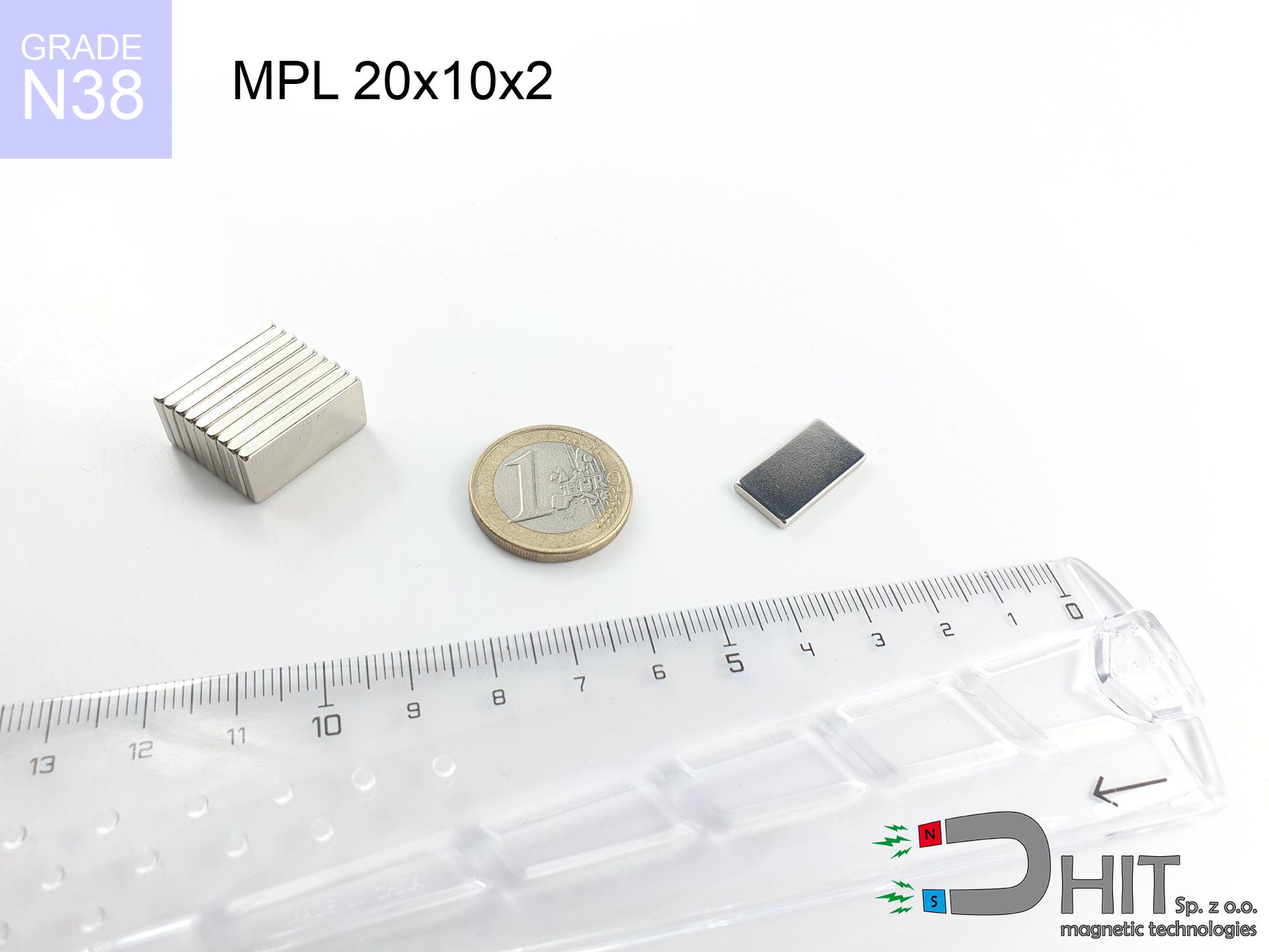
MPL 20x10x2 / N38 - lamellar magnet
lamellar magnet
Catalog no 020127
GTIN/EAN: 5906301811336
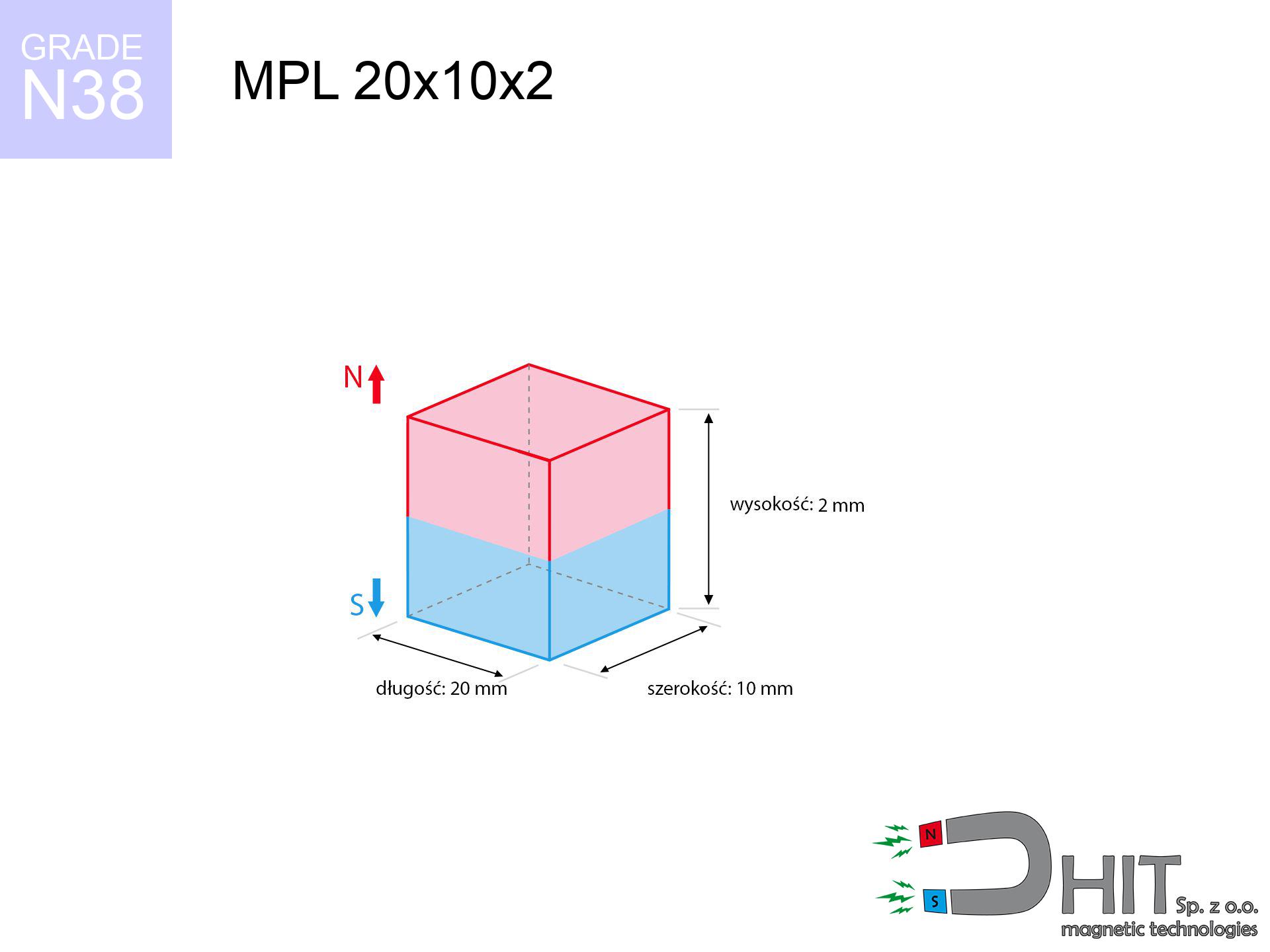
- length
- 20 mm [±0,1 mm]
- Width
- 10 mm [±0,1 mm]
- Height
- 2 mm [±0,1 mm]
- Weight
- 3 g
- Magnetization Direction
- ↑ axial
- Coating
- [NiCuNi] Nickel
How we measure these parameters — certificates and measurements
1.250 zł net / pcs
1.538 zł with VAT (23% VAT) / pcs
bulk discounts:
Need more?Frequently asked questions
What pull rating should I choose for a workshop block magnet?
Are block neodymium magnets available in more durable versions?
How should I choose block magnets for mounting a structure?
Engineering report for this magnet
Full PDF analysis: pull and shear force, effect of distance, temperature and plate thickness, safety distances and the demagnetization curve.
Call us now
+48 888 99 98 98
alternatively let us know using
contact form
the contact section.
Specifications and structure of a neodymium magnet can be estimated using our
power calculator.
Order by 14:00 and we’ll ship today!
Technical details - MPL 20x10x2 / N38 - lamellar magnet
Specification / characteristics - MPL 20x10x2 / N38 - lamellar magnet
| properties | values |
|---|---|
| Cat. no. | 020127 |
| GTIN/EAN | 5906301811336 |
| Production/Distribution | Dhit sp. z o.o. |
| Country of origin | Poland / China / Germany |
| Customs code | 85059029 |
| length | 20 mm [±0,1 mm] |
| Width | 10 mm [±0,1 mm] |
| Height | 2 mm [±0,1 mm] |
| Weight | 3 g |
| Magnetization Direction | ↑ axial |
| Load capacity ~ ? | 1.88 kg / 18.44 N |
| Magnetic Induction ~ ? | 168.24 mT / 1682 Gs |
| Coating | [NiCuNi] Nickel |
| Manufacturing Tolerance | ±0.1 mm |
Magnetic properties of material N38
| properties | values | units |
|---|---|---|
| Remanence Br ? | 12.2-12.6 | kGs |
| Remanence Br ? | 1220-1260 | mT |
| Coercivity bHc ? | 10.8-11.5 | kOe |
| Coercivity bHc ? | 860-915 | kA/m |
| Intrinsic coercivity iHc | ≥ 12 | kOe |
| Intrinsic coercivity iHc | ≥ 955 | kA/m |
| Energy product BHmax ? | 36-38 | BH max MGOe |
| Energy product BHmax ? | 287-303 | BH max KJ/m |
| Maximum working temperature ? | ≤ 80 | °C |
Physical properties of sintered neodymium magnets Nd2Fe14B at 20°C
| properties | values | units |
|---|---|---|
| Vickers hardness | ≥550 | Hv |
| Density | ≥7.4 | g/cm3 |
| Curie Temperature TC | 310 | °C |
| Curie Temperature TF | 590 | °F |
| Specific resistance | 150 | μΩ⋅cm |
| Bending strength | 250 | MPa |
| Compressive strength | 1000~1100 | MPa |
| Thermal expansion parallel (∥) to orientation (M) | (3-4) x 10-6 | °C-1 |
| Thermal expansion perpendicular (⊥) to orientation (M) | -(1-3) x 10-6 | °C-1 |
| Young's modulus | 1.7 x 10⁴ | kg/mm² |
Technical simulation of the assembly - data
Presented values represent the outcome of a mathematical calculation. Values were calculated on models for the material Nd2Fe14B. Actual performance may deviate from the simulation results. Please consider these data as a supplementary guide for designers.
Table 1: Static pull force (force vs gap) - characteristics
MPL 20x10x2 / N38
| Distance (mm) | Induction (Gauss) / mT | Pull Force (kg/lbs/g/N) | Risk Status |
|---|---|---|---|
| 0 mm |
1682 Gs
168.2 mT
|
1.88 kg / 4.14 pounds
1880.0 g / 18.4 N
|
safe |
| 1 mm |
1524 Gs
152.4 mT
|
1.54 kg / 3.40 pounds
1544.3 g / 15.1 N
|
safe |
| 2 mm |
1316 Gs
131.6 mT
|
1.15 kg / 2.54 pounds
1150.1 g / 11.3 N
|
safe |
| 3 mm |
1101 Gs
110.1 mT
|
0.81 kg / 1.78 pounds
806.0 g / 7.9 N
|
safe |
| 5 mm |
744 Gs
74.4 mT
|
0.37 kg / 0.81 pounds
367.6 g / 3.6 N
|
safe |
| 10 mm |
288 Gs
28.8 mT
|
0.06 kg / 0.12 pounds
55.1 g / 0.5 N
|
safe |
| 15 mm |
129 Gs
12.9 mT
|
0.01 kg / 0.02 pounds
11.1 g / 0.1 N
|
safe |
| 20 mm |
66 Gs
6.6 mT
|
0.00 kg / 0.01 pounds
2.9 g / 0.0 N
|
safe |
| 30 mm |
23 Gs
2.3 mT
|
0.00 kg / 0.00 pounds
0.4 g / 0.0 N
|
safe |
| 50 mm |
6 Gs
0.6 mT
|
0.00 kg / 0.00 pounds
0.0 g / 0.0 N
|
safe |
Table 2: Slippage force (wall)
MPL 20x10x2 / N38
| Distance (mm) | Friction coefficient | Pull Force (kg/lbs/g/N) |
|---|---|---|
| 0 mm | Stal (~0.2) |
0.38 kg / 0.83 pounds
376.0 g / 3.7 N
|
| 1 mm | Stal (~0.2) |
0.31 kg / 0.68 pounds
308.0 g / 3.0 N
|
| 2 mm | Stal (~0.2) |
0.23 kg / 0.51 pounds
230.0 g / 2.3 N
|
| 3 mm | Stal (~0.2) |
0.16 kg / 0.36 pounds
162.0 g / 1.6 N
|
| 5 mm | Stal (~0.2) |
0.07 kg / 0.16 pounds
74.0 g / 0.7 N
|
| 10 mm | Stal (~0.2) |
0.01 kg / 0.03 pounds
12.0 g / 0.1 N
|
| 15 mm | Stal (~0.2) |
0.00 kg / 0.00 pounds
2.0 g / 0.0 N
|
| 20 mm | Stal (~0.2) |
0.00 kg / 0.00 pounds
0.0 g / 0.0 N
|
| 30 mm | Stal (~0.2) |
0.00 kg / 0.00 pounds
0.0 g / 0.0 N
|
| 50 mm | Stal (~0.2) |
0.00 kg / 0.00 pounds
0.0 g / 0.0 N
|
Table 3: Wall mounting (shearing) - vertical pull
MPL 20x10x2 / N38
| Surface type | Friction coefficient / % Mocy | Max load (kg/lbs/g/N) |
|---|---|---|
| Raw steel |
µ = 0.3
30% Nominalnej Siły
|
0.56 kg / 1.24 pounds
564.0 g / 5.5 N
|
| Painted steel (standard) |
µ = 0.2
20% Nominalnej Siły
|
0.38 kg / 0.83 pounds
376.0 g / 3.7 N
|
| Oily/slippery steel |
µ = 0.1
10% Nominalnej Siły
|
0.19 kg / 0.41 pounds
188.0 g / 1.8 N
|
| Magnet with anti-slip rubber |
µ = 0.5
50% Nominalnej Siły
|
0.94 kg / 2.07 pounds
940.0 g / 9.2 N
|
Table 4: Material efficiency (saturation) - power losses
MPL 20x10x2 / N38
| Steel thickness (mm) | % power | Real pull force (kg/lbs/g/N) |
|---|---|---|
| 0.5 mm |
|
0.19 kg / 0.41 pounds
188.0 g / 1.8 N
|
| 1 mm |
|
0.47 kg / 1.04 pounds
470.0 g / 4.6 N
|
| 2 mm |
|
0.94 kg / 2.07 pounds
940.0 g / 9.2 N
|
| 3 mm |
|
1.41 kg / 3.11 pounds
1410.0 g / 13.8 N
|
| 5 mm |
|
1.88 kg / 4.14 pounds
1880.0 g / 18.4 N
|
| 10 mm |
|
1.88 kg / 4.14 pounds
1880.0 g / 18.4 N
|
| 11 mm |
|
1.88 kg / 4.14 pounds
1880.0 g / 18.4 N
|
| 12 mm |
|
1.88 kg / 4.14 pounds
1880.0 g / 18.4 N
|
Table 5: Thermal resistance (stability) - thermal limit
MPL 20x10x2 / N38
| Ambient temp. (°C) | Power loss | Remaining pull (kg/lbs/g/N) | Status |
|---|---|---|---|
| 20 °C | 0.0% |
1.88 kg / 4.14 pounds
1880.0 g / 18.4 N
|
OK |
| 40 °C | -2.2% |
1.84 kg / 4.05 pounds
1838.6 g / 18.0 N
|
OK |
| 60 °C | -4.4% |
1.80 kg / 3.96 pounds
1797.3 g / 17.6 N
|
|
| 80 °C | -6.6% |
1.76 kg / 3.87 pounds
1755.9 g / 17.2 N
|
|
| 100 °C | -28.8% |
1.34 kg / 2.95 pounds
1338.6 g / 13.1 N
|
Table 6: Magnet-Magnet interaction (attraction) - field collision
MPL 20x10x2 / N38
| Gap (mm) | Attraction (kg/lbs) (N-S) | Shear Strength (kg/lbs/g/N) | Repulsion (kg/lbs) (N-N) |
|---|---|---|---|
| 0 mm |
3.49 kg / 7.69 pounds
2 995 Gs
|
0.52 kg / 1.15 pounds
523 g / 5.1 N
|
N/A |
| 1 mm |
3.21 kg / 7.08 pounds
3 227 Gs
|
0.48 kg / 1.06 pounds
481 g / 4.7 N
|
2.89 kg / 6.37 pounds
~0 Gs
|
| 2 mm |
2.87 kg / 6.32 pounds
3 049 Gs
|
0.43 kg / 0.95 pounds
430 g / 4.2 N
|
2.58 kg / 5.69 pounds
~0 Gs
|
| 3 mm |
2.50 kg / 5.51 pounds
2 846 Gs
|
0.37 kg / 0.83 pounds
375 g / 3.7 N
|
2.25 kg / 4.95 pounds
~0 Gs
|
| 5 mm |
1.80 kg / 3.96 pounds
2 414 Gs
|
0.27 kg / 0.59 pounds
269 g / 2.6 N
|
1.62 kg / 3.56 pounds
~0 Gs
|
| 10 mm |
0.68 kg / 1.50 pounds
1 487 Gs
|
0.10 kg / 0.23 pounds
102 g / 1.0 N
|
0.61 kg / 1.35 pounds
~0 Gs
|
| 20 mm |
0.10 kg / 0.23 pounds
576 Gs
|
0.02 kg / 0.03 pounds
15 g / 0.2 N
|
0.09 kg / 0.20 pounds
~0 Gs
|
| 50 mm |
0.00 kg / 0.00 pounds
76 Gs
|
0.00 kg / 0.00 pounds
0 g / 0.0 N
|
0.00 kg / 0.00 pounds
~0 Gs
|
| 60 mm |
0.00 kg / 0.00 pounds
47 Gs
|
0.00 kg / 0.00 pounds
0 g / 0.0 N
|
0.00 kg / 0.00 pounds
~0 Gs
|
| 70 mm |
0.00 kg / 0.00 pounds
31 Gs
|
0.00 kg / 0.00 pounds
0 g / 0.0 N
|
0.00 kg / 0.00 pounds
~0 Gs
|
| 80 mm |
0.00 kg / 0.00 pounds
21 Gs
|
0.00 kg / 0.00 pounds
0 g / 0.0 N
|
0.00 kg / 0.00 pounds
~0 Gs
|
| 90 mm |
0.00 kg / 0.00 pounds
15 Gs
|
0.00 kg / 0.00 pounds
0 g / 0.0 N
|
0.00 kg / 0.00 pounds
~0 Gs
|
| 100 mm |
0.00 kg / 0.00 pounds
11 Gs
|
0.00 kg / 0.00 pounds
0 g / 0.0 N
|
0.00 kg / 0.00 pounds
~0 Gs
|
Table 7: Protective zones (implants) - precautionary measures
MPL 20x10x2 / N38
| Object / Device | Limit (Gauss) / mT | Safe distance |
|---|---|---|
| Pacemaker | 5 Gs (0.5 mT) | 5.5 cm |
| Hearing aid | 10 Gs (1.0 mT) | 4.5 cm |
| Mechanical watch | 20 Gs (2.0 mT) | 3.5 cm |
| Phone / Smartphone | 40 Gs (4.0 mT) | 2.5 cm |
| Car key | 50 Gs (5.0 mT) | 2.5 cm |
| Payment card | 400 Gs (40.0 mT) | 1.0 cm |
| HDD hard drive | 600 Gs (60.0 mT) | 1.0 cm |
Table 8: Dynamics (cracking risk) - warning
MPL 20x10x2 / N38
| Start from (mm) | Speed (km/h) | Energy (J) | Predicted outcome |
|---|---|---|---|
| 10 mm |
22.55 km/h
(6.26 m/s)
|
0.06 J | |
| 30 mm |
22.87 km/h
(6.35 m/s)
|
0.06 J | |
| 50 mm |
22.86 km/h
(6.35 m/s)
|
0.06 J | |
| 100 mm |
22.88 km/h
(6.36 m/s)
|
0.06 J |
Table 9: Coating parameters (durability)
MPL 20x10x2 / N38
| Technical parameter | Value / Description |
|---|---|
| Coating type | [NiCuNi] Nickel |
| Layer structure | Nickel - Copper - Nickel |
| Layer thickness | 10-20 µm |
| Salt spray test (SST) ? | 24 h |
| Recommended environment | Indoors only (dry) |
Table 10: Electrical data (Flux)
MPL 20x10x2 / N38
| Parameter | Value | SI Unit / Description |
|---|---|---|
| Magnetic Flux | 3 825 Mx | 38.2 µWb |
| Pc Coefficient | 0.19 | Low (Flat) |
Table 11: Underwater work (magnet fishing)
MPL 20x10x2 / N38
| Environment | Effective steel pull | Effect |
|---|---|---|
| Air (land) | 1.88 kg | Standard |
| Water (riverbed) |
2.15 kg
(+0.27 kg buoyancy gain)
|
+14.5% |
1. Sliding resistance
*Warning: On a vertical wall, the magnet retains merely ~20% of its nominal pull.
2. Steel thickness impact
*Thin metal sheet (e.g. computer case) drastically reduces the holding force.
3. Thermal stability
N38: the maximum material working temperature is 80°C. Permitted conditions also depend on the shape and magnetic circuit.
4. Demagnetization curve and operating point (B-H)
chart generated for the permeance coefficient Pc (Permeance Coefficient) = 0.19
The chart above illustrates the magnetic characteristics of the material within the second quadrant of the hysteresis loop. The solid red line represents the demagnetization curve (material potential), while the dashed blue line is the load line based on the magnet's geometry. The Pc (Permeance Coefficient), also known as the load line slope, is a dimensionless value that describes the relationship between the magnet's shape and its magnetic stability. The intersection of these two lines (the black dot) is the operating point — it determines the actual magnetic flux density generated by the magnet in this specific configuration. A higher Pc value means the magnet is more 'slender' (tall relative to its area), resulting in a higher operating point and better resistance to irreversible demagnetization caused by external fields or temperature. A value of 0.42 is relatively low (typical for flat magnets), meaning the operating point is closer to the 'knee' of the curve — caution is advised when operating at temperatures near the maximum limit to avoid strength loss.
Elemental analysis
| iron (Fe) | 64% – 68% |
| neodymium (Nd) | 29% – 32% |
| boron (B) | 1.1% – 1.2% |
| dysprosium (Dy) | 0.5% – 2.0% |
| coating (Ni-Cu-Ni) | < 0.05% |
Environmental data
| recyclability (EoL) | 100% |
| recycled raw materials | ~10% (pre-cons) |
| carbon footprint | low / zredukowany |
| waste code (EWC) | 16 02 16 |
Other offers

![SM 32x425 [2xM8] / N42 - magnetic separator](https://cdn3.dhit.pl/graphics/products/sm-32x425-2xm8-woj.jpg "SM 32x425 [2xM8] / N42 - magnetic separator")
Advantages and disadvantages of neodymium magnets.
Pros
- They retain full power for around 10 years – the drop is just ~1% (based on simulations),
- Neodymium magnets are distinguished by exceptionally resistant to magnetic field loss caused by magnetic disturbances,
- A magnet with a smooth gold surface looks better,
- The surface of neodymium magnets generates a intense magnetic field – this is a key feature,
- Neodymium magnets are characterized by extremely high magnetic induction on the magnet surface and can function (depending on the form) even at a temperature of 230°C or more...
- Thanks to modularity in designing and the ability to adapt to specific needs,
- Universal use in advanced technology sectors – they are commonly used in hard drives, motor assemblies, advanced medical instruments, and other advanced devices.
- Thanks to efficiency per cm³, small magnets offer high operating force, in miniature format,
Weaknesses
- They are fragile upon too strong impacts. To avoid cracks, it is worth securing magnets in special housings. Such protection not only shields the magnet but also improves its resistance to damage
- Do not exceed this material temperature limit: 80°C. Overheating may permanently weaken the magnet.
- Magnets exposed to a humid environment can corrode. Therefore while using outdoors, we recommend using waterproof magnets made of rubber, plastic or other material resistant to moisture
- Due to limitations in realizing nuts and complex forms in magnets, we propose using a housing - magnetic mount.
- Potential hazard related to microscopic parts of magnets pose a threat, in case of ingestion, which is particularly important in the context of child health protection. It is also worth noting that small components of these magnets are able to be problematic in diagnostics medical in case of swallowing.
- Due to complex production process, their price exceeds standard values,
Holding force characteristics
Maximum lifting capacity of the magnet – what contributes to it?
- on a base made of mild steel, effectively closing the magnetic field
- with a thickness of at least 10 mm
- with an ground contact surface
- without the slightest clearance between the magnet and steel
- during detachment in a direction vertical to the plane
- at standard ambient temperature
Impact of factors on magnetic holding capacity in practice
- Space between magnet and steel – even a fraction of a millimeter of distance (caused e.g. by varnish or unevenness) significantly weakens the magnet efficiency, often by half at just 0.5 mm.
- Force direction – catalog parameter refers to detachment vertically. When slipping, the magnet holds much less (typically approx. 20-30% of maximum force).
- Wall thickness – the thinner the sheet, the weaker the hold. Part of the magnetic field passes through the material instead of converting into lifting capacity.
- Metal type – not every steel reacts the same. Alloy additives weaken the attraction effect.
- Surface finish – ideal contact is possible only on smooth steel. Rough texture reduce the real contact area, weakening the magnet.
- Thermal conditions – neodymium magnets have a sensitivity to temperature. At higher temperatures they lose power, and in frost gain strength (up to a certain limit).
Holding force was measured on a smooth steel plate of 20 mm thickness, when a perpendicular force was applied, whereas under shearing force the load capacity is reduced by as much as 5 times. In addition, even a minimal clearance between the magnet and the plate decreases the holding force.
Precautions when working with NdFeB magnets
Bone fractures
Big blocks can crush fingers in a fraction of a second. Under no circumstances place your hand betwixt two strong magnets.
Handling rules
Use magnets with awareness. Their huge power can surprise even professionals. Stay alert and respect their force.
Threat to electronics
Data protection: Neodymium magnets can ruin data carriers and delicate electronics (pacemakers, medical aids, mechanical watches).
Implant safety
Life threat: Strong magnets can turn off pacemakers and defibrillators. Do not approach if you have electronic implants.
Product not for children
Neodymium magnets are not suitable for play. Eating multiple magnets can lead to them pinching intestinal walls, which poses a direct threat to life and necessitates immediate surgery.
Eye protection
Protect your eyes. Magnets can explode upon violent connection, launching sharp fragments into the air. We recommend safety glasses.
Thermal limits
Standard neodymium magnets (N-type) lose power when the temperature exceeds 80°C. The loss of strength is permanent.
GPS and phone interference
A powerful magnetic field interferes with the operation of magnetometers in phones and GPS navigation. Maintain magnets near a device to prevent breaking the sensors.
Machining danger
Mechanical processing of NdFeB material carries a risk of fire hazard. Magnetic powder oxidizes rapidly with oxygen and is hard to extinguish.
Allergic reactions
It is widely known that the nickel plating (the usual finish) is a common allergen. If you have an allergy, prevent touching magnets with bare hands or choose versions in plastic housing.
Tabela kosztu i czasu dostawy
Płatność przed wysyłką:

GLS kurier
Przesyłka będzie u Ciebie za 2-3 dni
14.99 ZŁ

InPost Paczkomaty 24/7
Przesyłka będzie u Ciebie za 1-2 dni
12.30 ZŁ
Płatność przy odbiorze (pobranie):
GLS kurier
Przesyłka będzie u Ciebie za 1-2 dni
23.00 ZŁ