


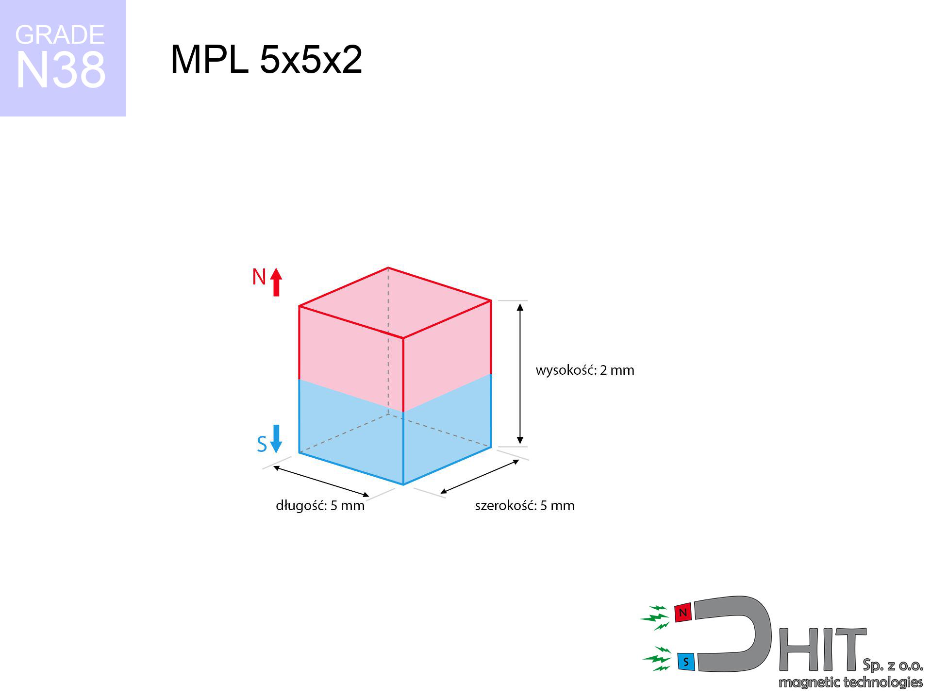
MPL 5x5x2 / N38 - lamellar magnet
lamellar magnet
Catalog no 020173
GTIN/EAN: 5906301811794
- length
- 5 mm [±0,1 mm]
- Width
- 5 mm [±0,1 mm]
- Height
- 2 mm [±0,1 mm]
- Weight
- 0.38 g
- Magnetization Direction
- ↑ axial
- Coating
- [NiCuNi] Nickel
How we measure these parameters — certificates and measurements
0.250 zł net / pcs
0.308 zł with VAT (23% VAT) / pcs
bulk discounts:
Need more?Frequently asked questions
What pull rating should I choose for a workshop block magnet?
Are block neodymium magnets available in more durable versions?
How should I choose block magnets for mounting a structure?
Engineering report for this magnet
Full PDF analysis: pull and shear force, effect of distance, temperature and plate thickness, safety distances and the demagnetization curve.
Call us now
+48 888 99 98 98
alternatively let us know using
contact form
the contact section.
Specifications and structure of a neodymium magnet can be estimated using our
power calculator.
Order by 14:00 and we’ll ship today!
Technical details - MPL 5x5x2 / N38 - lamellar magnet
Specification / characteristics - MPL 5x5x2 / N38 - lamellar magnet
| properties | values |
|---|---|
| Cat. no. | 020173 |
| GTIN/EAN | 5906301811794 |
| Production/Distribution | Dhit sp. z o.o. |
| Country of origin | Poland / China / Germany |
| Customs code | 85059029 |
| length | 5 mm [±0,1 mm] |
| Width | 5 mm [±0,1 mm] |
| Height | 2 mm [±0,1 mm] |
| Weight | 0.38 g |
| Magnetization Direction | ↑ axial |
| Load capacity ~ ? | 0.77 kg / 7.57 N |
| Magnetic Induction ~ ? | 360.52 mT / 3605 Gs |
| Coating | [NiCuNi] Nickel |
| Manufacturing Tolerance | ±0.1 mm |
Magnetic properties of material N38
| properties | values | units |
|---|---|---|
| Remanence Br ? | 12.2-12.6 | kGs |
| Remanence Br ? | 1220-1260 | mT |
| Coercivity bHc ? | 10.8-11.5 | kOe |
| Coercivity bHc ? | 860-915 | kA/m |
| Intrinsic coercivity iHc | ≥ 12 | kOe |
| Intrinsic coercivity iHc | ≥ 955 | kA/m |
| Energy product BHmax ? | 36-38 | BH max MGOe |
| Energy product BHmax ? | 287-303 | BH max KJ/m |
| Maximum working temperature ? | ≤ 80 | °C |
Physical properties of sintered neodymium magnets Nd2Fe14B at 20°C
| properties | values | units |
|---|---|---|
| Vickers hardness | ≥550 | Hv |
| Density | ≥7.4 | g/cm3 |
| Curie Temperature TC | 310 | °C |
| Curie Temperature TF | 590 | °F |
| Specific resistance | 150 | μΩ⋅cm |
| Bending strength | 250 | MPa |
| Compressive strength | 1000~1100 | MPa |
| Thermal expansion parallel (∥) to orientation (M) | (3-4) x 10-6 | °C-1 |
| Thermal expansion perpendicular (⊥) to orientation (M) | -(1-3) x 10-6 | °C-1 |
| Young's modulus | 1.7 x 10⁴ | kg/mm² |
Technical simulation of the product - data
These information are the outcome of a physical analysis. Values are based on algorithms for the material Nd2Fe14B. Operational performance may differ from theoretical values. Treat these calculations as a reference point during assembly planning.
Table 1: Static force (force vs gap) - characteristics
MPL 5x5x2 / N38
| Distance (mm) | Induction (Gauss) / mT | Pull Force (kg/lbs/g/N) | Risk Status |
|---|---|---|---|
| 0 mm |
3601 Gs
360.1 mT
|
0.77 kg / 1.70 LBS
770.0 g / 7.6 N
|
safe |
| 1 mm |
2436 Gs
243.6 mT
|
0.35 kg / 0.78 LBS
352.2 g / 3.5 N
|
safe |
| 2 mm |
1464 Gs
146.4 mT
|
0.13 kg / 0.28 LBS
127.3 g / 1.2 N
|
safe |
| 3 mm |
872 Gs
87.2 mT
|
0.05 kg / 0.10 LBS
45.1 g / 0.4 N
|
safe |
| 5 mm |
347 Gs
34.7 mT
|
0.01 kg / 0.02 LBS
7.2 g / 0.1 N
|
safe |
| 10 mm |
68 Gs
6.8 mT
|
0.00 kg / 0.00 LBS
0.3 g / 0.0 N
|
safe |
| 15 mm |
23 Gs
2.3 mT
|
0.00 kg / 0.00 LBS
0.0 g / 0.0 N
|
safe |
| 20 mm |
10 Gs
1.0 mT
|
0.00 kg / 0.00 LBS
0.0 g / 0.0 N
|
safe |
| 30 mm |
3 Gs
0.3 mT
|
0.00 kg / 0.00 LBS
0.0 g / 0.0 N
|
safe |
| 50 mm |
1 Gs
0.1 mT
|
0.00 kg / 0.00 LBS
0.0 g / 0.0 N
|
safe |
Table 2: Sliding load (vertical surface)
MPL 5x5x2 / N38
| Distance (mm) | Friction coefficient | Pull Force (kg/lbs/g/N) |
|---|---|---|
| 0 mm | Stal (~0.2) |
0.15 kg / 0.34 LBS
154.0 g / 1.5 N
|
| 1 mm | Stal (~0.2) |
0.07 kg / 0.15 LBS
70.0 g / 0.7 N
|
| 2 mm | Stal (~0.2) |
0.03 kg / 0.06 LBS
26.0 g / 0.3 N
|
| 3 mm | Stal (~0.2) |
0.01 kg / 0.02 LBS
10.0 g / 0.1 N
|
| 5 mm | Stal (~0.2) |
0.00 kg / 0.00 LBS
2.0 g / 0.0 N
|
| 10 mm | Stal (~0.2) |
0.00 kg / 0.00 LBS
0.0 g / 0.0 N
|
| 15 mm | Stal (~0.2) |
0.00 kg / 0.00 LBS
0.0 g / 0.0 N
|
| 20 mm | Stal (~0.2) |
0.00 kg / 0.00 LBS
0.0 g / 0.0 N
|
| 30 mm | Stal (~0.2) |
0.00 kg / 0.00 LBS
0.0 g / 0.0 N
|
| 50 mm | Stal (~0.2) |
0.00 kg / 0.00 LBS
0.0 g / 0.0 N
|
Table 3: Vertical assembly (sliding) - behavior on slippery surfaces
MPL 5x5x2 / N38
| Surface type | Friction coefficient / % Mocy | Max load (kg/lbs/g/N) |
|---|---|---|
| Raw steel |
µ = 0.3
30% Nominalnej Siły
|
0.23 kg / 0.51 LBS
231.0 g / 2.3 N
|
| Painted steel (standard) |
µ = 0.2
20% Nominalnej Siły
|
0.15 kg / 0.34 LBS
154.0 g / 1.5 N
|
| Oily/slippery steel |
µ = 0.1
10% Nominalnej Siły
|
0.08 kg / 0.17 LBS
77.0 g / 0.8 N
|
| Magnet with anti-slip rubber |
µ = 0.5
50% Nominalnej Siły
|
0.39 kg / 0.85 LBS
385.0 g / 3.8 N
|
Table 4: Steel thickness (substrate influence) - power losses
MPL 5x5x2 / N38
| Steel thickness (mm) | % power | Real pull force (kg/lbs/g/N) |
|---|---|---|
| 0.5 mm |
|
0.08 kg / 0.17 LBS
77.0 g / 0.8 N
|
| 1 mm |
|
0.19 kg / 0.42 LBS
192.5 g / 1.9 N
|
| 2 mm |
|
0.39 kg / 0.85 LBS
385.0 g / 3.8 N
|
| 3 mm |
|
0.58 kg / 1.27 LBS
577.5 g / 5.7 N
|
| 5 mm |
|
0.77 kg / 1.70 LBS
770.0 g / 7.6 N
|
| 10 mm |
|
0.77 kg / 1.70 LBS
770.0 g / 7.6 N
|
| 11 mm |
|
0.77 kg / 1.70 LBS
770.0 g / 7.6 N
|
| 12 mm |
|
0.77 kg / 1.70 LBS
770.0 g / 7.6 N
|
Table 5: Thermal stability (material behavior) - thermal limit
MPL 5x5x2 / N38
| Ambient temp. (°C) | Power loss | Remaining pull (kg/lbs/g/N) | Status |
|---|---|---|---|
| 20 °C | 0.0% |
0.77 kg / 1.70 LBS
770.0 g / 7.6 N
|
OK |
| 40 °C | -2.2% |
0.75 kg / 1.66 LBS
753.1 g / 7.4 N
|
OK |
| 60 °C | -4.4% |
0.74 kg / 1.62 LBS
736.1 g / 7.2 N
|
|
| 80 °C | -6.6% |
0.72 kg / 1.59 LBS
719.2 g / 7.1 N
|
|
| 100 °C | -28.8% |
0.55 kg / 1.21 LBS
548.2 g / 5.4 N
|
Table 6: Magnet-Magnet interaction (repulsion) - field collision
MPL 5x5x2 / N38
| Gap (mm) | Attraction (kg/lbs) (N-S) | Sliding Force (kg/lbs/g/N) | Repulsion (kg/lbs) (N-N) |
|---|---|---|---|
| 0 mm |
2.00 kg / 4.41 LBS
5 058 Gs
|
0.30 kg / 0.66 LBS
300 g / 2.9 N
|
N/A |
| 1 mm |
1.42 kg / 3.13 LBS
6 070 Gs
|
0.21 kg / 0.47 LBS
213 g / 2.1 N
|
1.28 kg / 2.82 LBS
~0 Gs
|
| 2 mm |
0.91 kg / 2.02 LBS
4 871 Gs
|
0.14 kg / 0.30 LBS
137 g / 1.3 N
|
0.82 kg / 1.81 LBS
~0 Gs
|
| 3 mm |
0.56 kg / 1.23 LBS
3 801 Gs
|
0.08 kg / 0.18 LBS
83 g / 0.8 N
|
0.50 kg / 1.10 LBS
~0 Gs
|
| 5 mm |
0.20 kg / 0.43 LBS
2 254 Gs
|
0.03 kg / 0.06 LBS
29 g / 0.3 N
|
0.18 kg / 0.39 LBS
~0 Gs
|
| 10 mm |
0.02 kg / 0.04 LBS
695 Gs
|
0.00 kg / 0.01 LBS
3 g / 0.0 N
|
0.02 kg / 0.04 LBS
~0 Gs
|
| 20 mm |
0.00 kg / 0.00 LBS
136 Gs
|
0.00 kg / 0.00 LBS
0 g / 0.0 N
|
0.00 kg / 0.00 LBS
~0 Gs
|
| 50 mm |
0.00 kg / 0.00 LBS
11 Gs
|
0.00 kg / 0.00 LBS
0 g / 0.0 N
|
0.00 kg / 0.00 LBS
~0 Gs
|
| 60 mm |
0.00 kg / 0.00 LBS
7 Gs
|
0.00 kg / 0.00 LBS
0 g / 0.0 N
|
0.00 kg / 0.00 LBS
~0 Gs
|
| 70 mm |
0.00 kg / 0.00 LBS
4 Gs
|
0.00 kg / 0.00 LBS
0 g / 0.0 N
|
0.00 kg / 0.00 LBS
~0 Gs
|
| 80 mm |
0.00 kg / 0.00 LBS
3 Gs
|
0.00 kg / 0.00 LBS
0 g / 0.0 N
|
0.00 kg / 0.00 LBS
~0 Gs
|
| 90 mm |
0.00 kg / 0.00 LBS
2 Gs
|
0.00 kg / 0.00 LBS
0 g / 0.0 N
|
0.00 kg / 0.00 LBS
~0 Gs
|
| 100 mm |
0.00 kg / 0.00 LBS
1 Gs
|
0.00 kg / 0.00 LBS
0 g / 0.0 N
|
0.00 kg / 0.00 LBS
~0 Gs
|
Table 7: Hazards (electronics) - warnings
MPL 5x5x2 / N38
| Object / Device | Limit (Gauss) / mT | Safe distance |
|---|---|---|
| Pacemaker | 5 Gs (0.5 mT) | 3.0 cm |
| Hearing aid | 10 Gs (1.0 mT) | 2.5 cm |
| Timepiece | 20 Gs (2.0 mT) | 2.0 cm |
| Mobile device | 40 Gs (4.0 mT) | 1.5 cm |
| Remote | 50 Gs (5.0 mT) | 1.5 cm |
| Payment card | 400 Gs (40.0 mT) | 0.5 cm |
| HDD hard drive | 600 Gs (60.0 mT) | 0.5 cm |
Table 8: Impact energy (kinetic energy) - collision effects
MPL 5x5x2 / N38
| Start from (mm) | Speed (km/h) | Energy (J) | Predicted outcome |
|---|---|---|---|
| 10 mm |
24.62 km/h
(6.84 m/s)
|
0.01 J | |
| 30 mm |
24.63 km/h
(6.84 m/s)
|
0.01 J | |
| 50 mm |
24.62 km/h
(6.84 m/s)
|
0.01 J | |
| 100 mm |
24.63 km/h
(6.84 m/s)
|
0.01 J |
Table 9: Coating parameters (durability)
MPL 5x5x2 / N38
| Technical parameter | Value / Description |
|---|---|
| Coating type | [NiCuNi] Nickel |
| Layer structure | Nickel - Copper - Nickel |
| Layer thickness | 10-20 µm |
| Salt spray test (SST) ? | 24 h |
| Recommended environment | Indoors only (dry) |
Table 10: Construction data (Pc)
MPL 5x5x2 / N38
| Parameter | Value | SI Unit / Description |
|---|---|---|
| Magnetic Flux | 940 Mx | 9.4 µWb |
| Pc Coefficient | 0.46 | Low (Flat) |
Table 11: Underwater work (magnet fishing)
MPL 5x5x2 / N38
| Environment | Effective steel pull | Effect |
|---|---|---|
| Air (land) | 0.77 kg | Standard |
| Water (riverbed) |
0.88 kg
(+0.11 kg buoyancy gain)
|
+14.5% |
1. Vertical hold
*Caution: On a vertical wall, the magnet retains merely approx. 20-30% of its nominal pull.
2. Plate thickness effect
*Thin steel (e.g. 0.5mm PC case) drastically limits the holding force.
3. Power loss vs temp
N38: the maximum material working temperature is 80°C. Permitted conditions also depend on the shape and magnetic circuit.
4. Demagnetization curve and operating point (B-H)
chart generated for the permeance coefficient Pc (Permeance Coefficient) = 0.46
This simulation demonstrates the magnetic stability of the selected magnet under specific geometric conditions. The solid red line represents the demagnetization curve (material potential), while the dashed blue line is the load line based on the magnet's geometry. The Pc (Permeance Coefficient), also known as the load line slope, is a dimensionless value that describes the relationship between the magnet's shape and its magnetic stability. The intersection of these two lines (the black dot) is the operating point — it determines the actual magnetic flux density generated by the magnet in this specific configuration. A higher Pc value means the magnet is more 'slender' (tall relative to its area), resulting in a higher operating point and better resistance to irreversible demagnetization caused by external fields or temperature. A value of 0.42 is relatively low (typical for flat magnets), meaning the operating point is closer to the 'knee' of the curve — caution is advised when operating at temperatures near the maximum limit to avoid strength loss.
Elemental analysis
| iron (Fe) | 64% – 68% |
| neodymium (Nd) | 29% – 32% |
| boron (B) | 1.1% – 1.2% |
| dysprosium (Dy) | 0.5% – 2.0% |
| coating (Ni-Cu-Ni) | < 0.05% |
Sustainability
| recyclability (EoL) | 100% |
| recycled raw materials | ~10% (pre-cons) |
| carbon footprint | low / zredukowany |
| waste code (EWC) | 16 02 16 |
Other deals

![UMP 94x28 [3xM10] GW F300 GOLD Lina / N38 - search holder](https://cdn3.dhit.pl/graphics/products/ump-94x28-m10-gw-f300-+lina-kac.jpg "UMP 94x28 [3xM10] GW F300 GOLD Lina / N38 - search holder")
Pros and cons of neodymium magnets.
Advantages
- They virtually do not lose power, because even after 10 years the performance loss is only ~1% (according to literature),
- Neodymium magnets prove to be exceptionally resistant to loss of magnetic properties caused by external magnetic fields,
- Thanks to the reflective finish, the layer of nickel, gold, or silver gives an aesthetic appearance,
- Neodymium magnets deliver maximum magnetic induction on a contact point, which allows for strong attraction,
- Due to their durability and thermal resistance, neodymium magnets can operate (depending on the form) even at high temperatures reaching 230°C or more...
- Possibility of exact shaping as well as adjusting to complex needs,
- Wide application in electronics industry – they are commonly used in data components, brushless drives, medical equipment, and modern systems.
- Relatively small size with high pulling force – neodymium magnets offer high power in tiny dimensions, which makes them useful in compact constructions
Disadvantages
- At strong impacts they can break, therefore we advise placing them in special holders. A metal housing provides additional protection against damage and increases the magnet's durability.
- Do not exceed this material temperature limit: 80°C. Overheating may permanently weaken the magnet.
- Magnets exposed to a humid environment can corrode. Therefore when using outdoors, we advise using waterproof magnets made of rubber, plastic or other material resistant to moisture
- We recommend casing - magnetic mount, due to difficulties in creating threads inside the magnet and complex shapes.
- Possible danger related to microscopic parts of magnets can be dangerous, when accidentally swallowed, which becomes key in the context of child safety. Furthermore, tiny parts of these magnets can be problematic in diagnostics medical in case of swallowing.
- With mass production the cost of neodymium magnets is economically unviable,
Lifting parameters
Breakaway strength of the magnet in ideal conditions – what contributes to it?
- on a plate made of mild steel, effectively closing the magnetic field
- possessing a massiveness of min. 10 mm to avoid saturation
- characterized by smoothness
- with zero gap (no impurities)
- under perpendicular force direction (90-degree angle)
- in temp. approx. 20°C
Practical aspects of lifting capacity – factors
- Gap between magnet and steel – every millimeter of separation (caused e.g. by varnish or dirt) significantly weakens the magnet efficiency, often by half at just 0.5 mm.
- Force direction – catalog parameter refers to detachment vertically. When slipping, the magnet holds significantly lower power (often approx. 20-30% of nominal force).
- Substrate thickness – to utilize 100% power, the steel must be sufficiently thick. Thin sheet limits the lifting capacity (the magnet "punches through" it).
- Chemical composition of the base – low-carbon steel attracts best. Alloy admixtures decrease magnetic permeability and holding force.
- Surface structure – the more even the surface, the larger the contact zone and higher the lifting capacity. Roughness acts like micro-gaps.
- Thermal factor – high temperature weakens magnetic field. Too high temperature can permanently damage the magnet.
Lifting capacity testing was carried out on a smooth plate of suitable thickness, under perpendicular forces, however under attempts to slide the magnet the lifting capacity is smaller. Moreover, even a minimal clearance between the magnet and the plate decreases the lifting capacity.
Precautions when working with NdFeB magnets
Threat to electronics
Avoid bringing magnets near a wallet, computer, or screen. The magnetism can permanently damage these devices and erase data from cards.
Handling rules
Before use, read the rules. Sudden snapping can destroy the magnet or injure your hand. Think ahead.
Nickel coating and allergies
A percentage of the population experience a sensitization to Ni, which is the typical protective layer for neodymium magnets. Prolonged contact may cause a rash. We recommend wear safety gloves.
Compass and GPS
Note: neodymium magnets generate a field that interferes with sensitive sensors. Maintain a separation from your phone, tablet, and GPS.
Do not overheat magnets
Regular neodymium magnets (N-type) lose power when the temperature exceeds 80°C. This process is irreversible.
Dust is flammable
Drilling and cutting of neodymium magnets poses a fire hazard. Neodymium dust reacts violently with oxygen and is hard to extinguish.
Pinching danger
Large magnets can smash fingers instantly. Never place your hand betwixt two strong magnets.
Do not give to children
Neodymium magnets are not suitable for play. Accidental ingestion of multiple magnets may result in them connecting inside the digestive tract, which constitutes a severe health hazard and requires immediate surgery.
Warning for heart patients
For implant holders: Strong magnetic fields affect medical devices. Keep at least 30 cm distance or ask another person to work with the magnets.
Shattering risk
Despite metallic appearance, the material is brittle and cannot withstand shocks. Do not hit, as the magnet may crumble into hazardous fragments.
Tabela kosztu i czasu dostawy
Płatność przed wysyłką:

GLS kurier
Przesyłka będzie u Ciebie za 2-3 dni
14.99 ZŁ

InPost Paczkomaty 24/7
Przesyłka będzie u Ciebie za 1-2 dni
12.30 ZŁ
Płatność przy odbiorze (pobranie):
GLS kurier
Przesyłka będzie u Ciebie za 1-2 dni
23.00 ZŁ