


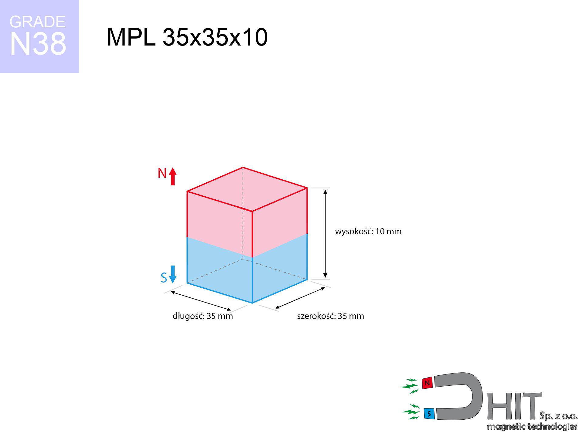
MPL 35x35x10 / N38 - lamellar magnet
lamellar magnet
Catalog no 020144
GTIN/EAN: 5906301811503
- length
- 35 mm [±0,1 mm]
- Width
- 35 mm [±0,1 mm]
- Height
- 10 mm [±0,1 mm]
- Weight
- 91.88 g
- Magnetization Direction
- ↑ axial
- Coating
- [NiCuNi] Nickel
How we measure these parameters — certificates and measurements
28.54 zł net / pcs
35.10 zł with VAT (23% VAT) / pcs
bulk discounts:
Need more?Frequently asked questions
What pull rating should I choose for a workshop block magnet?
Are block neodymium magnets available in more durable versions?
How should I choose block magnets for mounting a structure?
Engineering report for this magnet
Full PDF analysis: pull and shear force, effect of distance, temperature and plate thickness, safety distances and the demagnetization curve.
Call us now
+48 888 99 98 98
alternatively let us know using
contact form
the contact section.
Specifications and structure of a neodymium magnet can be estimated using our
power calculator.
Order by 14:00 and we’ll ship today!
Physical properties - MPL 35x35x10 / N38 - lamellar magnet
Specification / characteristics - MPL 35x35x10 / N38 - lamellar magnet
| properties | values |
|---|---|
| Cat. no. | 020144 |
| GTIN/EAN | 5906301811503 |
| Production/Distribution | Dhit sp. z o.o. |
| Country of origin | Poland / China / Germany |
| Customs code | 85059029 |
| length | 35 mm [±0,1 mm] |
| Width | 35 mm [±0,1 mm] |
| Height | 10 mm [±0,1 mm] |
| Weight | 91.88 g |
| Magnetization Direction | ↑ axial |
| Load capacity ~ ? | 26.88 kg / 263.71 N |
| Magnetic Induction ~ ? | 282.90 mT / 2829 Gs |
| Coating | [NiCuNi] Nickel |
| Manufacturing Tolerance | ±0.1 mm |
Magnetic properties of material N38
| properties | values | units |
|---|---|---|
| Remanence Br ? | 12.2-12.6 | kGs |
| Remanence Br ? | 1220-1260 | mT |
| Coercivity bHc ? | 10.8-11.5 | kOe |
| Coercivity bHc ? | 860-915 | kA/m |
| Intrinsic coercivity iHc | ≥ 12 | kOe |
| Intrinsic coercivity iHc | ≥ 955 | kA/m |
| Energy product BHmax ? | 36-38 | BH max MGOe |
| Energy product BHmax ? | 287-303 | BH max KJ/m |
| Maximum working temperature ? | ≤ 80 | °C |
Physical properties of sintered neodymium magnets Nd2Fe14B at 20°C
| properties | values | units |
|---|---|---|
| Vickers hardness | ≥550 | Hv |
| Density | ≥7.4 | g/cm3 |
| Curie Temperature TC | 310 | °C |
| Curie Temperature TF | 590 | °F |
| Specific resistance | 150 | μΩ⋅cm |
| Bending strength | 250 | MPa |
| Compressive strength | 1000~1100 | MPa |
| Thermal expansion parallel (∥) to orientation (M) | (3-4) x 10-6 | °C-1 |
| Thermal expansion perpendicular (⊥) to orientation (M) | -(1-3) x 10-6 | °C-1 |
| Young's modulus | 1.7 x 10⁴ | kg/mm² |
Technical simulation of the assembly - technical parameters
Presented information constitute the result of a mathematical analysis. Results are based on models for the class Nd2Fe14B. Operational parameters might slightly differ from theoretical values. Please consider these data as a preliminary roadmap for designers.
Table 1: Static pull force (pull vs distance) - power drop
MPL 35x35x10 / N38
| Distance (mm) | Induction (Gauss) / mT | Pull Force (kg/lbs/g/N) | Risk Status |
|---|---|---|---|
| 0 mm |
2829 Gs
282.9 mT
|
26.88 kg / 59.26 lbs
26880.0 g / 263.7 N
|
dangerous! |
| 1 mm |
2727 Gs
272.7 mT
|
24.98 kg / 55.08 lbs
24982.7 g / 245.1 N
|
dangerous! |
| 2 mm |
2613 Gs
261.3 mT
|
22.94 kg / 50.57 lbs
22939.0 g / 225.0 N
|
dangerous! |
| 3 mm |
2491 Gs
249.1 mT
|
20.84 kg / 45.95 lbs
20841.0 g / 204.4 N
|
dangerous! |
| 5 mm |
2232 Gs
223.2 mT
|
16.73 kg / 36.88 lbs
16730.5 g / 164.1 N
|
dangerous! |
| 10 mm |
1600 Gs
160.0 mT
|
8.60 kg / 18.96 lbs
8600.7 g / 84.4 N
|
medium risk |
| 15 mm |
1102 Gs
110.2 mT
|
4.08 kg / 9.00 lbs
4082.9 g / 40.1 N
|
medium risk |
| 20 mm |
757 Gs
75.7 mT
|
1.93 kg / 4.25 lbs
1925.7 g / 18.9 N
|
low risk |
| 30 mm |
376 Gs
37.6 mT
|
0.48 kg / 1.05 lbs
475.7 g / 4.7 N
|
low risk |
| 50 mm |
122 Gs
12.2 mT
|
0.05 kg / 0.11 lbs
49.9 g / 0.5 N
|
low risk |
Table 2: Shear capacity (vertical surface)
MPL 35x35x10 / N38
| Distance (mm) | Friction coefficient | Pull Force (kg/lbs/g/N) |
|---|---|---|
| 0 mm | Stal (~0.2) |
5.38 kg / 11.85 lbs
5376.0 g / 52.7 N
|
| 1 mm | Stal (~0.2) |
5.00 kg / 11.01 lbs
4996.0 g / 49.0 N
|
| 2 mm | Stal (~0.2) |
4.59 kg / 10.11 lbs
4588.0 g / 45.0 N
|
| 3 mm | Stal (~0.2) |
4.17 kg / 9.19 lbs
4168.0 g / 40.9 N
|
| 5 mm | Stal (~0.2) |
3.35 kg / 7.38 lbs
3346.0 g / 32.8 N
|
| 10 mm | Stal (~0.2) |
1.72 kg / 3.79 lbs
1720.0 g / 16.9 N
|
| 15 mm | Stal (~0.2) |
0.82 kg / 1.80 lbs
816.0 g / 8.0 N
|
| 20 mm | Stal (~0.2) |
0.39 kg / 0.85 lbs
386.0 g / 3.8 N
|
| 30 mm | Stal (~0.2) |
0.10 kg / 0.21 lbs
96.0 g / 0.9 N
|
| 50 mm | Stal (~0.2) |
0.01 kg / 0.02 lbs
10.0 g / 0.1 N
|
Table 3: Wall mounting (shearing) - vertical pull
MPL 35x35x10 / N38
| Surface type | Friction coefficient / % Mocy | Max load (kg/lbs/g/N) |
|---|---|---|
| Raw steel |
µ = 0.3
30% Nominalnej Siły
|
8.06 kg / 17.78 lbs
8064.0 g / 79.1 N
|
| Painted steel (standard) |
µ = 0.2
20% Nominalnej Siły
|
5.38 kg / 11.85 lbs
5376.0 g / 52.7 N
|
| Oily/slippery steel |
µ = 0.1
10% Nominalnej Siły
|
2.69 kg / 5.93 lbs
2688.0 g / 26.4 N
|
| Magnet with anti-slip rubber |
µ = 0.5
50% Nominalnej Siły
|
13.44 kg / 29.63 lbs
13440.0 g / 131.8 N
|
Table 4: Material efficiency (saturation) - power losses
MPL 35x35x10 / N38
| Steel thickness (mm) | % power | Real pull force (kg/lbs/g/N) |
|---|---|---|
| 0.5 mm |
|
1.34 kg / 2.96 lbs
1344.0 g / 13.2 N
|
| 1 mm |
|
3.36 kg / 7.41 lbs
3360.0 g / 33.0 N
|
| 2 mm |
|
6.72 kg / 14.82 lbs
6720.0 g / 65.9 N
|
| 3 mm |
|
10.08 kg / 22.22 lbs
10080.0 g / 98.9 N
|
| 5 mm |
|
16.80 kg / 37.04 lbs
16800.0 g / 164.8 N
|
| 10 mm |
|
26.88 kg / 59.26 lbs
26880.0 g / 263.7 N
|
| 11 mm |
|
26.88 kg / 59.26 lbs
26880.0 g / 263.7 N
|
| 12 mm |
|
26.88 kg / 59.26 lbs
26880.0 g / 263.7 N
|
Table 5: Thermal resistance (stability) - thermal limit
MPL 35x35x10 / N38
| Ambient temp. (°C) | Power loss | Remaining pull (kg/lbs/g/N) | Status |
|---|---|---|---|
| 20 °C | 0.0% |
26.88 kg / 59.26 lbs
26880.0 g / 263.7 N
|
OK |
| 40 °C | -2.2% |
26.29 kg / 57.96 lbs
26288.6 g / 257.9 N
|
OK |
| 60 °C | -4.4% |
25.70 kg / 56.65 lbs
25697.3 g / 252.1 N
|
|
| 80 °C | -6.6% |
25.11 kg / 55.35 lbs
25105.9 g / 246.3 N
|
|
| 100 °C | -28.8% |
19.14 kg / 42.19 lbs
19138.6 g / 187.7 N
|
Table 6: Magnet-Magnet interaction (repulsion) - field collision
MPL 35x35x10 / N38
| Gap (mm) | Attraction (kg/lbs) (N-S) | Shear Strength (kg/lbs/g/N) | Repulsion (kg/lbs) (N-N) |
|---|---|---|---|
| 0 mm |
60.43 kg / 133.22 lbs
4 428 Gs
|
9.06 kg / 19.98 lbs
9064 g / 88.9 N
|
N/A |
| 1 mm |
58.36 kg / 128.67 lbs
5 560 Gs
|
8.75 kg / 19.30 lbs
8754 g / 85.9 N
|
52.53 kg / 115.80 lbs
~0 Gs
|
| 2 mm |
56.16 kg / 123.82 lbs
5 454 Gs
|
8.42 kg / 18.57 lbs
8424 g / 82.6 N
|
50.55 kg / 111.44 lbs
~0 Gs
|
| 3 mm |
53.89 kg / 118.81 lbs
5 343 Gs
|
8.08 kg / 17.82 lbs
8084 g / 79.3 N
|
48.50 kg / 106.93 lbs
~0 Gs
|
| 5 mm |
49.22 kg / 108.50 lbs
5 106 Gs
|
7.38 kg / 16.28 lbs
7382 g / 72.4 N
|
44.29 kg / 97.65 lbs
~0 Gs
|
| 10 mm |
37.61 kg / 82.92 lbs
4 463 Gs
|
5.64 kg / 12.44 lbs
5642 g / 55.3 N
|
33.85 kg / 74.63 lbs
~0 Gs
|
| 20 mm |
19.33 kg / 42.63 lbs
3 200 Gs
|
2.90 kg / 6.39 lbs
2900 g / 28.5 N
|
17.40 kg / 38.36 lbs
~0 Gs
|
| 50 mm |
2.10 kg / 4.64 lbs
1 056 Gs
|
0.32 kg / 0.70 lbs
316 g / 3.1 N
|
1.89 kg / 4.18 lbs
~0 Gs
|
| 60 mm |
1.07 kg / 2.36 lbs
753 Gs
|
0.16 kg / 0.35 lbs
160 g / 1.6 N
|
0.96 kg / 2.12 lbs
~0 Gs
|
| 70 mm |
0.57 kg / 1.26 lbs
550 Gs
|
0.09 kg / 0.19 lbs
86 g / 0.8 N
|
0.51 kg / 1.13 lbs
~0 Gs
|
| 80 mm |
0.32 kg / 0.70 lbs
411 Gs
|
0.05 kg / 0.11 lbs
48 g / 0.5 N
|
0.29 kg / 0.63 lbs
~0 Gs
|
| 90 mm |
0.19 kg / 0.41 lbs
313 Gs
|
0.03 kg / 0.06 lbs
28 g / 0.3 N
|
0.17 kg / 0.37 lbs
~0 Gs
|
| 100 mm |
0.11 kg / 0.25 lbs
244 Gs
|
0.02 kg / 0.04 lbs
17 g / 0.2 N
|
0.10 kg / 0.22 lbs
~0 Gs
|
Table 7: Safety (HSE) (implants) - precautionary measures
MPL 35x35x10 / N38
| Object / Device | Limit (Gauss) / mT | Safe distance |
|---|---|---|
| Pacemaker | 5 Gs (0.5 mT) | 16.5 cm |
| Hearing aid | 10 Gs (1.0 mT) | 13.0 cm |
| Timepiece | 20 Gs (2.0 mT) | 10.0 cm |
| Phone / Smartphone | 40 Gs (4.0 mT) | 8.0 cm |
| Car key | 50 Gs (5.0 mT) | 7.5 cm |
| Payment card | 400 Gs (40.0 mT) | 3.0 cm |
| HDD hard drive | 600 Gs (60.0 mT) | 2.5 cm |
Table 8: Dynamics (cracking risk) - collision effects
MPL 35x35x10 / N38
| Start from (mm) | Speed (km/h) | Energy (J) | Predicted outcome |
|---|---|---|---|
| 10 mm |
21.77 km/h
(6.05 m/s)
|
1.68 J | |
| 30 mm |
25.02 km/h
(6.95 m/s)
|
2.22 J | |
| 50 mm |
25.21 km/h
(7.00 m/s)
|
2.25 J | |
| 100 mm |
25.25 km/h
(7.01 m/s)
|
2.26 J |
Table 9: Surface protection spec
MPL 35x35x10 / N38
| Technical parameter | Value / Description |
|---|---|
| Coating type | [NiCuNi] Nickel |
| Layer structure | Nickel - Copper - Nickel |
| Layer thickness | 10-20 µm |
| Salt spray test (SST) ? | 24 h |
| Recommended environment | Indoors only (dry) |
Table 10: Construction data (Flux)
MPL 35x35x10 / N38
| Parameter | Value | SI Unit / Description |
|---|---|---|
| Magnetic Flux | 38 021 Mx | 380.2 µWb |
| Pc Coefficient | 0.35 | Low (Flat) |
Table 11: Submerged application
MPL 35x35x10 / N38
| Environment | Effective steel pull | Effect |
|---|---|---|
| Air (land) | 26.88 kg | Standard |
| Water (riverbed) |
30.78 kg
(+3.90 kg buoyancy gain)
|
+14.5% |
1. Wall mount (shear)
*Caution: On a vertical surface, the magnet holds merely a fraction of its nominal pull.
2. Steel saturation
*Thin metal sheet (e.g. computer case) severely limits the holding force.
3. Thermal stability
N38: the maximum material working temperature is 80°C. Permitted conditions also depend on the shape and magnetic circuit.
4. Demagnetization curve and operating point (B-H)
chart generated for the permeance coefficient Pc (Permeance Coefficient) = 0.35
The chart above illustrates the magnetic characteristics of the material within the second quadrant of the hysteresis loop. The solid red line represents the demagnetization curve (material potential), while the dashed blue line is the load line based on the magnet's geometry. The Pc (Permeance Coefficient), also known as the load line slope, is a dimensionless value that describes the relationship between the magnet's shape and its magnetic stability. The intersection of these two lines (the black dot) is the operating point — it determines the actual magnetic flux density generated by the magnet in this specific configuration. A higher Pc value means the magnet is more 'slender' (tall relative to its area), resulting in a higher operating point and better resistance to irreversible demagnetization caused by external fields or temperature. A value of 0.42 is relatively low (typical for flat magnets), meaning the operating point is closer to the 'knee' of the curve — caution is advised when operating at temperatures near the maximum limit to avoid strength loss.
Material specification
| iron (Fe) | 64% – 68% |
| neodymium (Nd) | 29% – 32% |
| boron (B) | 1.1% – 1.2% |
| dysprosium (Dy) | 0.5% – 2.0% |
| coating (Ni-Cu-Ni) | < 0.05% |
Ecology and recycling (GPSR)
| recyclability (EoL) | 100% |
| recycled raw materials | ~10% (pre-cons) |
| carbon footprint | low / zredukowany |
| waste code (EWC) | 16 02 16 |
Other products
![UMGGW 43x6 [M4] GW / N38 - magnetic holder rubber internal thread](https://cdn3.dhit.pl/graphics/products/umg-43x6-m6-gw-hel.jpg "UMGGW 43x6 [M4] GW / N38 - magnetic holder rubber internal thread")
Strengths as well as weaknesses of Nd2Fe14B magnets.
Benefits
- Their power is maintained, and after approximately ten years it drops only by ~1% (theoretically),
- Neodymium magnets are highly resistant to demagnetization caused by magnetic disturbances,
- Thanks to the elegant finish, the coating of Ni-Cu-Ni, gold, or silver-plated gives an aesthetic appearance,
- The surface of neodymium magnets generates a unique magnetic field – this is a distinguishing feature,
- Thanks to resistance to high temperature, they are capable of working (depending on the shape) even at temperatures up to 230°C and higher...
- Possibility of precise creating as well as modifying to precise requirements,
- Key role in future technologies – they serve a role in magnetic memories, electromotive mechanisms, precision medical tools, also complex engineering applications.
- Relatively small size with high pulling force – neodymium magnets offer impressive pulling force in small dimensions, which enables their usage in miniature devices
Weaknesses
- Brittleness is one of their disadvantages. Upon intense impact they can break. We advise keeping them in a special holder, which not only protects them against impacts but also increases their durability
- Do not exceed this material temperature limit: 80°C. Overheating may permanently weaken the magnet.
- Due to the susceptibility of magnets to corrosion in a humid environment, we recommend using waterproof magnets made of rubber, plastic or other material stable to moisture, in case of application outdoors
- We recommend casing - magnetic holder, due to difficulties in creating nuts inside the magnet and complex forms.
- Health risk to health – tiny shards of magnets are risky, when accidentally swallowed, which is particularly important in the aspect of protecting the youngest. Additionally, small elements of these magnets can disrupt the diagnostic process medical in case of swallowing.
- Due to neodymium price, their price is higher than average,
Pull force analysis
Breakaway strength of the magnet in ideal conditions – what contributes to it?
- using a base made of mild steel, functioning as a magnetic yoke
- possessing a massiveness of min. 10 mm to ensure full flux closure
- with a plane cleaned and smooth
- with zero gap (without paint)
- during detachment in a direction perpendicular to the mounting surface
- in temp. approx. 20°C
Lifting capacity in practice – influencing factors
- Clearance – existence of any layer (paint, tape, gap) acts as an insulator, which lowers power rapidly (even by 50% at 0.5 mm).
- Angle of force application – highest force is reached only during pulling at a 90° angle. The shear force of the magnet along the plate is standardly several times smaller (approx. 1/5 of the lifting capacity).
- Plate thickness – too thin steel does not accept the full field, causing part of the flux to be escaped to the other side.
- Material type – the best choice is pure iron steel. Hardened steels may attract less.
- Smoothness – full contact is possible only on smooth steel. Any scratches and bumps reduce the real contact area, weakening the magnet.
- Thermal conditions – neodymium magnets have a negative temperature coefficient. When it is hot they lose power, and in frost they can be stronger (up to a certain limit).
Holding force was tested on the plate surface of 20 mm thickness, when the force acted perpendicularly, whereas under shearing force the lifting capacity is smaller. Moreover, even a small distance between the magnet and the plate decreases the holding force.
Precautions when working with NdFeB magnets
Handling guide
Before starting, read the rules. Uncontrolled attraction can break the magnet or hurt your hand. Be predictive.
Protect data
Equipment safety: Strong magnets can ruin data carriers and delicate electronics (pacemakers, medical aids, timepieces).
This is not a toy
Absolutely store magnets out of reach of children. Risk of swallowing is significant, and the consequences of magnets connecting inside the body are life-threatening.
Compass and GPS
Navigation devices and smartphones are highly sensitive to magnetic fields. Direct contact with a strong magnet can ruin the internal compass in your phone.
Fire warning
Powder created during cutting of magnets is self-igniting. Avoid drilling into magnets without proper cooling and knowledge.
Shattering risk
NdFeB magnets are ceramic materials, meaning they are fragile like glass. Impact of two magnets leads to them shattering into small pieces.
Pinching danger
Risk of injury: The attraction force is so great that it can result in blood blisters, pinching, and even bone fractures. Use thick gloves.
Nickel coating and allergies
Medical facts indicate that the nickel plating (standard magnet coating) is a potent allergen. If your skin reacts to metals, refrain from direct skin contact and select coated magnets.
Life threat
Life threat: Strong magnets can deactivate pacemakers and defibrillators. Do not approach if you have electronic implants.
Maximum temperature
Watch the temperature. Heating the magnet to high heat will permanently weaken its magnetic structure and strength.
Tabela kosztu i czasu dostawy
Płatność przed wysyłką:

GLS kurier
Przesyłka będzie u Ciebie za 2-3 dni
14.99 ZŁ

InPost Paczkomaty 24/7
Przesyłka będzie u Ciebie za 1-2 dni
12.30 ZŁ
Płatność przy odbiorze (pobranie):
GLS kurier
Przesyłka będzie u Ciebie za 1-2 dni
23.00 ZŁ