

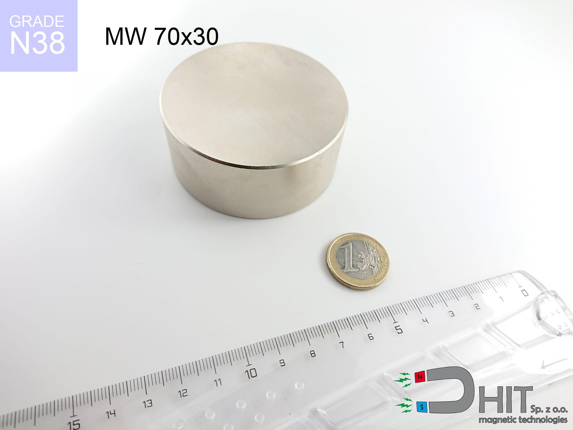
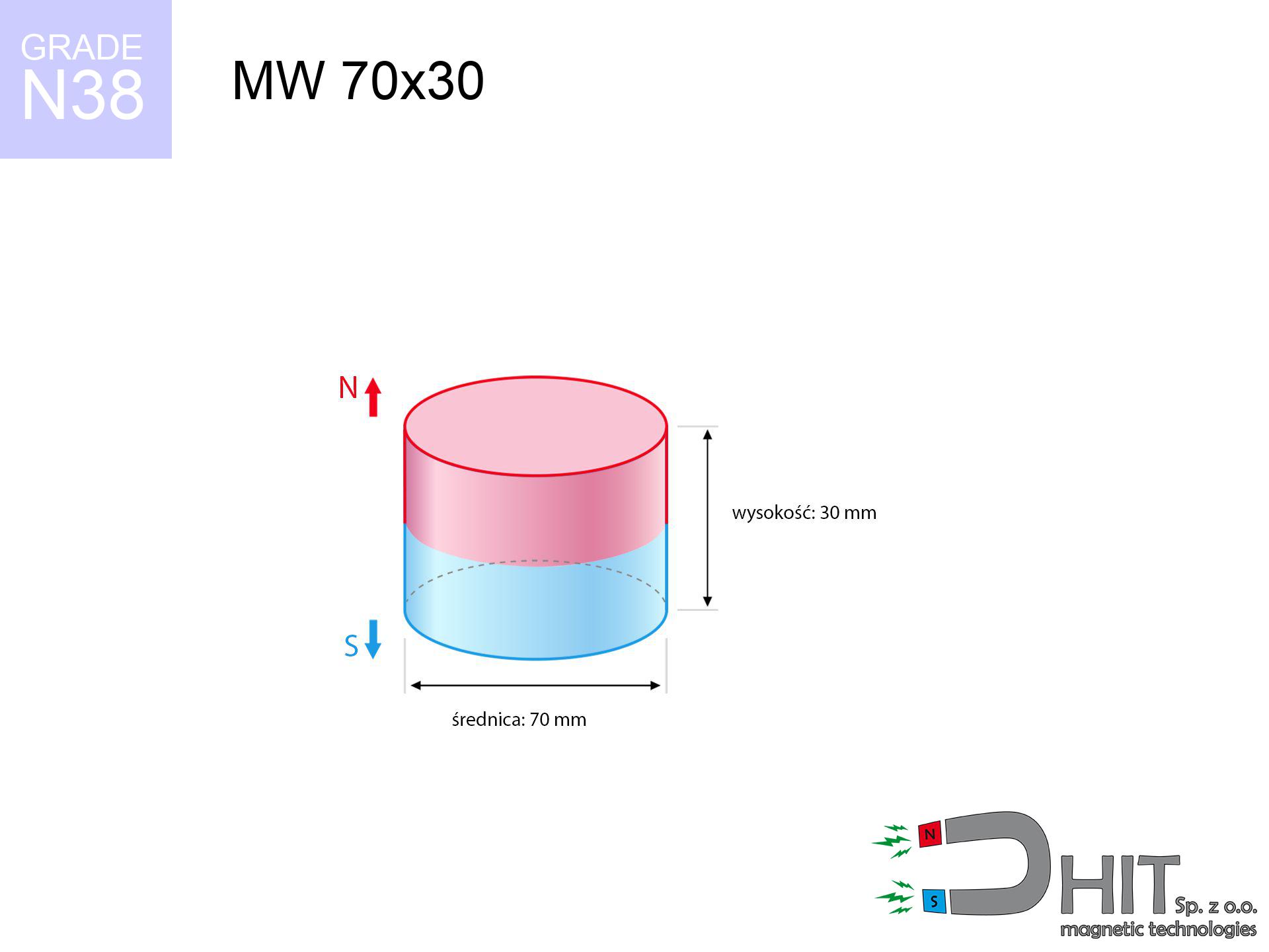
MW 70x30 / N38 - cylindrical magnet
cylindrical magnet
Catalog no 010096
GTIN/EAN: 5906301810957
- Diameter Ø
- 70 mm [±0,1 mm]
- Height
- 30 mm [±0,1 mm]
- Weight
- 865.9 g
- Magnetization Direction
- ↑ axial
- Coating
- [NiCuNi] Nickel
How we measure these parameters — certificates and measurements
257.86 zł net / pcs
317.17 zł with VAT (23% VAT) / pcs
bulk discounts:
Need more?Frequently asked questions
Where can I buy strong cylindrical neodymium magnets?
Can a small cylindrical magnet provide a strong grip for precise workshop work?
Which cylindrical magnet can work at a higher temperature?
Engineering report for this magnet
Full PDF analysis: pull and shear force, effect of distance, temperature and plate thickness, safety distances and the demagnetization curve.
Call us now
+48 888 99 98 98
alternatively let us know using
contact form
the contact section.
Specifications and structure of a neodymium magnet can be estimated using our
power calculator.
Order by 14:00 and we’ll ship today!
Technical parameters - MW 70x30 / N38 - cylindrical magnet
Specification / characteristics - MW 70x30 / N38 - cylindrical magnet
| properties | values |
|---|---|
| Cat. no. | 010096 |
| GTIN/EAN | 5906301810957 |
| Production/Distribution | Dhit sp. z o.o. |
| Country of origin | Poland / China / Germany |
| Customs code | 85059029 |
| Diameter Ø | 70 mm [±0,1 mm] |
| Height | 30 mm [±0,1 mm] |
| Weight | 865.9 g |
| Magnetization Direction | ↑ axial |
| Load capacity ~ ? | 144.18 kg / 1414.37 N |
| Magnetic Induction ~ ? | 403.43 mT / 4034 Gs |
| Coating | [NiCuNi] Nickel |
| Manufacturing Tolerance | ±0.1 mm |
Magnetic properties of material N38
| properties | values | units |
|---|---|---|
| Remanence Br ? | 12.2-12.6 | kGs |
| Remanence Br ? | 1220-1260 | mT |
| Coercivity bHc ? | 10.8-11.5 | kOe |
| Coercivity bHc ? | 860-915 | kA/m |
| Intrinsic coercivity iHc | ≥ 12 | kOe |
| Intrinsic coercivity iHc | ≥ 955 | kA/m |
| Energy product BHmax ? | 36-38 | BH max MGOe |
| Energy product BHmax ? | 287-303 | BH max KJ/m |
| Maximum working temperature ? | ≤ 80 | °C |
Physical properties of sintered neodymium magnets Nd2Fe14B at 20°C
| properties | values | units |
|---|---|---|
| Vickers hardness | ≥550 | Hv |
| Density | ≥7.4 | g/cm3 |
| Curie Temperature TC | 310 | °C |
| Curie Temperature TF | 590 | °F |
| Specific resistance | 150 | μΩ⋅cm |
| Bending strength | 250 | MPa |
| Compressive strength | 1000~1100 | MPa |
| Thermal expansion parallel (∥) to orientation (M) | (3-4) x 10-6 | °C-1 |
| Thermal expansion perpendicular (⊥) to orientation (M) | -(1-3) x 10-6 | °C-1 |
| Young's modulus | 1.7 x 10⁴ | kg/mm² |
Physical modeling of the magnet - data
Presented information are the result of a physical calculation. Results rely on algorithms for the material Nd2Fe14B. Real-world conditions might slightly deviate from the simulation results. Treat these calculations as a reference point when designing systems.
Table 1: Static pull force (pull vs distance) - power drop
MW 70x30 / N38
| Distance (mm) | Induction (Gauss) / mT | Pull Force (kg/lbs/g/N) | Risk Status |
|---|---|---|---|
| 0 mm |
4034 Gs
403.4 mT
|
144.18 kg / 317.86 lbs
144180.0 g / 1414.4 N
|
crushing |
| 1 mm |
3934 Gs
393.4 mT
|
137.11 kg / 302.27 lbs
137108.9 g / 1345.0 N
|
crushing |
| 2 mm |
3830 Gs
383.0 mT
|
129.96 kg / 286.52 lbs
129962.6 g / 1274.9 N
|
crushing |
| 3 mm |
3724 Gs
372.4 mT
|
122.86 kg / 270.87 lbs
122863.7 g / 1205.3 N
|
crushing |
| 5 mm |
3507 Gs
350.7 mT
|
108.99 kg / 240.28 lbs
108989.8 g / 1069.2 N
|
crushing |
| 10 mm |
2963 Gs
296.3 mT
|
77.77 kg / 171.46 lbs
77773.1 g / 763.0 N
|
crushing |
| 15 mm |
2452 Gs
245.2 mT
|
53.26 kg / 117.41 lbs
53257.6 g / 522.5 N
|
crushing |
| 20 mm |
2003 Gs
200.3 mT
|
35.55 kg / 78.38 lbs
35554.2 g / 348.8 N
|
crushing |
| 30 mm |
1321 Gs
132.1 mT
|
15.45 kg / 34.06 lbs
15450.6 g / 151.6 N
|
crushing |
| 50 mm |
601 Gs
60.1 mT
|
3.20 kg / 7.05 lbs
3199.7 g / 31.4 N
|
strong |
Table 2: Slippage capacity (vertical surface)
MW 70x30 / N38
| Distance (mm) | Friction coefficient | Pull Force (kg/lbs/g/N) |
|---|---|---|
| 0 mm | Stal (~0.2) |
28.84 kg / 63.57 lbs
28836.0 g / 282.9 N
|
| 1 mm | Stal (~0.2) |
27.42 kg / 60.46 lbs
27422.0 g / 269.0 N
|
| 2 mm | Stal (~0.2) |
25.99 kg / 57.30 lbs
25992.0 g / 255.0 N
|
| 3 mm | Stal (~0.2) |
24.57 kg / 54.17 lbs
24572.0 g / 241.1 N
|
| 5 mm | Stal (~0.2) |
21.80 kg / 48.06 lbs
21798.0 g / 213.8 N
|
| 10 mm | Stal (~0.2) |
15.55 kg / 34.29 lbs
15554.0 g / 152.6 N
|
| 15 mm | Stal (~0.2) |
10.65 kg / 23.48 lbs
10652.0 g / 104.5 N
|
| 20 mm | Stal (~0.2) |
7.11 kg / 15.67 lbs
7110.0 g / 69.7 N
|
| 30 mm | Stal (~0.2) |
3.09 kg / 6.81 lbs
3090.0 g / 30.3 N
|
| 50 mm | Stal (~0.2) |
0.64 kg / 1.41 lbs
640.0 g / 6.3 N
|
Table 3: Wall mounting (sliding) - vertical pull
MW 70x30 / N38
| Surface type | Friction coefficient / % Mocy | Max load (kg/lbs/g/N) |
|---|---|---|
| Raw steel |
µ = 0.3
30% Nominalnej Siły
|
43.25 kg / 95.36 lbs
43254.0 g / 424.3 N
|
| Painted steel (standard) |
µ = 0.2
20% Nominalnej Siły
|
28.84 kg / 63.57 lbs
28836.0 g / 282.9 N
|
| Oily/slippery steel |
µ = 0.1
10% Nominalnej Siły
|
14.42 kg / 31.79 lbs
14418.0 g / 141.4 N
|
| Magnet with anti-slip rubber |
µ = 0.5
50% Nominalnej Siły
|
72.09 kg / 158.93 lbs
72090.0 g / 707.2 N
|
Table 4: Steel thickness (saturation) - sheet metal selection
MW 70x30 / N38
| Steel thickness (mm) | % power | Real pull force (kg/lbs/g/N) |
|---|---|---|
| 0.5 mm |
|
4.81 kg / 10.60 lbs
4806.0 g / 47.1 N
|
| 1 mm |
|
12.01 kg / 26.49 lbs
12015.0 g / 117.9 N
|
| 2 mm |
|
24.03 kg / 52.98 lbs
24030.0 g / 235.7 N
|
| 3 mm |
|
36.05 kg / 79.47 lbs
36045.0 g / 353.6 N
|
| 5 mm |
|
60.08 kg / 132.44 lbs
60075.0 g / 589.3 N
|
| 10 mm |
|
120.15 kg / 264.89 lbs
120150.0 g / 1178.7 N
|
| 11 mm |
|
132.17 kg / 291.37 lbs
132165.0 g / 1296.5 N
|
| 12 mm |
|
144.18 kg / 317.86 lbs
144180.0 g / 1414.4 N
|
Table 5: Working in heat (stability) - resistance threshold
MW 70x30 / N38
| Ambient temp. (°C) | Power loss | Remaining pull (kg/lbs/g/N) | Status |
|---|---|---|---|
| 20 °C | 0.0% |
144.18 kg / 317.86 lbs
144180.0 g / 1414.4 N
|
OK |
| 40 °C | -2.2% |
141.01 kg / 310.87 lbs
141008.0 g / 1383.3 N
|
OK |
| 60 °C | -4.4% |
137.84 kg / 303.88 lbs
137836.1 g / 1352.2 N
|
|
| 80 °C | -6.6% |
134.66 kg / 296.88 lbs
134664.1 g / 1321.1 N
|
|
| 100 °C | -28.8% |
102.66 kg / 226.32 lbs
102656.2 g / 1007.1 N
|
Table 6: Two magnets (repulsion) - field range
MW 70x30 / N38
| Gap (mm) | Attraction (kg/lbs) (N-S) | Shear Strength (kg/lbs/g/N) | Repulsion (kg/lbs) (N-N) |
|---|---|---|---|
| 0 mm |
386.08 kg / 851.15 lbs
5 354 Gs
|
57.91 kg / 127.67 lbs
57911 g / 568.1 N
|
N/A |
| 1 mm |
376.71 kg / 830.51 lbs
7 969 Gs
|
56.51 kg / 124.58 lbs
56507 g / 554.3 N
|
339.04 kg / 747.46 lbs
~0 Gs
|
| 2 mm |
367.14 kg / 809.41 lbs
7 867 Gs
|
55.07 kg / 121.41 lbs
55071 g / 540.2 N
|
330.43 kg / 728.47 lbs
~0 Gs
|
| 3 mm |
357.57 kg / 788.30 lbs
7 764 Gs
|
53.63 kg / 118.24 lbs
53635 g / 526.2 N
|
321.81 kg / 709.47 lbs
~0 Gs
|
| 5 mm |
338.48 kg / 746.21 lbs
7 554 Gs
|
50.77 kg / 111.93 lbs
50772 g / 498.1 N
|
304.63 kg / 671.59 lbs
~0 Gs
|
| 10 mm |
291.85 kg / 643.41 lbs
7 014 Gs
|
43.78 kg / 96.51 lbs
43777 g / 429.5 N
|
262.66 kg / 579.07 lbs
~0 Gs
|
| 20 mm |
208.26 kg / 459.13 lbs
5 925 Gs
|
31.24 kg / 68.87 lbs
31238 g / 306.4 N
|
187.43 kg / 413.21 lbs
~0 Gs
|
| 50 mm |
62.81 kg / 138.47 lbs
3 254 Gs
|
9.42 kg / 20.77 lbs
9421 g / 92.4 N
|
56.53 kg / 124.62 lbs
~0 Gs
|
| 60 mm |
41.37 kg / 91.21 lbs
2 641 Gs
|
6.21 kg / 13.68 lbs
6206 g / 60.9 N
|
37.24 kg / 82.09 lbs
~0 Gs
|
| 70 mm |
27.41 kg / 60.43 lbs
2 150 Gs
|
4.11 kg / 9.06 lbs
4112 g / 40.3 N
|
24.67 kg / 54.39 lbs
~0 Gs
|
| 80 mm |
18.35 kg / 40.46 lbs
1 759 Gs
|
2.75 kg / 6.07 lbs
2753 g / 27.0 N
|
16.52 kg / 36.41 lbs
~0 Gs
|
| 90 mm |
12.45 kg / 27.44 lbs
1 449 Gs
|
1.87 kg / 4.12 lbs
1867 g / 18.3 N
|
11.20 kg / 24.70 lbs
~0 Gs
|
| 100 mm |
8.57 kg / 18.89 lbs
1 202 Gs
|
1.29 kg / 2.83 lbs
1285 g / 12.6 N
|
7.71 kg / 17.00 lbs
~0 Gs
|
Table 7: Safety (HSE) (electronics) - warnings
MW 70x30 / N38
| Object / Device | Limit (Gauss) / mT | Safe distance |
|---|---|---|
| Pacemaker | 5 Gs (0.5 mT) | 34.5 cm |
| Hearing aid | 10 Gs (1.0 mT) | 27.0 cm |
| Timepiece | 20 Gs (2.0 mT) | 21.0 cm |
| Phone / Smartphone | 40 Gs (4.0 mT) | 16.5 cm |
| Remote | 50 Gs (5.0 mT) | 15.0 cm |
| Payment card | 400 Gs (40.0 mT) | 6.5 cm |
| HDD hard drive | 600 Gs (60.0 mT) | 5.5 cm |
Table 8: Dynamics (cracking risk) - collision effects
MW 70x30 / N38
| Start from (mm) | Speed (km/h) | Energy (J) | Predicted outcome |
|---|---|---|---|
| 10 mm |
17.95 km/h
(4.99 m/s)
|
10.76 J | |
| 30 mm |
23.51 km/h
(6.53 m/s)
|
18.46 J | |
| 50 mm |
24.45 km/h
(6.79 m/s)
|
19.97 J | |
| 100 mm |
24.72 km/h
(6.87 m/s)
|
20.42 J |
Table 9: Anti-corrosion coating durability
MW 70x30 / N38
| Technical parameter | Value / Description |
|---|---|
| Coating type | [NiCuNi] Nickel |
| Layer structure | Nickel - Copper - Nickel |
| Layer thickness | 10-20 µm |
| Salt spray test (SST) ? | 24 h |
| Recommended environment | Indoors only (dry) |
Table 10: Construction data (Pc)
MW 70x30 / N38
| Parameter | Value | SI Unit / Description |
|---|---|---|
| Magnetic Flux | 159 225 Mx | 1592.3 µWb |
| Pc Coefficient | 0.53 | Low (Flat) |
Table 11: Physics of underwater searching
MW 70x30 / N38
| Environment | Effective steel pull | Effect |
|---|---|---|
| Air (land) | 144.18 kg | Standard |
| Water (riverbed) |
165.09 kg
(+20.91 kg buoyancy gain)
|
+14.5% |
1. Vertical hold
*Warning: On a vertical surface, the magnet retains merely approx. 20-30% of its perpendicular strength.
2. Efficiency vs thickness
*Thin steel (e.g. 0.5mm PC case) drastically weakens the holding force.
3. Thermal stability
N38: the maximum material working temperature is 80°C. Permitted conditions also depend on the shape and magnetic circuit.
4. Demagnetization curve and operating point (B-H)
chart generated for the permeance coefficient Pc (Permeance Coefficient) = 0.53
The chart above illustrates the magnetic characteristics of the material within the second quadrant of the hysteresis loop. The solid red line represents the demagnetization curve (material potential), while the dashed blue line is the load line based on the magnet's geometry. The Pc (Permeance Coefficient), also known as the load line slope, is a dimensionless value that describes the relationship between the magnet's shape and its magnetic stability. The intersection of these two lines (the black dot) is the operating point — it determines the actual magnetic flux density generated by the magnet in this specific configuration. A higher Pc value means the magnet is more 'slender' (tall relative to its area), resulting in a higher operating point and better resistance to irreversible demagnetization caused by external fields or temperature. A value of 0.42 is relatively low (typical for flat magnets), meaning the operating point is closer to the 'knee' of the curve — caution is advised when operating at temperatures near the maximum limit to avoid strength loss.
Elemental analysis
| iron (Fe) | 64% – 68% |
| neodymium (Nd) | 29% – 32% |
| boron (B) | 1.1% – 1.2% |
| dysprosium (Dy) | 0.5% – 2.0% |
| coating (Ni-Cu-Ni) | < 0.05% |
Environmental data
| recyclability (EoL) | 100% |
| recycled raw materials | ~10% (pre-cons) |
| carbon footprint | low / zredukowany |
| waste code (EWC) | 16 02 16 |
Check out more deals

Pros and cons of rare earth magnets.
Benefits
- They do not lose strength, even during around ten years – the reduction in strength is only ~1% (theoretically),
- They are resistant to demagnetization induced by external disturbances,
- A magnet with a shiny silver surface has better aesthetics,
- Neodymium magnets ensure maximum magnetic induction on a their surface, which allows for strong attraction,
- Due to their durability and thermal resistance, neodymium magnets can operate (depending on the form) even at high temperatures reaching 230°C or more...
- Possibility of exact modeling as well as optimizing to defined needs,
- Universal use in advanced technology sectors – they find application in data components, brushless drives, diagnostic systems, and industrial machines.
- Compactness – despite small sizes they generate large force, making them ideal for precision applications
Limitations
- At very strong impacts they can break, therefore we recommend placing them in strong housings. A metal housing provides additional protection against damage and increases the magnet's durability.
- Do not exceed this material temperature limit: 80°C. Overheating may permanently weaken the magnet.
- Due to the susceptibility of magnets to corrosion in a humid environment, we recommend using waterproof magnets made of rubber, plastic or other material stable to moisture, in case of application outdoors
- Limited possibility of creating threads in the magnet and complex shapes - recommended is a housing - mounting mechanism.
- Health risk resulting from small fragments of magnets pose a threat, in case of ingestion, which gains importance in the context of child safety. Furthermore, tiny parts of these magnets can complicate diagnosis medical in case of swallowing.
- Due to neodymium price, their price is relatively high,
Holding force characteristics
Maximum lifting capacity of the magnet – what it depends on?
- on a plate made of mild steel, optimally conducting the magnetic flux
- with a cross-section no less than 10 mm
- characterized by lack of roughness
- without any air gap between the magnet and steel
- during pulling in a direction perpendicular to the mounting surface
- in neutral thermal conditions
Determinants of lifting force in real conditions
- Distance (between the magnet and the plate), as even a very small clearance (e.g. 0.5 mm) leads to a decrease in force by up to 50% (this also applies to varnish, corrosion or dirt).
- Force direction – declared lifting capacity refers to detachment vertically. When applying parallel force, the magnet exhibits much less (often approx. 20-30% of maximum force).
- Plate thickness – too thin sheet does not accept the full field, causing part of the flux to be escaped to the other side.
- Plate material – mild steel gives the best results. Alloy admixtures reduce magnetic properties and holding force.
- Plate texture – smooth surfaces ensure maximum contact, which increases force. Uneven metal reduce efficiency.
- Thermal environment – temperature increase results in weakening of induction. It is worth remembering the maximum operating temperature for a given model.
Lifting capacity testing was performed on plates with a smooth surface of suitable thickness, under perpendicular forces, whereas under attempts to slide the magnet the lifting capacity is smaller. Moreover, even a small distance between the magnet’s surface and the plate decreases the lifting capacity.
Precautions when working with NdFeB magnets
Threat to electronics
Do not bring magnets near a purse, laptop, or screen. The magnetism can irreversibly ruin these devices and wipe information from cards.
Safe operation
Exercise caution. Neodymium magnets act from a long distance and connect with massive power, often quicker than you can move away.
Flammability
Fire warning: Neodymium dust is highly flammable. Do not process magnets without safety gear as this risks ignition.
Metal Allergy
It is widely known that the nickel plating (standard magnet coating) is a common allergen. For allergy sufferers, prevent touching magnets with bare hands or choose encased magnets.
No play value
Adult use only. Small elements can be swallowed, leading to severe trauma. Keep out of reach of kids and pets.
Threat to navigation
Navigation devices and smartphones are extremely susceptible to magnetic fields. Direct contact with a powerful NdFeB magnet can ruin the internal compass in your phone.
Eye protection
Protect your eyes. Magnets can fracture upon violent connection, launching shards into the air. We recommend safety glasses.
Do not overheat magnets
Regular neodymium magnets (grade N) lose power when the temperature goes above 80°C. Damage is permanent.
Implant safety
Warning for patients: Strong magnetic fields affect medical devices. Maintain at least 30 cm distance or request help to work with the magnets.
Pinching danger
Mind your fingers. Two powerful magnets will join immediately with a force of several hundred kilograms, crushing anything in their path. Be careful!
Tabela kosztu i czasu dostawy
Płatność przed wysyłką:

GLS kurier
Przesyłka będzie u Ciebie za 2-3 dni
14.99 ZŁ

InPost Paczkomaty 24/7
Przesyłka będzie u Ciebie za 1-2 dni
12.30 ZŁ
Płatność przy odbiorze (pobranie):
GLS kurier
Przesyłka będzie u Ciebie za 1-2 dni
23.00 ZŁ