


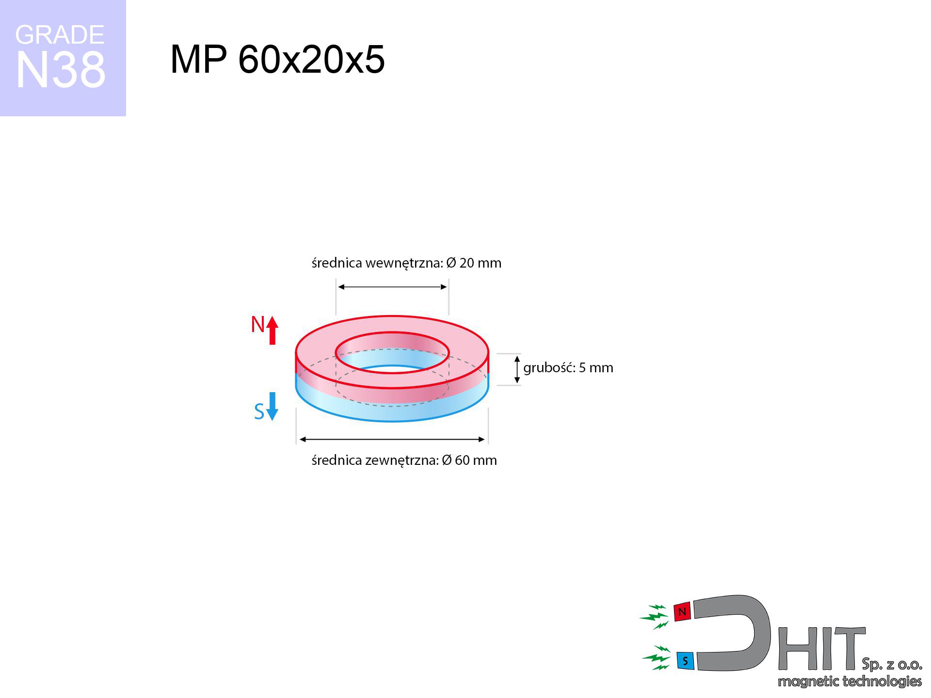
MP 60x20x5 / N38 - ring magnet
ring magnet
Catalog no 030204
GTIN/EAN: 5906301812210
- Diameter
- 60 mm [±0,1 mm]
- internal diameter Ø
- 20 mm [±0,1 mm]
- Height
- 5 mm [±0,1 mm]
- Weight
- 94.25 g
- Magnetization Direction
- ↑ axial
- Coating
- [NiCuNi] Nickel
How we measure these parameters — certificates and measurements
39.02 zł net / pcs
47.99 zł with VAT (23% VAT) / pcs
bulk discounts:
Need more?Frequently asked questions
Where can I compare prices of ring magnets for mounting in Poland?
Are ring magnets resistant to damage?
Which ring magnet is suitable for an outdoor structure?
Where can I check the available sizes of neodymium ring magnets?
Engineering report for this magnet
Full PDF analysis: pull and shear force, effect of distance, temperature and plate thickness, safety distances and the demagnetization curve.
Call us now
+48 888 99 98 98
alternatively let us know using
contact form
the contact section.
Specifications and structure of a neodymium magnet can be estimated using our
power calculator.
Order by 14:00 and we’ll ship today!
Detailed specification - MP 60x20x5 / N38 - ring magnet
Specification / characteristics - MP 60x20x5 / N38 - ring magnet
| properties | values |
|---|---|
| Cat. no. | 030204 |
| GTIN/EAN | 5906301812210 |
| Production/Distribution | Dhit sp. z o.o. |
| Country of origin | Poland / China / Germany |
| Customs code | 85059029 |
| Diameter | 60 mm [±0,1 mm] |
| internal diameter Ø | 20 mm [±0,1 mm] |
| Height | 5 mm [±0,1 mm] |
| Weight | 94.25 g |
| Magnetization Direction | ↑ axial |
| Load capacity ~ ? | 9.41 kg / 92.27 N |
| Magnetic Induction ~ ? | 101.92 mT / 1019 Gs |
| Coating | [NiCuNi] Nickel |
| Manufacturing Tolerance | ±0.1 mm |
Magnetic properties of material N38
| properties | values | units |
|---|---|---|
| Remanence Br ? | 12.2-12.6 | kGs |
| Remanence Br ? | 1220-1260 | mT |
| Coercivity bHc ? | 10.8-11.5 | kOe |
| Coercivity bHc ? | 860-915 | kA/m |
| Intrinsic coercivity iHc | ≥ 12 | kOe |
| Intrinsic coercivity iHc | ≥ 955 | kA/m |
| Energy product BHmax ? | 36-38 | BH max MGOe |
| Energy product BHmax ? | 287-303 | BH max KJ/m |
| Maximum working temperature ? | ≤ 80 | °C |
Physical properties of sintered neodymium magnets Nd2Fe14B at 20°C
| properties | values | units |
|---|---|---|
| Vickers hardness | ≥550 | Hv |
| Density | ≥7.4 | g/cm3 |
| Curie Temperature TC | 310 | °C |
| Curie Temperature TF | 590 | °F |
| Specific resistance | 150 | μΩ⋅cm |
| Bending strength | 250 | MPa |
| Compressive strength | 1000~1100 | MPa |
| Thermal expansion parallel (∥) to orientation (M) | (3-4) x 10-6 | °C-1 |
| Thermal expansion perpendicular (⊥) to orientation (M) | -(1-3) x 10-6 | °C-1 |
| Young's modulus | 1.7 x 10⁴ | kg/mm² |
Physical modeling of the assembly - technical parameters
The following values constitute the result of a mathematical analysis. Values were calculated on algorithms for the material Nd2Fe14B. Actual conditions might slightly differ from theoretical values. Use these calculations as a reference point when designing systems.
Table 1: Static force (pull vs gap) - power drop
MP 60x20x5 / N38
| Distance (mm) | Induction (Gauss) / mT | Pull Force (kg/lbs/g/N) | Risk Status |
|---|---|---|---|
| 0 mm |
4541 Gs
454.1 mT
|
9.41 kg / 20.75 LBS
9410.0 g / 92.3 N
|
strong |
| 1 mm |
4400 Gs
440.0 mT
|
8.83 kg / 19.47 LBS
8832.4 g / 86.6 N
|
strong |
| 2 mm |
4254 Gs
425.4 mT
|
8.26 kg / 18.21 LBS
8258.2 g / 81.0 N
|
strong |
| 3 mm |
4107 Gs
410.7 mT
|
7.70 kg / 16.97 LBS
7697.5 g / 75.5 N
|
strong |
| 5 mm |
3812 Gs
381.2 mT
|
6.63 kg / 14.62 LBS
6630.0 g / 65.0 N
|
strong |
| 10 mm |
3097 Gs
309.7 mT
|
4.38 kg / 9.65 LBS
4375.1 g / 42.9 N
|
strong |
| 15 mm |
2463 Gs
246.3 mT
|
2.77 kg / 6.10 LBS
2767.8 g / 27.2 N
|
strong |
| 20 mm |
1939 Gs
193.9 mT
|
1.72 kg / 3.78 LBS
1715.2 g / 16.8 N
|
safe |
| 30 mm |
1202 Gs
120.2 mT
|
0.66 kg / 1.45 LBS
659.2 g / 6.5 N
|
safe |
| 50 mm |
509 Gs
50.9 mT
|
0.12 kg / 0.26 LBS
118.0 g / 1.2 N
|
safe |
Table 2: Sliding capacity (vertical surface)
MP 60x20x5 / N38
| Distance (mm) | Friction coefficient | Pull Force (kg/lbs/g/N) |
|---|---|---|
| 0 mm | Stal (~0.2) |
1.88 kg / 4.15 LBS
1882.0 g / 18.5 N
|
| 1 mm | Stal (~0.2) |
1.77 kg / 3.89 LBS
1766.0 g / 17.3 N
|
| 2 mm | Stal (~0.2) |
1.65 kg / 3.64 LBS
1652.0 g / 16.2 N
|
| 3 mm | Stal (~0.2) |
1.54 kg / 3.40 LBS
1540.0 g / 15.1 N
|
| 5 mm | Stal (~0.2) |
1.33 kg / 2.92 LBS
1326.0 g / 13.0 N
|
| 10 mm | Stal (~0.2) |
0.88 kg / 1.93 LBS
876.0 g / 8.6 N
|
| 15 mm | Stal (~0.2) |
0.55 kg / 1.22 LBS
554.0 g / 5.4 N
|
| 20 mm | Stal (~0.2) |
0.34 kg / 0.76 LBS
344.0 g / 3.4 N
|
| 30 mm | Stal (~0.2) |
0.13 kg / 0.29 LBS
132.0 g / 1.3 N
|
| 50 mm | Stal (~0.2) |
0.02 kg / 0.05 LBS
24.0 g / 0.2 N
|
Table 3: Vertical assembly (shearing) - behavior on slippery surfaces
MP 60x20x5 / N38
| Surface type | Friction coefficient / % Mocy | Max load (kg/lbs/g/N) |
|---|---|---|
| Raw steel |
µ = 0.3
30% Nominalnej Siły
|
2.82 kg / 6.22 LBS
2823.0 g / 27.7 N
|
| Painted steel (standard) |
µ = 0.2
20% Nominalnej Siły
|
1.88 kg / 4.15 LBS
1882.0 g / 18.5 N
|
| Oily/slippery steel |
µ = 0.1
10% Nominalnej Siły
|
0.94 kg / 2.07 LBS
941.0 g / 9.2 N
|
| Magnet with anti-slip rubber |
µ = 0.5
50% Nominalnej Siły
|
4.71 kg / 10.37 LBS
4705.0 g / 46.2 N
|
Table 4: Material efficiency (saturation) - sheet metal selection
MP 60x20x5 / N38
| Steel thickness (mm) | % power | Real pull force (kg/lbs/g/N) |
|---|---|---|
| 0.5 mm |
|
0.94 kg / 2.07 LBS
941.0 g / 9.2 N
|
| 1 mm |
|
2.35 kg / 5.19 LBS
2352.5 g / 23.1 N
|
| 2 mm |
|
4.71 kg / 10.37 LBS
4705.0 g / 46.2 N
|
| 3 mm |
|
7.06 kg / 15.56 LBS
7057.5 g / 69.2 N
|
| 5 mm |
|
9.41 kg / 20.75 LBS
9410.0 g / 92.3 N
|
| 10 mm |
|
9.41 kg / 20.75 LBS
9410.0 g / 92.3 N
|
| 11 mm |
|
9.41 kg / 20.75 LBS
9410.0 g / 92.3 N
|
| 12 mm |
|
9.41 kg / 20.75 LBS
9410.0 g / 92.3 N
|
Table 5: Thermal stability (stability) - power drop
MP 60x20x5 / N38
| Ambient temp. (°C) | Power loss | Remaining pull (kg/lbs/g/N) | Status |
|---|---|---|---|
| 20 °C | 0.0% |
9.41 kg / 20.75 LBS
9410.0 g / 92.3 N
|
OK |
| 40 °C | -2.2% |
9.20 kg / 20.29 LBS
9203.0 g / 90.3 N
|
OK |
| 60 °C | -4.4% |
9.00 kg / 19.83 LBS
8996.0 g / 88.3 N
|
OK |
| 80 °C | -6.6% |
8.79 kg / 19.38 LBS
8788.9 g / 86.2 N
|
|
| 100 °C | -28.8% |
6.70 kg / 14.77 LBS
6699.9 g / 65.7 N
|
Table 6: Two magnets (repulsion) - field collision
MP 60x20x5 / N38
| Gap (mm) | Attraction (kg/lbs) (N-S) | Shear Strength (kg/lbs/g/N) | Repulsion (kg/lbs) (N-N) |
|---|---|---|---|
| 0 mm |
303.46 kg / 669.01 LBS
5 621 Gs
|
45.52 kg / 100.35 LBS
45519 g / 446.5 N
|
N/A |
| 1 mm |
294.21 kg / 648.62 LBS
8 943 Gs
|
44.13 kg / 97.29 LBS
44132 g / 432.9 N
|
264.79 kg / 583.76 LBS
~0 Gs
|
| 2 mm |
284.83 kg / 627.94 LBS
8 800 Gs
|
42.72 kg / 94.19 LBS
42725 g / 419.1 N
|
256.35 kg / 565.15 LBS
~0 Gs
|
| 3 mm |
275.53 kg / 607.43 LBS
8 655 Gs
|
41.33 kg / 91.11 LBS
41329 g / 405.4 N
|
247.97 kg / 546.69 LBS
~0 Gs
|
| 5 mm |
257.21 kg / 567.06 LBS
8 362 Gs
|
38.58 kg / 85.06 LBS
38582 g / 378.5 N
|
231.49 kg / 510.35 LBS
~0 Gs
|
| 10 mm |
213.81 kg / 471.36 LBS
7 624 Gs
|
32.07 kg / 70.70 LBS
32071 g / 314.6 N
|
192.43 kg / 424.23 LBS
~0 Gs
|
| 20 mm |
141.09 kg / 311.05 LBS
6 193 Gs
|
21.16 kg / 46.66 LBS
21164 g / 207.6 N
|
126.98 kg / 279.95 LBS
~0 Gs
|
| 50 mm |
34.15 kg / 75.30 LBS
3 047 Gs
|
5.12 kg / 11.29 LBS
5123 g / 50.3 N
|
30.74 kg / 67.77 LBS
~0 Gs
|
| 60 mm |
21.26 kg / 46.87 LBS
2 404 Gs
|
3.19 kg / 7.03 LBS
3189 g / 31.3 N
|
19.13 kg / 42.18 LBS
~0 Gs
|
| 70 mm |
13.43 kg / 29.61 LBS
1 911 Gs
|
2.01 kg / 4.44 LBS
2015 g / 19.8 N
|
12.09 kg / 26.65 LBS
~0 Gs
|
| 80 mm |
8.65 kg / 19.06 LBS
1 533 Gs
|
1.30 kg / 2.86 LBS
1297 g / 12.7 N
|
7.78 kg / 17.16 LBS
~0 Gs
|
| 90 mm |
5.68 kg / 12.52 LBS
1 243 Gs
|
0.85 kg / 1.88 LBS
852 g / 8.4 N
|
5.11 kg / 11.27 LBS
~0 Gs
|
| 100 mm |
3.81 kg / 8.39 LBS
1 017 Gs
|
0.57 kg / 1.26 LBS
571 g / 5.6 N
|
3.43 kg / 7.55 LBS
~0 Gs
|
Table 7: Protective zones (implants) - precautionary measures
MP 60x20x5 / N38
| Object / Device | Limit (Gauss) / mT | Safe distance |
|---|---|---|
| Pacemaker | 5 Gs (0.5 mT) | 31.5 cm |
| Hearing aid | 10 Gs (1.0 mT) | 24.5 cm |
| Timepiece | 20 Gs (2.0 mT) | 19.5 cm |
| Mobile device | 40 Gs (4.0 mT) | 15.0 cm |
| Remote | 50 Gs (5.0 mT) | 14.0 cm |
| Payment card | 400 Gs (40.0 mT) | 6.0 cm |
| HDD hard drive | 600 Gs (60.0 mT) | 5.0 cm |
Table 8: Dynamics (kinetic energy) - collision effects
MP 60x20x5 / N38
| Start from (mm) | Speed (km/h) | Energy (J) | Predicted outcome |
|---|---|---|---|
| 10 mm |
13.47 km/h
(3.74 m/s)
|
0.66 J | |
| 30 mm |
16.98 km/h
(4.72 m/s)
|
1.05 J | |
| 50 mm |
17.46 km/h
(4.85 m/s)
|
1.11 J | |
| 100 mm |
17.58 km/h
(4.88 m/s)
|
1.12 J |
Table 9: Coating parameters (durability)
MP 60x20x5 / N38
| Technical parameter | Value / Description |
|---|---|
| Coating type | [NiCuNi] Nickel |
| Layer structure | Nickel - Copper - Nickel |
| Layer thickness | 10-20 µm |
| Salt spray test (SST) ? | 24 h |
| Recommended environment | Indoors only (dry) |
Table 10: Construction data (Flux)
MP 60x20x5 / N38
| Parameter | Value | SI Unit / Description |
|---|---|---|
| Magnetic Flux | 109 640 Mx | 1096.4 µWb |
| Pc Coefficient | 0.62 | High (Stable) |
Table 11: Underwater work (magnet fishing)
MP 60x20x5 / N38
| Environment | Effective steel pull | Effect |
|---|---|---|
| Air (land) | 9.41 kg | Standard |
| Water (riverbed) |
10.77 kg
(+1.36 kg buoyancy gain)
|
+14.5% |
1. Vertical hold
*Note: On a vertical wall, the magnet holds just ~20% of its max power.
2. Steel thickness impact
*Thin metal sheet (e.g. computer case) significantly reduces the holding force.
3. Thermal stability
N38: the maximum material working temperature is 80°C. Permitted conditions also depend on the shape and magnetic circuit.
4. Demagnetization curve and operating point (B-H)
chart generated for the permeance coefficient Pc (Permeance Coefficient) = 0.62
This simulation demonstrates the magnetic stability of the selected magnet under specific geometric conditions. The solid red line represents the demagnetization curve (material potential), while the dashed blue line is the load line based on the magnet's geometry. The Pc (Permeance Coefficient), also known as the load line slope, is a dimensionless value that describes the relationship between the magnet's shape and its magnetic stability. The intersection of these two lines (the black dot) is the operating point — it determines the actual magnetic flux density generated by the magnet in this specific configuration. A higher Pc value means the magnet is more 'slender' (tall relative to its area), resulting in a higher operating point and better resistance to irreversible demagnetization caused by external fields or temperature. A value of 0.42 is relatively low (typical for flat magnets), meaning the operating point is closer to the 'knee' of the curve — caution is advised when operating at temperatures near the maximum limit to avoid strength loss.
Elemental analysis
| iron (Fe) | 64% – 68% |
| neodymium (Nd) | 29% – 32% |
| boron (B) | 1.1% – 1.2% |
| dysprosium (Dy) | 0.5% – 2.0% |
| coating (Ni-Cu-Ni) | < 0.05% |
Environmental data
| recyclability (EoL) | 100% |
| recycled raw materials | ~10% (pre-cons) |
| carbon footprint | low / zredukowany |
| waste code (EWC) | 16 02 16 |
Other products
![UMH 25x8x45 [M5] / N38 - magnetic holder with hook](https://cdn3.dhit.pl/graphics/products/umh-25x8x45-m5-cep.jpg "UMH 25x8x45 [M5] / N38 - magnetic holder with hook")

![SM 25x150 [2xM8] / N52 - magnetic separator](https://cdn3.dhit.pl/graphics/products/sm-25x150-2xm8-sux.jpg "SM 25x150 [2xM8] / N52 - magnetic separator")

Pros and cons of Nd2Fe14B magnets.
Advantages
- They have constant strength, and over nearly 10 years their attraction force decreases symbolically – ~1% (in testing),
- They possess excellent resistance to magnetism drop as a result of opposing magnetic fields,
- The use of an metallic layer of noble metals (nickel, gold, silver) causes the element to have aesthetics,
- The surface of neodymium magnets generates a powerful magnetic field – this is a key feature,
- Made from properly selected components, these magnets show impressive resistance to high heat, enabling them to function (depending on their form) at temperatures up to 230°C and above...
- Thanks to versatility in forming and the capacity to adapt to client solutions,
- Huge importance in electronics industry – they find application in mass storage devices, drive modules, precision medical tools, as well as multitasking production systems.
- Thanks to efficiency per cm³, small magnets offer high operating force, occupying minimum space,
Cons
- At very strong impacts they can crack, therefore we recommend placing them in special holders. A metal housing provides additional protection against damage, as well as increases the magnet's durability.
- Do not exceed this material temperature limit: 80°C. Overheating may permanently weaken the magnet.
- When exposed to humidity, magnets start to rust. For applications outside, it is recommended to use protective magnets, such as those in rubber or plastics, which secure oxidation as well as corrosion.
- We suggest casing - magnetic holder, due to difficulties in creating threads inside the magnet and complicated shapes.
- Health risk resulting from small fragments of magnets pose a threat, if swallowed, which is particularly important in the context of child safety. It is also worth noting that small elements of these products can complicate diagnosis medical after entering the body.
- Higher cost of purchase is a significant factor to consider compared to ceramic magnets, especially in budget applications
Lifting parameters
Maximum holding power of the magnet – what affects it?
- on a plate made of structural steel, perfectly concentrating the magnetic field
- whose transverse dimension equals approx. 10 mm
- characterized by smoothness
- without the slightest insulating layer between the magnet and steel
- under vertical force direction (90-degree angle)
- in neutral thermal conditions
Lifting capacity in real conditions – factors
- Distance – existence of any layer (rust, tape, gap) acts as an insulator, which reduces capacity steeply (even by 50% at 0.5 mm).
- Force direction – remember that the magnet holds strongest perpendicularly. Under sliding down, the capacity drops significantly, often to levels of 20-30% of the nominal value.
- Metal thickness – thin material does not allow full use of the magnet. Part of the magnetic field penetrates through instead of converting into lifting capacity.
- Plate material – low-carbon steel gives the best results. Higher carbon content lower magnetic permeability and lifting capacity.
- Smoothness – full contact is obtained only on polished steel. Rough texture create air cushions, weakening the magnet.
- Heat – neodymium magnets have a negative temperature coefficient. At higher temperatures they lose power, and in frost gain strength (up to a certain limit).
Lifting capacity testing was performed on plates with a smooth surface of suitable thickness, under a perpendicular pulling force, however under attempts to slide the magnet the holding force is lower. In addition, even a small distance between the magnet and the plate reduces the lifting capacity.
H&S for magnets
Demagnetization risk
Do not overheat. NdFeB magnets are sensitive to temperature. If you require operation above 80°C, ask us about special high-temperature series (H, SH, UH).
Nickel coating and allergies
Allergy Notice: The Ni-Cu-Ni coating consists of nickel. If redness happens, immediately stop working with magnets and wear gloves.
Do not underestimate power
Before starting, read the rules. Sudden snapping can destroy the magnet or hurt your hand. Think ahead.
Dust is flammable
Fire warning: Rare earth powder is explosive. Avoid machining magnets in home conditions as this may cause fire.
Finger safety
Mind your fingers. Two powerful magnets will join immediately with a force of massive weight, crushing anything in their path. Exercise extreme caution!
Risk of cracking
NdFeB magnets are ceramic materials, meaning they are prone to chipping. Impact of two magnets leads to them breaking into small pieces.
Keep away from electronics
GPS units and smartphones are extremely susceptible to magnetism. Close proximity with a powerful NdFeB magnet can decalibrate the internal compass in your phone.
Medical interference
Life threat: Neodymium magnets can deactivate pacemakers and defibrillators. Stay away if you have electronic implants.
Do not give to children
Absolutely store magnets away from children. Ingestion danger is high, and the effects of magnets connecting inside the body are tragic.
Electronic devices
Very strong magnetic fields can corrupt files on credit cards, hard drives, and storage devices. Stay away of at least 10 cm.
Tabela kosztu i czasu dostawy
Płatność przed wysyłką:

GLS kurier
Przesyłka będzie u Ciebie za 2-3 dni
14.99 ZŁ

InPost Paczkomaty 24/7
Przesyłka będzie u Ciebie za 1-2 dni
12.30 ZŁ
Płatność przy odbiorze (pobranie):
GLS kurier
Przesyłka będzie u Ciebie za 1-2 dni
23.00 ZŁ