

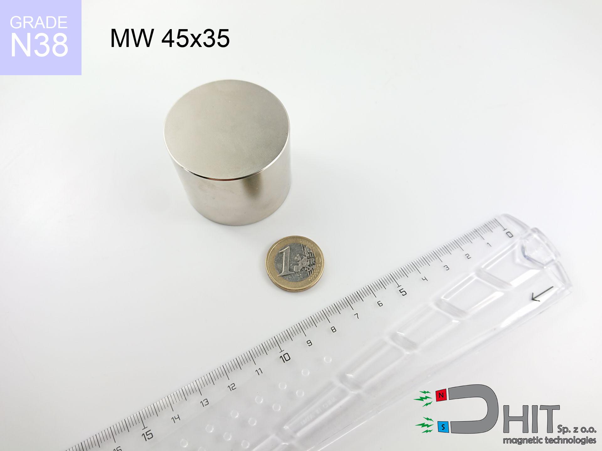
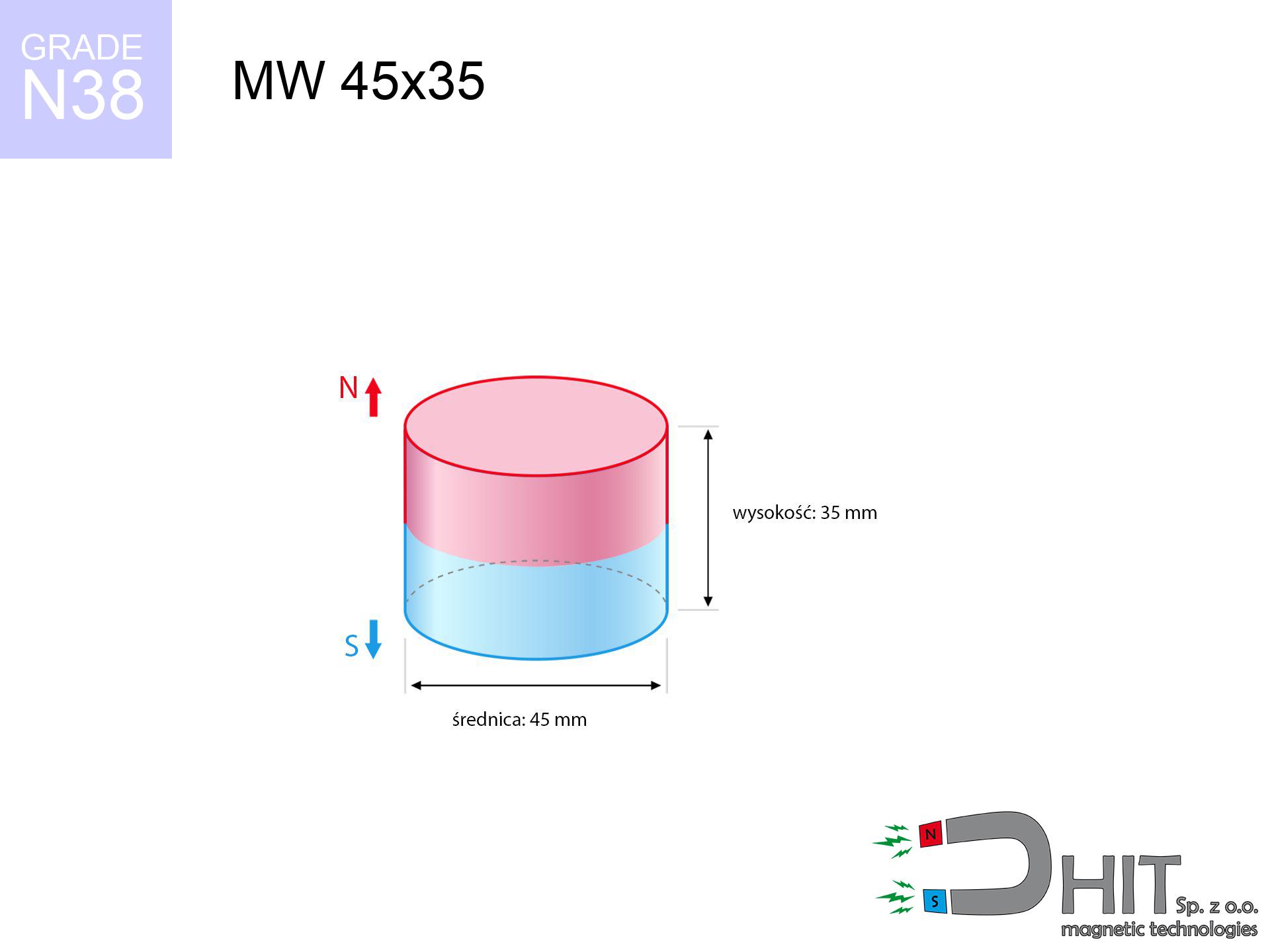
MW 45x35 / N38 - cylindrical magnet
cylindrical magnet
Catalog no 010074
GTIN/EAN: 5906301810735
- Diameter Ø
- 45 mm [±0,1 mm]
- Height
- 35 mm [±0,1 mm]
- Weight
- 417.49 g
- Magnetization Direction
- ↑ axial
- Coating
- [NiCuNi] Nickel
How we measure these parameters — certificates and measurements
146.42 zł net / pcs
180.10 zł with VAT (23% VAT) / pcs
bulk discounts:
Need more?Frequently asked questions
Where can I buy strong cylindrical neodymium magnets?
Can a small cylindrical magnet provide a strong grip for precise workshop work?
Which cylindrical magnet can work at a higher temperature?
Engineering report for this magnet
Full PDF analysis: pull and shear force, effect of distance, temperature and plate thickness, safety distances and the demagnetization curve.
Call us now
+48 888 99 98 98
alternatively let us know using
contact form
the contact section.
Specifications and structure of a neodymium magnet can be estimated using our
power calculator.
Order by 14:00 and we’ll ship today!
Technical parameters - MW 45x35 / N38 - cylindrical magnet
Specification / characteristics - MW 45x35 / N38 - cylindrical magnet
| properties | values |
|---|---|
| Cat. no. | 010074 |
| GTIN/EAN | 5906301810735 |
| Production/Distribution | Dhit sp. z o.o. |
| Country of origin | Poland / China / Germany |
| Customs code | 85059029 |
| Diameter Ø | 45 mm [±0,1 mm] |
| Height | 35 mm [±0,1 mm] |
| Weight | 417.49 g |
| Magnetization Direction | ↑ axial |
| Load capacity ~ ? | 68.98 kg / 676.73 N |
| Magnetic Induction ~ ? | 521.39 mT / 5214 Gs |
| Coating | [NiCuNi] Nickel |
| Manufacturing Tolerance | ±0.1 mm |
Magnetic properties of material N38
| properties | values | units |
|---|---|---|
| Remanence Br ? | 12.2-12.6 | kGs |
| Remanence Br ? | 1220-1260 | mT |
| Coercivity bHc ? | 10.8-11.5 | kOe |
| Coercivity bHc ? | 860-915 | kA/m |
| Intrinsic coercivity iHc | ≥ 12 | kOe |
| Intrinsic coercivity iHc | ≥ 955 | kA/m |
| Energy product BHmax ? | 36-38 | BH max MGOe |
| Energy product BHmax ? | 287-303 | BH max KJ/m |
| Maximum working temperature ? | ≤ 80 | °C |
Physical properties of sintered neodymium magnets Nd2Fe14B at 20°C
| properties | values | units |
|---|---|---|
| Vickers hardness | ≥550 | Hv |
| Density | ≥7.4 | g/cm3 |
| Curie Temperature TC | 310 | °C |
| Curie Temperature TF | 590 | °F |
| Specific resistance | 150 | μΩ⋅cm |
| Bending strength | 250 | MPa |
| Compressive strength | 1000~1100 | MPa |
| Thermal expansion parallel (∥) to orientation (M) | (3-4) x 10-6 | °C-1 |
| Thermal expansion perpendicular (⊥) to orientation (M) | -(1-3) x 10-6 | °C-1 |
| Young's modulus | 1.7 x 10⁴ | kg/mm² |
Physical simulation of the assembly - technical parameters
The following data constitute the outcome of a mathematical calculation. Values rely on algorithms for the material Nd2Fe14B. Operational conditions may differ from theoretical values. Please consider these calculations as a supplementary guide when designing systems.
Table 1: Static pull force (force vs gap) - characteristics
MW 45x35 / N38
| Distance (mm) | Induction (Gauss) / mT | Pull Force (kg/lbs/g/N) | Risk Status |
|---|---|---|---|
| 0 mm |
5213 Gs
521.3 mT
|
68.98 kg / 152.07 LBS
68980.0 g / 676.7 N
|
crushing |
| 1 mm |
4982 Gs
498.2 mT
|
63.01 kg / 138.91 LBS
63010.2 g / 618.1 N
|
crushing |
| 2 mm |
4748 Gs
474.8 mT
|
57.23 kg / 126.18 LBS
57234.3 g / 561.5 N
|
crushing |
| 3 mm |
4516 Gs
451.6 mT
|
51.76 kg / 114.10 LBS
51756.9 g / 507.7 N
|
crushing |
| 5 mm |
4059 Gs
405.9 mT
|
41.82 kg / 92.19 LBS
41816.3 g / 410.2 N
|
crushing |
| 10 mm |
3027 Gs
302.7 mT
|
23.26 kg / 51.29 LBS
23264.1 g / 228.2 N
|
crushing |
| 15 mm |
2215 Gs
221.5 mT
|
12.45 kg / 27.45 LBS
12451.1 g / 122.1 N
|
crushing |
| 20 mm |
1619 Gs
161.9 mT
|
6.66 kg / 14.67 LBS
6656.2 g / 65.3 N
|
warning |
| 30 mm |
899 Gs
89.9 mT
|
2.05 kg / 4.52 LBS
2051.1 g / 20.1 N
|
warning |
| 50 mm |
340 Gs
34.0 mT
|
0.29 kg / 0.65 LBS
292.8 g / 2.9 N
|
safe |
Table 2: Shear capacity (wall)
MW 45x35 / N38
| Distance (mm) | Friction coefficient | Pull Force (kg/lbs/g/N) |
|---|---|---|
| 0 mm | Stal (~0.2) |
13.80 kg / 30.41 LBS
13796.0 g / 135.3 N
|
| 1 mm | Stal (~0.2) |
12.60 kg / 27.78 LBS
12602.0 g / 123.6 N
|
| 2 mm | Stal (~0.2) |
11.45 kg / 25.23 LBS
11446.0 g / 112.3 N
|
| 3 mm | Stal (~0.2) |
10.35 kg / 22.82 LBS
10352.0 g / 101.6 N
|
| 5 mm | Stal (~0.2) |
8.36 kg / 18.44 LBS
8364.0 g / 82.1 N
|
| 10 mm | Stal (~0.2) |
4.65 kg / 10.26 LBS
4652.0 g / 45.6 N
|
| 15 mm | Stal (~0.2) |
2.49 kg / 5.49 LBS
2490.0 g / 24.4 N
|
| 20 mm | Stal (~0.2) |
1.33 kg / 2.94 LBS
1332.0 g / 13.1 N
|
| 30 mm | Stal (~0.2) |
0.41 kg / 0.90 LBS
410.0 g / 4.0 N
|
| 50 mm | Stal (~0.2) |
0.06 kg / 0.13 LBS
58.0 g / 0.6 N
|
Table 3: Wall mounting (sliding) - behavior on slippery surfaces
MW 45x35 / N38
| Surface type | Friction coefficient / % Mocy | Max load (kg/lbs/g/N) |
|---|---|---|
| Raw steel |
µ = 0.3
30% Nominalnej Siły
|
20.69 kg / 45.62 LBS
20694.0 g / 203.0 N
|
| Painted steel (standard) |
µ = 0.2
20% Nominalnej Siły
|
13.80 kg / 30.41 LBS
13796.0 g / 135.3 N
|
| Oily/slippery steel |
µ = 0.1
10% Nominalnej Siły
|
6.90 kg / 15.21 LBS
6898.0 g / 67.7 N
|
| Magnet with anti-slip rubber |
µ = 0.5
50% Nominalnej Siły
|
34.49 kg / 76.04 LBS
34490.0 g / 338.3 N
|
Table 4: Material efficiency (substrate influence) - power losses
MW 45x35 / N38
| Steel thickness (mm) | % power | Real pull force (kg/lbs/g/N) |
|---|---|---|
| 0.5 mm |
|
2.30 kg / 5.07 LBS
2299.3 g / 22.6 N
|
| 1 mm |
|
5.75 kg / 12.67 LBS
5748.3 g / 56.4 N
|
| 2 mm |
|
11.50 kg / 25.35 LBS
11496.7 g / 112.8 N
|
| 3 mm |
|
17.25 kg / 38.02 LBS
17245.0 g / 169.2 N
|
| 5 mm |
|
28.74 kg / 63.36 LBS
28741.7 g / 282.0 N
|
| 10 mm |
|
57.48 kg / 126.73 LBS
57483.3 g / 563.9 N
|
| 11 mm |
|
63.23 kg / 139.40 LBS
63231.7 g / 620.3 N
|
| 12 mm |
|
68.98 kg / 152.07 LBS
68980.0 g / 676.7 N
|
Table 5: Thermal stability (material behavior) - thermal limit
MW 45x35 / N38
| Ambient temp. (°C) | Power loss | Remaining pull (kg/lbs/g/N) | Status |
|---|---|---|---|
| 20 °C | 0.0% |
68.98 kg / 152.07 LBS
68980.0 g / 676.7 N
|
OK |
| 40 °C | -2.2% |
67.46 kg / 148.73 LBS
67462.4 g / 661.8 N
|
OK |
| 60 °C | -4.4% |
65.94 kg / 145.38 LBS
65944.9 g / 646.9 N
|
OK |
| 80 °C | -6.6% |
64.43 kg / 142.04 LBS
64427.3 g / 632.0 N
|
|
| 100 °C | -28.8% |
49.11 kg / 108.28 LBS
49113.8 g / 481.8 N
|
Table 6: Magnet-Magnet interaction (attraction) - forces in the system
MW 45x35 / N38
| Gap (mm) | Attraction (kg/lbs) (N-S) | Shear Force (kg/lbs/g/N) | Repulsion (kg/lbs) (N-N) |
|---|---|---|---|
| 0 mm |
266.45 kg / 587.43 LBS
5 900 Gs
|
39.97 kg / 88.11 LBS
39968 g / 392.1 N
|
N/A |
| 1 mm |
254.93 kg / 562.03 LBS
10 198 Gs
|
38.24 kg / 84.30 LBS
38240 g / 375.1 N
|
229.44 kg / 505.82 LBS
~0 Gs
|
| 2 mm |
243.39 kg / 536.59 LBS
9 965 Gs
|
36.51 kg / 80.49 LBS
36509 g / 358.2 N
|
219.05 kg / 482.93 LBS
~0 Gs
|
| 3 mm |
232.10 kg / 511.70 LBS
9 731 Gs
|
34.82 kg / 76.76 LBS
34816 g / 341.5 N
|
208.89 kg / 460.53 LBS
~0 Gs
|
| 5 mm |
210.35 kg / 463.75 LBS
9 264 Gs
|
31.55 kg / 69.56 LBS
31553 g / 309.5 N
|
189.32 kg / 417.37 LBS
~0 Gs
|
| 10 mm |
161.53 kg / 356.11 LBS
8 118 Gs
|
24.23 kg / 53.42 LBS
24229 g / 237.7 N
|
145.37 kg / 320.49 LBS
~0 Gs
|
| 20 mm |
89.86 kg / 198.12 LBS
6 055 Gs
|
13.48 kg / 29.72 LBS
13480 g / 132.2 N
|
80.88 kg / 178.30 LBS
~0 Gs
|
| 50 mm |
14.04 kg / 30.96 LBS
2 394 Gs
|
2.11 kg / 4.64 LBS
2107 g / 20.7 N
|
12.64 kg / 27.87 LBS
~0 Gs
|
| 60 mm |
7.92 kg / 17.47 LBS
1 798 Gs
|
1.19 kg / 2.62 LBS
1188 g / 11.7 N
|
7.13 kg / 15.72 LBS
~0 Gs
|
| 70 mm |
4.63 kg / 10.21 LBS
1 375 Gs
|
0.69 kg / 1.53 LBS
695 g / 6.8 N
|
4.17 kg / 9.19 LBS
~0 Gs
|
| 80 mm |
2.80 kg / 6.18 LBS
1 070 Gs
|
0.42 kg / 0.93 LBS
421 g / 4.1 N
|
2.52 kg / 5.56 LBS
~0 Gs
|
| 90 mm |
1.75 kg / 3.87 LBS
846 Gs
|
0.26 kg / 0.58 LBS
263 g / 2.6 N
|
1.58 kg / 3.48 LBS
~0 Gs
|
| 100 mm |
1.13 kg / 2.49 LBS
679 Gs
|
0.17 kg / 0.37 LBS
170 g / 1.7 N
|
1.02 kg / 2.24 LBS
~0 Gs
|
Table 7: Protective zones (electronics) - warnings
MW 45x35 / N38
| Object / Device | Limit (Gauss) / mT | Safe distance |
|---|---|---|
| Pacemaker | 5 Gs (0.5 mT) | 26.5 cm |
| Hearing aid | 10 Gs (1.0 mT) | 20.5 cm |
| Mechanical watch | 20 Gs (2.0 mT) | 16.0 cm |
| Phone / Smartphone | 40 Gs (4.0 mT) | 12.5 cm |
| Remote | 50 Gs (5.0 mT) | 11.5 cm |
| Payment card | 400 Gs (40.0 mT) | 5.0 cm |
| HDD hard drive | 600 Gs (60.0 mT) | 4.0 cm |
Table 8: Dynamics (kinetic energy) - collision effects
MW 45x35 / N38
| Start from (mm) | Speed (km/h) | Energy (J) | Predicted outcome |
|---|---|---|---|
| 10 mm |
16.24 km/h
(4.51 m/s)
|
4.25 J | |
| 30 mm |
19.19 km/h
(5.33 m/s)
|
5.93 J | |
| 50 mm |
19.46 km/h
(5.41 m/s)
|
6.10 J | |
| 100 mm |
19.52 km/h
(5.42 m/s)
|
6.14 J |
Table 9: Coating parameters (durability)
MW 45x35 / N38
| Technical parameter | Value / Description |
|---|---|
| Coating type | [NiCuNi] Nickel |
| Layer structure | Nickel - Copper - Nickel |
| Layer thickness | 10-20 µm |
| Salt spray test (SST) ? | 24 h |
| Recommended environment | Indoors only (dry) |
Table 10: Electrical data (Pc)
MW 45x35 / N38
| Parameter | Value | SI Unit / Description |
|---|---|---|
| Magnetic Flux | 83 921 Mx | 839.2 µWb |
| Pc Coefficient | 0.78 | High (Stable) |
Table 11: Underwater work (magnet fishing)
MW 45x35 / N38
| Environment | Effective steel pull | Effect |
|---|---|---|
| Air (land) | 68.98 kg | Standard |
| Water (riverbed) |
78.98 kg
(+10.00 kg buoyancy gain)
|
+14.5% |
1. Vertical hold
*Warning: On a vertical wall, the magnet holds only a fraction of its perpendicular strength.
2. Efficiency vs thickness
*Thin steel (e.g. 0.5mm PC case) drastically limits the holding force.
3. Power loss vs temp
N38: the maximum material working temperature is 80°C. Permitted conditions also depend on the shape and magnetic circuit.
4. Demagnetization curve and operating point (B-H)
chart generated for the permeance coefficient Pc (Permeance Coefficient) = 0.78
The chart above illustrates the magnetic characteristics of the material within the second quadrant of the hysteresis loop. The solid red line represents the demagnetization curve (material potential), while the dashed blue line is the load line based on the magnet's geometry. The Pc (Permeance Coefficient), also known as the load line slope, is a dimensionless value that describes the relationship between the magnet's shape and its magnetic stability. The intersection of these two lines (the black dot) is the operating point — it determines the actual magnetic flux density generated by the magnet in this specific configuration. A higher Pc value means the magnet is more 'slender' (tall relative to its area), resulting in a higher operating point and better resistance to irreversible demagnetization caused by external fields or temperature. A value of 0.42 is relatively low (typical for flat magnets), meaning the operating point is closer to the 'knee' of the curve — caution is advised when operating at temperatures near the maximum limit to avoid strength loss.
Chemical composition
| iron (Fe) | 64% – 68% |
| neodymium (Nd) | 29% – 32% |
| boron (B) | 1.1% – 1.2% |
| dysprosium (Dy) | 0.5% – 2.0% |
| coating (Ni-Cu-Ni) | < 0.05% |
Ecology and recycling (GPSR)
| recyclability (EoL) | 100% |
| recycled raw materials | ~10% (pre-cons) |
| carbon footprint | low / zredukowany |
| waste code (EWC) | 16 02 16 |
Other proposals

Strengths as well as weaknesses of neodymium magnets.
Pros
- They retain attractive force for almost 10 years – the loss is just ~1% (in theory),
- They feature excellent resistance to magnetic field loss due to opposing magnetic fields,
- Thanks to the metallic finish, the coating of Ni-Cu-Ni, gold, or silver gives an aesthetic appearance,
- They feature high magnetic induction at the operating surface, which affects their effectiveness,
- Made from properly selected components, these magnets show impressive resistance to high heat, enabling them to function (depending on their form) at temperatures up to 230°C and above...
- In view of the ability of free shaping and adaptation to unique needs, magnetic components can be manufactured in a broad palette of forms and dimensions, which amplifies use scope,
- Significant place in future technologies – they are commonly used in computer drives, electric motors, medical equipment, as well as multitasking production systems.
- Compactness – despite small sizes they generate large force, making them ideal for precision applications
Limitations
- To avoid cracks upon strong impacts, we suggest using special steel holders. Such a solution protects the magnet and simultaneously increases its durability.
- Do not exceed this material temperature limit: 80°C. Overheating may permanently weaken the magnet.
- Magnets exposed to a humid environment can rust. Therefore while using outdoors, we advise using waterproof magnets made of rubber, plastic or other material protecting against moisture
- We recommend a housing - magnetic mechanism, due to difficulties in producing nuts inside the magnet and complicated forms.
- Potential hazard related to microscopic parts of magnets are risky, when accidentally swallowed, which becomes key in the aspect of protecting the youngest. Additionally, small components of these products are able to be problematic in diagnostics medical in case of swallowing.
- Higher cost of purchase is a significant factor to consider compared to ceramic magnets, especially in budget applications
Pull force analysis
Best holding force of the magnet in ideal parameters – what affects it?
- with the application of a yoke made of special test steel, guaranteeing full magnetic saturation
- possessing a massiveness of minimum 10 mm to avoid saturation
- with a plane perfectly flat
- without the slightest clearance between the magnet and steel
- during pulling in a direction perpendicular to the mounting surface
- in stable room temperature
Practical aspects of lifting capacity – factors
- Distance – the presence of foreign body (rust, dirt, air) acts as an insulator, which reduces capacity steeply (even by 50% at 0.5 mm).
- Force direction – note that the magnet has greatest strength perpendicularly. Under sliding down, the holding force drops significantly, often to levels of 20-30% of the nominal value.
- Substrate thickness – to utilize 100% power, the steel must be sufficiently thick. Thin sheet restricts the lifting capacity (the magnet "punches through" it).
- Material composition – not every steel attracts identically. High carbon content worsen the interaction with the magnet.
- Plate texture – smooth surfaces guarantee perfect abutment, which increases field saturation. Rough surfaces weaken the grip.
- Thermal factor – hot environment weakens magnetic field. Exceeding the limit temperature can permanently damage the magnet.
Lifting capacity testing was performed on a smooth plate of optimal thickness, under a perpendicular pulling force, in contrast under shearing force the holding force is lower. Moreover, even a slight gap between the magnet and the plate lowers the lifting capacity.
Safe handling of neodymium magnets
Choking Hazard
NdFeB magnets are not toys. Eating several magnets can lead to them pinching intestinal walls, which constitutes a severe health hazard and requires urgent medical intervention.
Mechanical processing
Drilling and cutting of neodymium magnets poses a fire risk. Magnetic powder reacts violently with oxygen and is difficult to extinguish.
Bone fractures
Large magnets can smash fingers in a fraction of a second. Under no circumstances place your hand betwixt two strong magnets.
Keep away from electronics
GPS units and mobile phones are extremely sensitive to magnetism. Direct contact with a strong magnet can permanently damage the sensors in your phone.
Permanent damage
Standard neodymium magnets (N-type) lose power when the temperature goes above 80°C. Damage is permanent.
Implant safety
For implant holders: Strong magnetic fields affect medical devices. Keep minimum 30 cm distance or ask another person to handle the magnets.
Fragile material
Despite the nickel coating, neodymium is delicate and cannot withstand shocks. Do not hit, as the magnet may crumble into sharp, dangerous pieces.
Allergic reactions
Allergy Notice: The nickel-copper-nickel coating consists of nickel. If redness appears, immediately stop handling magnets and use protective gear.
Handling rules
Before use, check safety instructions. Sudden snapping can destroy the magnet or hurt your hand. Think ahead.
Safe distance
Equipment safety: Strong magnets can damage payment cards and sensitive devices (heart implants, hearing aids, timepieces).
Tabela kosztu i czasu dostawy
Płatność przed wysyłką:

GLS kurier
Przesyłka będzie u Ciebie za 2-3 dni
14.99 ZŁ

InPost Paczkomaty 24/7
Przesyłka będzie u Ciebie za 1-2 dni
12.30 ZŁ
Płatność przy odbiorze (pobranie):
GLS kurier
Przesyłka będzie u Ciebie za 1-2 dni
23.00 ZŁ