


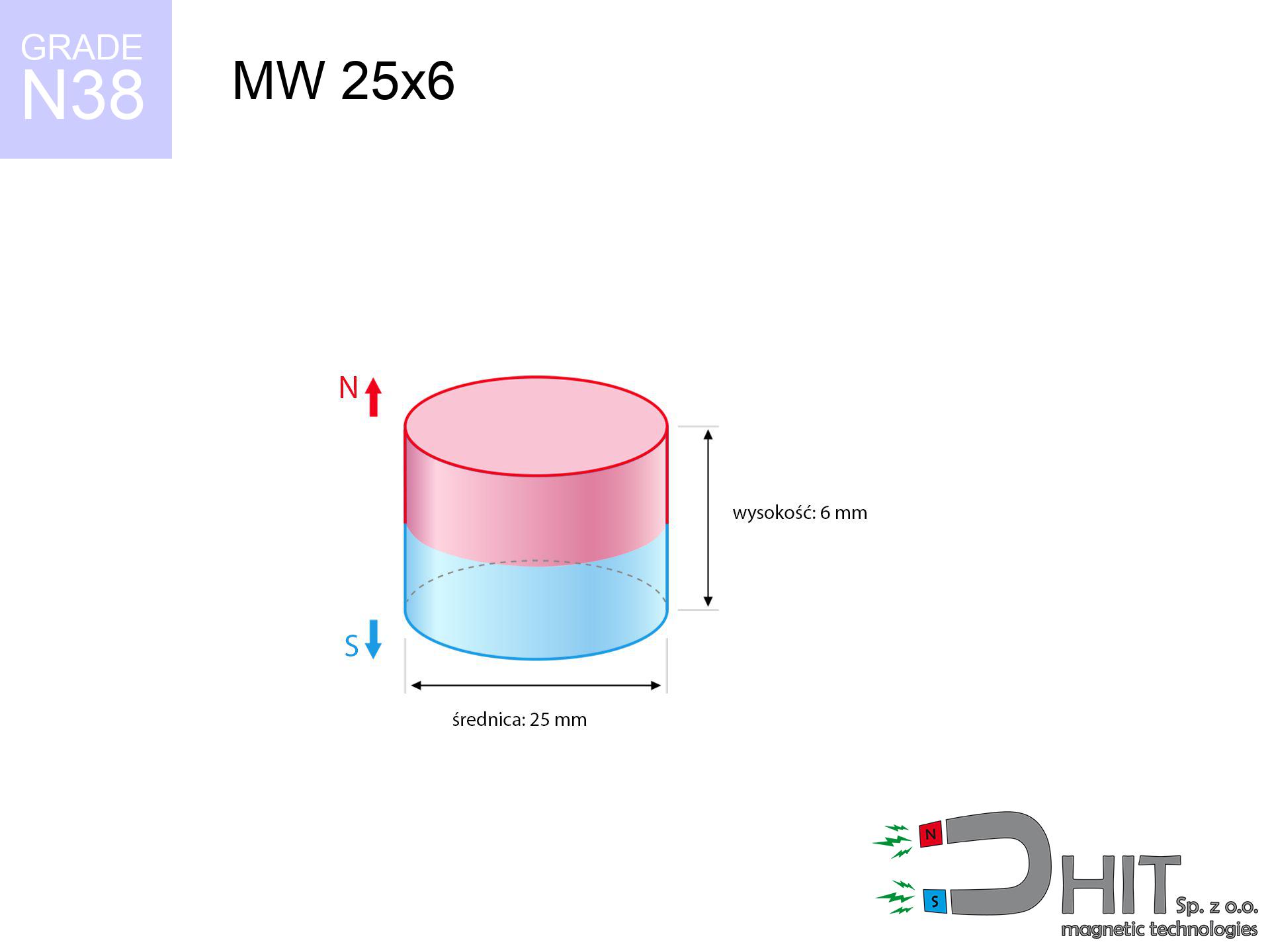
MW 25x6 / N38 - cylindrical magnet
cylindrical magnet
Catalog no 010050
GTIN/EAN: 5906301810490
- Diameter Ø
- 25 mm [±0,1 mm]
- Height
- 6 mm [±0,1 mm]
- Weight
- 22.09 g
- Magnetization Direction
- ↑ axial
- Coating
- [NiCuNi] Nickel
How we measure these parameters — certificates and measurements
6.02 zł net / pcs
7.40 zł with VAT (23% VAT) / pcs
bulk discounts:
Need more?Frequently asked questions
Where can I buy strong cylindrical neodymium magnets?
Can a small cylindrical magnet provide a strong grip for precise workshop work?
Which cylindrical magnet can work at a higher temperature?
Engineering report for this magnet
Full PDF analysis: pull and shear force, effect of distance, temperature and plate thickness, safety distances and the demagnetization curve.
Call us now
+48 888 99 98 98
alternatively let us know using
contact form
the contact section.
Specifications and structure of a neodymium magnet can be estimated using our
power calculator.
Order by 14:00 and we’ll ship today!
Physical properties - MW 25x6 / N38 - cylindrical magnet
Specification / characteristics - MW 25x6 / N38 - cylindrical magnet
| properties | values |
|---|---|
| Cat. no. | 010050 |
| GTIN/EAN | 5906301810490 |
| Production/Distribution | Dhit sp. z o.o. |
| Country of origin | Poland / China / Germany |
| Customs code | 85059029 |
| Diameter Ø | 25 mm [±0,1 mm] |
| Height | 6 mm [±0,1 mm] |
| Weight | 22.09 g |
| Magnetization Direction | ↑ axial |
| Load capacity ~ ? | 10.27 kg / 100.71 N |
| Magnetic Induction ~ ? | 268.21 mT / 2682 Gs |
| Coating | [NiCuNi] Nickel |
| Manufacturing Tolerance | ±0.1 mm |
Magnetic properties of material N38
| properties | values | units |
|---|---|---|
| Remanence Br ? | 12.2-12.6 | kGs |
| Remanence Br ? | 1220-1260 | mT |
| Coercivity bHc ? | 10.8-11.5 | kOe |
| Coercivity bHc ? | 860-915 | kA/m |
| Intrinsic coercivity iHc | ≥ 12 | kOe |
| Intrinsic coercivity iHc | ≥ 955 | kA/m |
| Energy product BHmax ? | 36-38 | BH max MGOe |
| Energy product BHmax ? | 287-303 | BH max KJ/m |
| Maximum working temperature ? | ≤ 80 | °C |
Physical properties of sintered neodymium magnets Nd2Fe14B at 20°C
| properties | values | units |
|---|---|---|
| Vickers hardness | ≥550 | Hv |
| Density | ≥7.4 | g/cm3 |
| Curie Temperature TC | 310 | °C |
| Curie Temperature TF | 590 | °F |
| Specific resistance | 150 | μΩ⋅cm |
| Bending strength | 250 | MPa |
| Compressive strength | 1000~1100 | MPa |
| Thermal expansion parallel (∥) to orientation (M) | (3-4) x 10-6 | °C-1 |
| Thermal expansion perpendicular (⊥) to orientation (M) | -(1-3) x 10-6 | °C-1 |
| Young's modulus | 1.7 x 10⁴ | kg/mm² |
Physical analysis of the magnet - data
These values constitute the outcome of a physical calculation. Values rely on algorithms for the material Nd2Fe14B. Real-world conditions may differ from theoretical values. Use these calculations as a reference point for designers.
Table 1: Static pull force (force vs distance) - power drop
MW 25x6 / N38
| Distance (mm) | Induction (Gauss) / mT | Pull Force (kg/lbs/g/N) | Risk Status |
|---|---|---|---|
| 0 mm |
2682 Gs
268.2 mT
|
10.27 kg / 22.64 lbs
10270.0 g / 100.7 N
|
crushing |
| 1 mm |
2535 Gs
253.5 mT
|
9.18 kg / 20.23 lbs
9177.2 g / 90.0 N
|
medium risk |
| 2 mm |
2363 Gs
236.3 mT
|
7.97 kg / 17.57 lbs
7971.8 g / 78.2 N
|
medium risk |
| 3 mm |
2176 Gs
217.6 mT
|
6.76 kg / 14.91 lbs
6761.0 g / 66.3 N
|
medium risk |
| 5 mm |
1793 Gs
179.3 mT
|
4.59 kg / 10.13 lbs
4592.7 g / 45.1 N
|
medium risk |
| 10 mm |
1013 Gs
101.3 mT
|
1.46 kg / 3.23 lbs
1464.5 g / 14.4 N
|
low risk |
| 15 mm |
565 Gs
56.5 mT
|
0.46 kg / 1.00 lbs
455.3 g / 4.5 N
|
low risk |
| 20 mm |
330 Gs
33.0 mT
|
0.16 kg / 0.34 lbs
155.7 g / 1.5 N
|
low risk |
| 30 mm |
134 Gs
13.4 mT
|
0.03 kg / 0.06 lbs
25.6 g / 0.3 N
|
low risk |
| 50 mm |
36 Gs
3.6 mT
|
0.00 kg / 0.00 lbs
1.9 g / 0.0 N
|
low risk |
Table 2: Shear capacity (wall)
MW 25x6 / N38
| Distance (mm) | Friction coefficient | Pull Force (kg/lbs/g/N) |
|---|---|---|
| 0 mm | Stal (~0.2) |
2.05 kg / 4.53 lbs
2054.0 g / 20.1 N
|
| 1 mm | Stal (~0.2) |
1.84 kg / 4.05 lbs
1836.0 g / 18.0 N
|
| 2 mm | Stal (~0.2) |
1.59 kg / 3.51 lbs
1594.0 g / 15.6 N
|
| 3 mm | Stal (~0.2) |
1.35 kg / 2.98 lbs
1352.0 g / 13.3 N
|
| 5 mm | Stal (~0.2) |
0.92 kg / 2.02 lbs
918.0 g / 9.0 N
|
| 10 mm | Stal (~0.2) |
0.29 kg / 0.64 lbs
292.0 g / 2.9 N
|
| 15 mm | Stal (~0.2) |
0.09 kg / 0.20 lbs
92.0 g / 0.9 N
|
| 20 mm | Stal (~0.2) |
0.03 kg / 0.07 lbs
32.0 g / 0.3 N
|
| 30 mm | Stal (~0.2) |
0.01 kg / 0.01 lbs
6.0 g / 0.1 N
|
| 50 mm | Stal (~0.2) |
0.00 kg / 0.00 lbs
0.0 g / 0.0 N
|
Table 3: Wall mounting (sliding) - vertical pull
MW 25x6 / N38
| Surface type | Friction coefficient / % Mocy | Max load (kg/lbs/g/N) |
|---|---|---|
| Raw steel |
µ = 0.3
30% Nominalnej Siły
|
3.08 kg / 6.79 lbs
3081.0 g / 30.2 N
|
| Painted steel (standard) |
µ = 0.2
20% Nominalnej Siły
|
2.05 kg / 4.53 lbs
2054.0 g / 20.1 N
|
| Oily/slippery steel |
µ = 0.1
10% Nominalnej Siły
|
1.03 kg / 2.26 lbs
1027.0 g / 10.1 N
|
| Magnet with anti-slip rubber |
µ = 0.5
50% Nominalnej Siły
|
5.14 kg / 11.32 lbs
5135.0 g / 50.4 N
|
Table 4: Steel thickness (saturation) - power losses
MW 25x6 / N38
| Steel thickness (mm) | % power | Real pull force (kg/lbs/g/N) |
|---|---|---|
| 0.5 mm |
|
0.51 kg / 1.13 lbs
513.5 g / 5.0 N
|
| 1 mm |
|
1.28 kg / 2.83 lbs
1283.8 g / 12.6 N
|
| 2 mm |
|
2.57 kg / 5.66 lbs
2567.5 g / 25.2 N
|
| 3 mm |
|
3.85 kg / 8.49 lbs
3851.3 g / 37.8 N
|
| 5 mm |
|
6.42 kg / 14.15 lbs
6418.7 g / 63.0 N
|
| 10 mm |
|
10.27 kg / 22.64 lbs
10270.0 g / 100.7 N
|
| 11 mm |
|
10.27 kg / 22.64 lbs
10270.0 g / 100.7 N
|
| 12 mm |
|
10.27 kg / 22.64 lbs
10270.0 g / 100.7 N
|
Table 5: Thermal resistance (material behavior) - thermal limit
MW 25x6 / N38
| Ambient temp. (°C) | Power loss | Remaining pull (kg/lbs/g/N) | Status |
|---|---|---|---|
| 20 °C | 0.0% |
10.27 kg / 22.64 lbs
10270.0 g / 100.7 N
|
OK |
| 40 °C | -2.2% |
10.04 kg / 22.14 lbs
10044.1 g / 98.5 N
|
OK |
| 60 °C | -4.4% |
9.82 kg / 21.65 lbs
9818.1 g / 96.3 N
|
|
| 80 °C | -6.6% |
9.59 kg / 21.15 lbs
9592.2 g / 94.1 N
|
|
| 100 °C | -28.8% |
7.31 kg / 16.12 lbs
7312.2 g / 71.7 N
|
Table 6: Magnet-Magnet interaction (attraction) - forces in the system
MW 25x6 / N38
| Gap (mm) | Attraction (kg/lbs) (N-S) | Sliding Force (kg/lbs/g/N) | Repulsion (kg/lbs) (N-N) |
|---|---|---|---|
| 0 mm |
21.76 kg / 47.98 lbs
4 291 Gs
|
3.26 kg / 7.20 lbs
3264 g / 32.0 N
|
N/A |
| 1 mm |
20.66 kg / 45.54 lbs
5 225 Gs
|
3.10 kg / 6.83 lbs
3098 g / 30.4 N
|
18.59 kg / 40.98 lbs
~0 Gs
|
| 2 mm |
19.45 kg / 42.87 lbs
5 070 Gs
|
2.92 kg / 6.43 lbs
2917 g / 28.6 N
|
17.50 kg / 38.58 lbs
~0 Gs
|
| 3 mm |
18.18 kg / 40.09 lbs
4 902 Gs
|
2.73 kg / 6.01 lbs
2727 g / 26.8 N
|
16.36 kg / 36.08 lbs
~0 Gs
|
| 5 mm |
15.60 kg / 34.39 lbs
4 541 Gs
|
2.34 kg / 5.16 lbs
2340 g / 23.0 N
|
14.04 kg / 30.95 lbs
~0 Gs
|
| 10 mm |
9.73 kg / 21.46 lbs
3 587 Gs
|
1.46 kg / 3.22 lbs
1460 g / 14.3 N
|
8.76 kg / 19.31 lbs
~0 Gs
|
| 20 mm |
3.10 kg / 6.84 lbs
2 025 Gs
|
0.47 kg / 1.03 lbs
465 g / 4.6 N
|
2.79 kg / 6.16 lbs
~0 Gs
|
| 50 mm |
0.13 kg / 0.28 lbs
409 Gs
|
0.02 kg / 0.04 lbs
19 g / 0.2 N
|
0.11 kg / 0.25 lbs
~0 Gs
|
| 60 mm |
0.05 kg / 0.12 lbs
268 Gs
|
0.01 kg / 0.02 lbs
8 g / 0.1 N
|
0.05 kg / 0.11 lbs
~0 Gs
|
| 70 mm |
0.03 kg / 0.06 lbs
183 Gs
|
0.00 kg / 0.01 lbs
4 g / 0.0 N
|
0.02 kg / 0.05 lbs
~0 Gs
|
| 80 mm |
0.01 kg / 0.03 lbs
131 Gs
|
0.00 kg / 0.00 lbs
2 g / 0.0 N
|
0.01 kg / 0.03 lbs
~0 Gs
|
| 90 mm |
0.01 kg / 0.02 lbs
96 Gs
|
0.00 kg / 0.00 lbs
1 g / 0.0 N
|
0.00 kg / 0.00 lbs
~0 Gs
|
| 100 mm |
0.00 kg / 0.01 lbs
72 Gs
|
0.00 kg / 0.00 lbs
1 g / 0.0 N
|
0.00 kg / 0.00 lbs
~0 Gs
|
Table 7: Safety (HSE) (electronics) - warnings
MW 25x6 / N38
| Object / Device | Limit (Gauss) / mT | Safe distance |
|---|---|---|
| Pacemaker | 5 Gs (0.5 mT) | 10.5 cm |
| Hearing aid | 10 Gs (1.0 mT) | 8.0 cm |
| Mechanical watch | 20 Gs (2.0 mT) | 6.5 cm |
| Phone / Smartphone | 40 Gs (4.0 mT) | 5.0 cm |
| Remote | 50 Gs (5.0 mT) | 4.5 cm |
| Payment card | 400 Gs (40.0 mT) | 2.0 cm |
| HDD hard drive | 600 Gs (60.0 mT) | 1.5 cm |
Table 8: Impact energy (cracking risk) - warning
MW 25x6 / N38
| Start from (mm) | Speed (km/h) | Energy (J) | Predicted outcome |
|---|---|---|---|
| 10 mm |
24.18 km/h
(6.72 m/s)
|
0.50 J | |
| 30 mm |
25.66 km/h
(7.13 m/s)
|
0.56 J | |
| 50 mm |
25.69 km/h
(7.14 m/s)
|
0.56 J | |
| 100 mm |
25.70 km/h
(7.14 m/s)
|
0.56 J |
Table 9: Anti-corrosion coating durability
MW 25x6 / N38
| Technical parameter | Value / Description |
|---|---|
| Coating type | [NiCuNi] Nickel |
| Layer structure | Nickel - Copper - Nickel |
| Layer thickness | 10-20 µm |
| Salt spray test (SST) ? | 24 h |
| Recommended environment | Indoors only (dry) |
Table 10: Electrical data (Pc)
MW 25x6 / N38
| Parameter | Value | SI Unit / Description |
|---|---|---|
| Magnetic Flux | 14 740 Mx | 147.4 µWb |
| Pc Coefficient | 0.34 | Low (Flat) |
Table 11: Physics of underwater searching
MW 25x6 / N38
| Environment | Effective steel pull | Effect |
|---|---|---|
| Air (land) | 10.27 kg | Standard |
| Water (riverbed) |
11.76 kg
(+1.49 kg buoyancy gain)
|
+14.5% |
1. Sliding resistance
*Warning: On a vertical wall, the magnet retains just ~20% of its nominal pull.
2. Steel thickness impact
*Thin steel (e.g. 0.5mm PC case) severely weakens the holding force.
3. Thermal stability
N38: the maximum material working temperature is 80°C. Permitted conditions also depend on the shape and magnetic circuit.
4. Demagnetization curve and operating point (B-H)
chart generated for the permeance coefficient Pc (Permeance Coefficient) = 0.34
This simulation demonstrates the magnetic stability of the selected magnet under specific geometric conditions. The solid red line represents the demagnetization curve (material potential), while the dashed blue line is the load line based on the magnet's geometry. The Pc (Permeance Coefficient), also known as the load line slope, is a dimensionless value that describes the relationship between the magnet's shape and its magnetic stability. The intersection of these two lines (the black dot) is the operating point — it determines the actual magnetic flux density generated by the magnet in this specific configuration. A higher Pc value means the magnet is more 'slender' (tall relative to its area), resulting in a higher operating point and better resistance to irreversible demagnetization caused by external fields or temperature. A value of 0.42 is relatively low (typical for flat magnets), meaning the operating point is closer to the 'knee' of the curve — caution is advised when operating at temperatures near the maximum limit to avoid strength loss.
Material specification
| iron (Fe) | 64% – 68% |
| neodymium (Nd) | 29% – 32% |
| boron (B) | 1.1% – 1.2% |
| dysprosium (Dy) | 0.5% – 2.0% |
| coating (Ni-Cu-Ni) | < 0.05% |
Ecology and recycling (GPSR)
| recyclability (EoL) | 100% |
| recycled raw materials | ~10% (pre-cons) |
| carbon footprint | low / zredukowany |
| waste code (EWC) | 16 02 16 |
Check out more offers

![UMGGZ 66x8.5 [M8] GZ / N38 - rubber magnetic holder external thread](https://cdn3.dhit.pl/graphics/products/umggz-66x8.5-m6-gz-gas.jpg "UMGGZ 66x8.5 [M8] GZ / N38 - rubber magnetic holder external thread")
![SM 32x500 [2xM8] / N42 - magnetic separator](https://cdn3.dhit.pl/graphics/products/sm-32x500-2xm8-jan.jpg "SM 32x500 [2xM8] / N42 - magnetic separator")
Pros as well as cons of Nd2Fe14B magnets.
Strengths
- They virtually do not lose strength, because even after ten years the decline in efficiency is only ~1% (based on calculations),
- Neodymium magnets are characterized by remarkably resistant to demagnetization caused by external field sources,
- In other words, due to the glossy layer of nickel, the element is aesthetically pleasing,
- The surface of neodymium magnets generates a strong magnetic field – this is a distinguishing feature,
- Due to their durability and thermal resistance, neodymium magnets are capable of operate (depending on the form) even at high temperatures reaching 230°C or more...
- Possibility of detailed forming and modifying to individual applications,
- Significant place in innovative solutions – they are commonly used in magnetic memories, electric motors, medical equipment, as well as complex engineering applications.
- Relatively small size with high pulling force – neodymium magnets offer high power in compact dimensions, which enables their usage in small systems
Disadvantages
- They are fragile upon too strong impacts. To avoid cracks, it is worth securing magnets in a protective case. Such protection not only shields the magnet but also increases its resistance to damage
- Do not exceed this material temperature limit: 80°C. Overheating may permanently weaken the magnet.
- Magnets exposed to a humid environment can corrode. Therefore when using outdoors, we recommend using waterproof magnets made of rubber, plastic or other material resistant to moisture
- Limited possibility of making threads in the magnet and complex shapes - recommended is cover - mounting mechanism.
- Health risk to health – tiny shards of magnets can be dangerous, in case of ingestion, which gains importance in the context of child safety. Additionally, tiny parts of these magnets are able to be problematic in diagnostics medical in case of swallowing.
- With budget limitations the cost of neodymium magnets is a challenge,
Holding force characteristics
Maximum holding power of the magnet – what affects it?
- with the application of a yoke made of special test steel, ensuring maximum field concentration
- possessing a thickness of minimum 10 mm to ensure full flux closure
- with a surface cleaned and smooth
- with total lack of distance (without impurities)
- for force applied at a right angle (pull-off, not shear)
- at ambient temperature approx. 20 degrees Celsius
Determinants of lifting force in real conditions
- Distance – the presence of foreign body (paint, dirt, gap) interrupts the magnetic circuit, which lowers power steeply (even by 50% at 0.5 mm).
- Pull-off angle – remember that the magnet holds strongest perpendicularly. Under sliding down, the holding force drops significantly, often to levels of 20-30% of the nominal value.
- Element thickness – for full efficiency, the steel must be adequately massive. Paper-thin metal limits the lifting capacity (the magnet "punches through" it).
- Chemical composition of the base – mild steel gives the best results. Higher carbon content lower magnetic properties and holding force.
- Smoothness – ideal contact is obtained only on polished steel. Rough texture create air cushions, weakening the magnet.
- Temperature influence – hot environment weakens magnetic field. Too high temperature can permanently damage the magnet.
Lifting capacity testing was carried out on a smooth plate of optimal thickness, under perpendicular forces, in contrast under attempts to slide the magnet the load capacity is reduced by as much as 5 times. Moreover, even a slight gap between the magnet’s surface and the plate decreases the load capacity.
H&S for magnets
Adults only
Adult use only. Small elements can be swallowed, leading to intestinal necrosis. Keep out of reach of kids and pets.
Do not overheat magnets
Watch the temperature. Exposing the magnet above 80 degrees Celsius will destroy its magnetic structure and pulling force.
Impact on smartphones
A strong magnetic field interferes with the functioning of compasses in phones and GPS navigation. Do not bring magnets close to a smartphone to avoid damaging the sensors.
Data carriers
Very strong magnetic fields can erase data on payment cards, hard drives, and other magnetic media. Keep a distance of min. 10 cm.
Avoid contact if allergic
Allergy Notice: The nickel-copper-nickel coating consists of nickel. If an allergic reaction appears, cease handling magnets and wear gloves.
Shattering risk
Despite metallic appearance, neodymium is brittle and not impact-resistant. Avoid impacts, as the magnet may crumble into sharp, dangerous pieces.
Crushing force
Large magnets can crush fingers instantly. Under no circumstances put your hand betwixt two strong magnets.
Medical implants
For implant holders: Powerful magnets affect medical devices. Keep at least 30 cm distance or ask another person to work with the magnets.
Caution required
Use magnets consciously. Their huge power can surprise even experienced users. Plan your moves and respect their power.
Do not drill into magnets
Combustion risk: Neodymium dust is highly flammable. Do not process magnets without safety gear as this may cause fire.
Tabela kosztu i czasu dostawy
Płatność przed wysyłką:

GLS kurier
Przesyłka będzie u Ciebie za 2-3 dni
14.99 ZŁ

InPost Paczkomaty 24/7
Przesyłka będzie u Ciebie za 1-2 dni
12.30 ZŁ
Płatność przy odbiorze (pobranie):
GLS kurier
Przesyłka będzie u Ciebie za 1-2 dni
23.00 ZŁ