

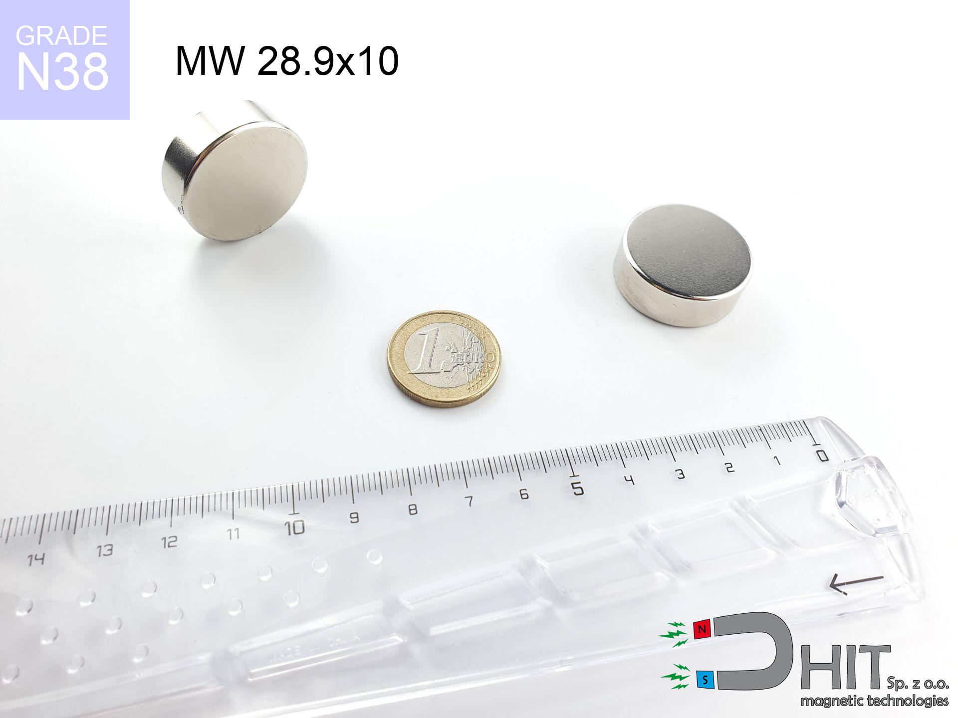
MW 28.9x10 / N38 - cylindrical magnet
cylindrical magnet
Catalog no 010051
GTIN/EAN: 5906301810506
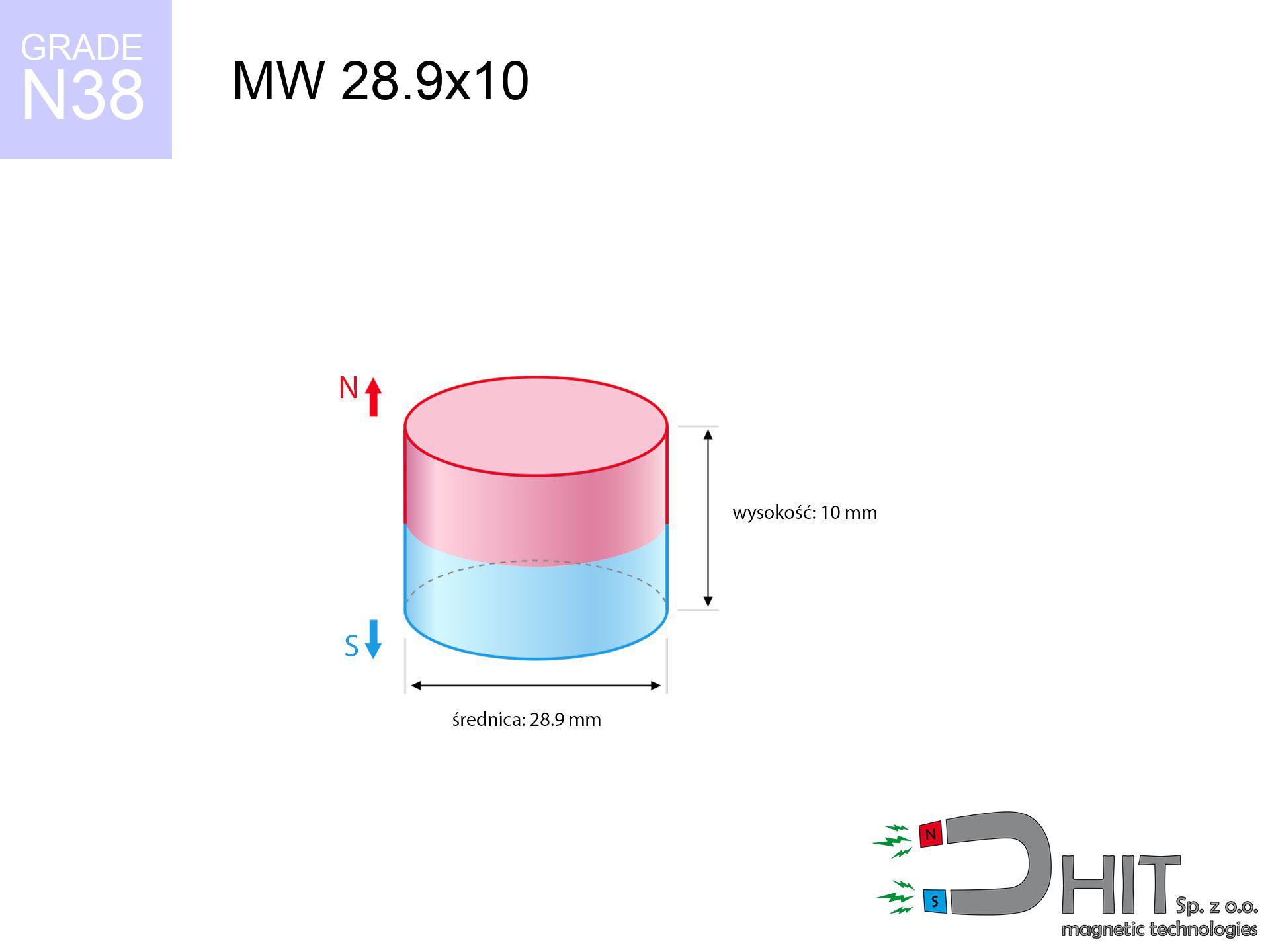
- Diameter Ø
- 28.9 mm [±0,1 mm]
- Height
- 10 mm [±0,1 mm]
- Weight
- 49.2 g
- Magnetization Direction
- → diametrical
- Coating
- [NiCuNi] Nickel
How we measure these parameters — certificates and measurements
19.50 zł net / pcs
23.99 zł with VAT (23% VAT) / pcs
bulk discounts:
Need more?Frequently asked questions
Where can I buy strong cylindrical neodymium magnets?
Can a small cylindrical magnet provide a strong grip for precise workshop work?
Which cylindrical magnet can work at a higher temperature?
Call us now
+48 888 99 98 98
alternatively let us know using
contact form
the contact section.
Specifications and structure of a neodymium magnet can be estimated using our
power calculator.
Order by 14:00 and we’ll ship today!
Product card - MW 28.9x10 / N38 - cylindrical magnet
Specification / characteristics - MW 28.9x10 / N38 - cylindrical magnet
| properties | values |
|---|---|
| Cat. no. | 010051 |
| GTIN/EAN | 5906301810506 |
| Production/Distribution | Dhit sp. z o.o. |
| Country of origin | Poland / China / Germany |
| Customs code | 85059029 |
| Diameter Ø | 28.9 mm [±0,1 mm] |
| Height | 10 mm [±0,1 mm] |
| Weight | 49.2 g |
| Magnetization Direction | → diametrical |
| Load capacity ~ ? | 20.74 kg / 203.46 N |
| Magnetic Induction ~ ? | 352.70 mT / 3527 Gs |
| Coating | [NiCuNi] Nickel |
| Manufacturing Tolerance | ±0.1 mm |
Magnetic properties of material N38
| properties | values | units |
|---|---|---|
| Remanence Br ? | 12.2-12.6 | kGs |
| Remanence Br ? | 1220-1260 | mT |
| Coercivity bHc ? | 10.8-11.5 | kOe |
| Coercivity bHc ? | 860-915 | kA/m |
| Intrinsic coercivity iHc | ≥ 12 | kOe |
| Intrinsic coercivity iHc | ≥ 955 | kA/m |
| Energy product BHmax ? | 36-38 | BH max MGOe |
| Energy product BHmax ? | 287-303 | BH max KJ/m |
| Maximum working temperature ? | ≤ 80 | °C |
Physical properties of sintered neodymium magnets Nd2Fe14B at 20°C
| properties | values | units |
|---|---|---|
| Vickers hardness | ≥550 | Hv |
| Density | ≥7.4 | g/cm3 |
| Curie Temperature TC | 310 | °C |
| Curie Temperature TF | 590 | °F |
| Specific resistance | 150 | μΩ⋅cm |
| Bending strength | 250 | MPa |
| Compressive strength | 1000~1100 | MPa |
| Thermal expansion parallel (∥) to orientation (M) | (3-4) x 10-6 | °C-1 |
| Thermal expansion perpendicular (⊥) to orientation (M) | -(1-3) x 10-6 | °C-1 |
| Young's modulus | 1.7 x 10⁴ | kg/mm² |
Technical simulation of the product - report
Presented information are the direct effect of a physical calculation. Values rely on algorithms for the class Nd2Fe14B. Actual performance might slightly deviate from the simulation results. Use these calculations as a supplementary guide when designing systems.
Table 1: Static pull force (pull vs gap) - power drop
MW 28.9x10 / N38
| Distance (mm) | Induction (Gauss) / mT | Pull Force (kg/lbs/g/N) | Risk Status |
|---|---|---|---|
| 0 mm |
3526 Gs
352.6 mT
|
20.74 kg / 45.72 LBS
20740.0 g / 203.5 N
|
crushing |
| 1 mm |
3327 Gs
332.7 mT
|
18.47 kg / 40.71 LBS
18466.2 g / 181.2 N
|
crushing |
| 2 mm |
3111 Gs
311.1 mT
|
16.14 kg / 35.59 LBS
16142.6 g / 158.4 N
|
crushing |
| 3 mm |
2886 Gs
288.6 mT
|
13.90 kg / 30.63 LBS
13895.8 g / 136.3 N
|
crushing |
| 5 mm |
2438 Gs
243.8 mT
|
9.91 kg / 21.85 LBS
9912.0 g / 97.2 N
|
medium risk |
| 10 mm |
1497 Gs
149.7 mT
|
3.74 kg / 8.24 LBS
3739.6 g / 36.7 N
|
medium risk |
| 15 mm |
903 Gs
90.3 mT
|
1.36 kg / 3.00 LBS
1359.1 g / 13.3 N
|
safe |
| 20 mm |
560 Gs
56.0 mT
|
0.52 kg / 1.15 LBS
523.5 g / 5.1 N
|
safe |
| 30 mm |
245 Gs
24.5 mT
|
0.10 kg / 0.22 LBS
100.4 g / 1.0 N
|
safe |
| 50 mm |
71 Gs
7.1 mT
|
0.01 kg / 0.02 LBS
8.5 g / 0.1 N
|
safe |
Table 2: Shear load (vertical surface)
MW 28.9x10 / N38
| Distance (mm) | Friction coefficient | Pull Force (kg/lbs/g/N) |
|---|---|---|
| 0 mm | Stal (~0.2) |
4.15 kg / 9.14 LBS
4148.0 g / 40.7 N
|
| 1 mm | Stal (~0.2) |
3.69 kg / 8.14 LBS
3694.0 g / 36.2 N
|
| 2 mm | Stal (~0.2) |
3.23 kg / 7.12 LBS
3228.0 g / 31.7 N
|
| 3 mm | Stal (~0.2) |
2.78 kg / 6.13 LBS
2780.0 g / 27.3 N
|
| 5 mm | Stal (~0.2) |
1.98 kg / 4.37 LBS
1982.0 g / 19.4 N
|
| 10 mm | Stal (~0.2) |
0.75 kg / 1.65 LBS
748.0 g / 7.3 N
|
| 15 mm | Stal (~0.2) |
0.27 kg / 0.60 LBS
272.0 g / 2.7 N
|
| 20 mm | Stal (~0.2) |
0.10 kg / 0.23 LBS
104.0 g / 1.0 N
|
| 30 mm | Stal (~0.2) |
0.02 kg / 0.04 LBS
20.0 g / 0.2 N
|
| 50 mm | Stal (~0.2) |
0.00 kg / 0.00 LBS
2.0 g / 0.0 N
|
Table 3: Wall mounting (sliding) - behavior on slippery surfaces
MW 28.9x10 / N38
| Surface type | Friction coefficient / % Mocy | Max load (kg/lbs/g/N) |
|---|---|---|
| Raw steel |
µ = 0.3
30% Nominalnej Siły
|
6.22 kg / 13.72 LBS
6222.0 g / 61.0 N
|
| Painted steel (standard) |
µ = 0.2
20% Nominalnej Siły
|
4.15 kg / 9.14 LBS
4148.0 g / 40.7 N
|
| Oily/slippery steel |
µ = 0.1
10% Nominalnej Siły
|
2.07 kg / 4.57 LBS
2074.0 g / 20.3 N
|
| Magnet with anti-slip rubber |
µ = 0.5
50% Nominalnej Siły
|
10.37 kg / 22.86 LBS
10370.0 g / 101.7 N
|
Table 4: Material efficiency (substrate influence) - sheet metal selection
MW 28.9x10 / N38
| Steel thickness (mm) | % power | Real pull force (kg/lbs/g/N) |
|---|---|---|
| 0.5 mm |
|
1.04 kg / 2.29 LBS
1037.0 g / 10.2 N
|
| 1 mm |
|
2.59 kg / 5.72 LBS
2592.5 g / 25.4 N
|
| 2 mm |
|
5.19 kg / 11.43 LBS
5185.0 g / 50.9 N
|
| 3 mm |
|
7.78 kg / 17.15 LBS
7777.5 g / 76.3 N
|
| 5 mm |
|
12.96 kg / 28.58 LBS
12962.5 g / 127.2 N
|
| 10 mm |
|
20.74 kg / 45.72 LBS
20740.0 g / 203.5 N
|
| 11 mm |
|
20.74 kg / 45.72 LBS
20740.0 g / 203.5 N
|
| 12 mm |
|
20.74 kg / 45.72 LBS
20740.0 g / 203.5 N
|
Table 5: Thermal stability (stability) - thermal limit
MW 28.9x10 / N38
| Ambient temp. (°C) | Power loss | Remaining pull (kg/lbs/g/N) | Status |
|---|---|---|---|
| 20 °C | 0.0% |
20.74 kg / 45.72 LBS
20740.0 g / 203.5 N
|
OK |
| 40 °C | -2.2% |
20.28 kg / 44.72 LBS
20283.7 g / 199.0 N
|
OK |
| 60 °C | -4.4% |
19.83 kg / 43.71 LBS
19827.4 g / 194.5 N
|
|
| 80 °C | -6.6% |
19.37 kg / 42.71 LBS
19371.2 g / 190.0 N
|
|
| 100 °C | -28.8% |
14.77 kg / 32.56 LBS
14766.9 g / 144.9 N
|
Table 6: Two magnets (repulsion) - field collision
MW 28.9x10 / N38
| Gap (mm) | Attraction (kg/lbs) (N-S) | Shear Strength (kg/lbs/g/N) | Repulsion (kg/lbs) (N-N) |
|---|---|---|---|
| 0 mm |
50.29 kg / 110.86 LBS
5 022 Gs
|
7.54 kg / 16.63 LBS
7543 g / 74.0 N
|
N/A |
| 1 mm |
47.58 kg / 104.90 LBS
6 860 Gs
|
7.14 kg / 15.74 LBS
7138 g / 70.0 N
|
42.83 kg / 94.41 LBS
~0 Gs
|
| 2 mm |
44.77 kg / 98.71 LBS
6 655 Gs
|
6.72 kg / 14.81 LBS
6716 g / 65.9 N
|
40.30 kg / 88.84 LBS
~0 Gs
|
| 3 mm |
41.95 kg / 92.48 LBS
6 441 Gs
|
6.29 kg / 13.87 LBS
6292 g / 61.7 N
|
37.75 kg / 83.23 LBS
~0 Gs
|
| 5 mm |
36.38 kg / 80.20 LBS
5 999 Gs
|
5.46 kg / 12.03 LBS
5457 g / 53.5 N
|
32.74 kg / 72.18 LBS
~0 Gs
|
| 10 mm |
24.03 kg / 52.98 LBS
4 876 Gs
|
3.60 kg / 7.95 LBS
3605 g / 35.4 N
|
21.63 kg / 47.69 LBS
~0 Gs
|
| 20 mm |
9.07 kg / 19.99 LBS
2 995 Gs
|
1.36 kg / 3.00 LBS
1360 g / 13.3 N
|
8.16 kg / 17.99 LBS
~0 Gs
|
| 50 mm |
0.53 kg / 1.17 LBS
726 Gs
|
0.08 kg / 0.18 LBS
80 g / 0.8 N
|
0.48 kg / 1.06 LBS
~0 Gs
|
| 60 mm |
0.24 kg / 0.54 LBS
491 Gs
|
0.04 kg / 0.08 LBS
37 g / 0.4 N
|
0.22 kg / 0.48 LBS
~0 Gs
|
| 70 mm |
0.12 kg / 0.26 LBS
345 Gs
|
0.02 kg / 0.04 LBS
18 g / 0.2 N
|
0.11 kg / 0.24 LBS
~0 Gs
|
| 80 mm |
0.06 kg / 0.14 LBS
250 Gs
|
0.01 kg / 0.02 LBS
9 g / 0.1 N
|
0.06 kg / 0.13 LBS
~0 Gs
|
| 90 mm |
0.04 kg / 0.08 LBS
187 Gs
|
0.01 kg / 0.01 LBS
5 g / 0.1 N
|
0.03 kg / 0.07 LBS
~0 Gs
|
| 100 mm |
0.02 kg / 0.05 LBS
143 Gs
|
0.00 kg / 0.01 LBS
3 g / 0.0 N
|
0.02 kg / 0.04 LBS
~0 Gs
|
Table 7: Protective zones (electronics) - warnings
MW 28.9x10 / N38
| Object / Device | Limit (Gauss) / mT | Safe distance |
|---|---|---|
| Pacemaker | 5 Gs (0.5 mT) | 13.5 cm |
| Hearing aid | 10 Gs (1.0 mT) | 10.5 cm |
| Mechanical watch | 20 Gs (2.0 mT) | 8.5 cm |
| Phone / Smartphone | 40 Gs (4.0 mT) | 6.5 cm |
| Car key | 50 Gs (5.0 mT) | 6.0 cm |
| Payment card | 400 Gs (40.0 mT) | 2.5 cm |
| HDD hard drive | 600 Gs (60.0 mT) | 2.0 cm |
Table 8: Dynamics (kinetic energy) - warning
MW 28.9x10 / N38
| Start from (mm) | Speed (km/h) | Energy (J) | Predicted outcome |
|---|---|---|---|
| 10 mm |
23.58 km/h
(6.55 m/s)
|
1.06 J | |
| 30 mm |
25.54 km/h
(7.09 m/s)
|
1.24 J | |
| 50 mm |
25.61 km/h
(7.11 m/s)
|
1.24 J | |
| 100 mm |
25.62 km/h
(7.12 m/s)
|
1.25 J |
Table 9: Surface protection spec
MW 28.9x10 / N38
| Technical parameter | Value / Description |
|---|---|
| Coating type | [NiCuNi] Nickel |
| Layer structure | Nickel - Copper - Nickel |
| Layer thickness | 10-20 µm |
| Salt spray test (SST) ? | 24 h |
| Recommended environment | Indoors only (dry) |
Table 10: Construction data (Pc)
MW 28.9x10 / N38
| Parameter | Value | SI Unit / Description |
|---|---|---|
| Magnetic Flux | 24 347 Mx | 243.5 µWb |
| Pc Coefficient | 0.45 | Low (Flat) |
Table 11: Submerged application
MW 28.9x10 / N38
| Environment | Effective steel pull | Effect |
|---|---|---|
| Air (land) | 20.74 kg | Standard |
| Water (riverbed) |
23.75 kg
(+3.01 kg buoyancy gain)
|
+14.5% |
1. Sliding resistance
*Warning: On a vertical surface, the magnet holds merely a fraction of its perpendicular strength.
2. Plate thickness effect
*Thin steel (e.g. 0.5mm PC case) drastically weakens the holding force.
3. Thermal stability
N38: the maximum material working temperature is 80°C. Permitted conditions also depend on the shape and magnetic circuit.
4. Demagnetization curve and operating point (B-H)
chart generated for the permeance coefficient Pc (Permeance Coefficient) = 0.45
This simulation demonstrates the magnetic stability of the selected magnet under specific geometric conditions. The solid red line represents the demagnetization curve (material potential), while the dashed blue line is the load line based on the magnet's geometry. The Pc (Permeance Coefficient), also known as the load line slope, is a dimensionless value that describes the relationship between the magnet's shape and its magnetic stability. The intersection of these two lines (the black dot) is the operating point — it determines the actual magnetic flux density generated by the magnet in this specific configuration. A higher Pc value means the magnet is more 'slender' (tall relative to its area), resulting in a higher operating point and better resistance to irreversible demagnetization caused by external fields or temperature. A value of 0.42 is relatively low (typical for flat magnets), meaning the operating point is closer to the 'knee' of the curve — caution is advised when operating at temperatures near the maximum limit to avoid strength loss.
Material specification
| iron (Fe) | 64% – 68% |
| neodymium (Nd) | 29% – 32% |
| boron (B) | 1.1% – 1.2% |
| dysprosium (Dy) | 0.5% – 2.0% |
| coating (Ni-Cu-Ni) | < 0.05% |
Environmental data
| recyclability (EoL) | 100% |
| recycled raw materials | ~10% (pre-cons) |
| carbon footprint | low / zredukowany |
| waste code (EWC) | 16 02 16 |
Other offers

Strengths as well as weaknesses of Nd2Fe14B magnets.
Strengths
- They have stable power, and over around 10 years their performance decreases symbolically – ~1% (according to theory),
- They possess excellent resistance to magnetism drop due to external magnetic sources,
- A magnet with a smooth nickel surface is more attractive,
- Neodymium magnets generate maximum magnetic induction on a contact point, which allows for strong attraction,
- Through (adequate) combination of ingredients, they can achieve high thermal strength, allowing for operation at temperatures approaching 230°C and above...
- Thanks to versatility in shaping and the ability to customize to specific needs,
- Huge importance in electronics industry – they find application in data components, brushless drives, medical devices, as well as industrial machines.
- Relatively small size with high pulling force – neodymium magnets offer high power in compact dimensions, which makes them useful in compact constructions
Disadvantages
- At very strong impacts they can crack, therefore we advise placing them in strong housings. A metal housing provides additional protection against damage and increases the magnet's durability.
- Do not exceed this material temperature limit: 80°C. Overheating may permanently weaken the magnet.
- When exposed to humidity, magnets start to rust. To use them in conditions outside, it is recommended to use protective magnets, such as those in rubber or plastics, which prevent oxidation and corrosion.
- Limited possibility of creating threads in the magnet and complex shapes - recommended is casing - mounting mechanism.
- Possible danger to health – tiny shards of magnets pose a threat, when accidentally swallowed, which becomes key in the context of child safety. It is also worth noting that tiny parts of these devices are able to be problematic in diagnostics medical in case of swallowing.
- Higher cost of purchase is one of the disadvantages compared to ceramic magnets, especially in budget applications
Holding force characteristics
Maximum lifting force for a neodymium magnet – what affects it?
- using a sheet made of mild steel, serving as a magnetic yoke
- possessing a thickness of min. 10 mm to avoid saturation
- characterized by lack of roughness
- without any air gap between the magnet and steel
- for force applied at a right angle (pull-off, not shear)
- at temperature room level
Impact of factors on magnetic holding capacity in practice
- Space between magnet and steel – every millimeter of distance (caused e.g. by varnish or unevenness) significantly weakens the magnet efficiency, often by half at just 0.5 mm.
- Force direction – declared lifting capacity refers to pulling vertically. When slipping, the magnet holds significantly lower power (typically approx. 20-30% of nominal force).
- Wall thickness – thin material does not allow full use of the magnet. Part of the magnetic field passes through the material instead of generating force.
- Metal type – not every steel attracts identically. High carbon content weaken the attraction effect.
- Base smoothness – the more even the surface, the better the adhesion and higher the lifting capacity. Unevenness acts like micro-gaps.
- Temperature – temperature increase causes a temporary drop of force. It is worth remembering the maximum operating temperature for a given model.
Holding force was measured on a smooth steel plate of 20 mm thickness, when the force acted perpendicularly, in contrast under shearing force the holding force is lower. Moreover, even a small distance between the magnet’s surface and the plate reduces the holding force.
Safe handling of NdFeB magnets
Pinching danger
Big blocks can break fingers in a fraction of a second. Never place your hand between two attracting surfaces.
Safe distance
Device Safety: Strong magnets can ruin data carriers and sensitive devices (pacemakers, medical aids, timepieces).
Maximum temperature
Do not overheat. NdFeB magnets are sensitive to temperature. If you need resistance above 80°C, inquire about HT versions (H, SH, UH).
Shattering risk
Watch out for shards. Magnets can explode upon violent connection, ejecting shards into the air. Wear goggles.
Sensitization to coating
Nickel alert: The Ni-Cu-Ni coating contains nickel. If skin irritation occurs, immediately stop handling magnets and use protective gear.
Do not underestimate power
Handle with care. Neodymium magnets act from a distance and snap with huge force, often faster than you can move away.
Mechanical processing
Dust created during machining of magnets is self-igniting. Avoid drilling into magnets without proper cooling and knowledge.
GPS and phone interference
An intense magnetic field interferes with the functioning of magnetometers in smartphones and navigation systems. Maintain magnets near a device to prevent breaking the sensors.
ICD Warning
Patients with a pacemaker should maintain an absolute distance from magnets. The magnetic field can interfere with the functioning of the implant.
Product not for children
These products are not suitable for play. Accidental ingestion of several magnets can lead to them attracting across intestines, which poses a direct threat to life and requires immediate surgery.
Tabela kosztu i czasu dostawy
Płatność przed wysyłką:

GLS kurier
Przesyłka będzie u Ciebie za 2-3 dni
14.99 ZŁ

InPost Paczkomaty 24/7
Przesyłka będzie u Ciebie za 1-2 dni
12.30 ZŁ
Płatność przy odbiorze (pobranie):
GLS kurier
Przesyłka będzie u Ciebie za 1-2 dni
23.00 ZŁ