

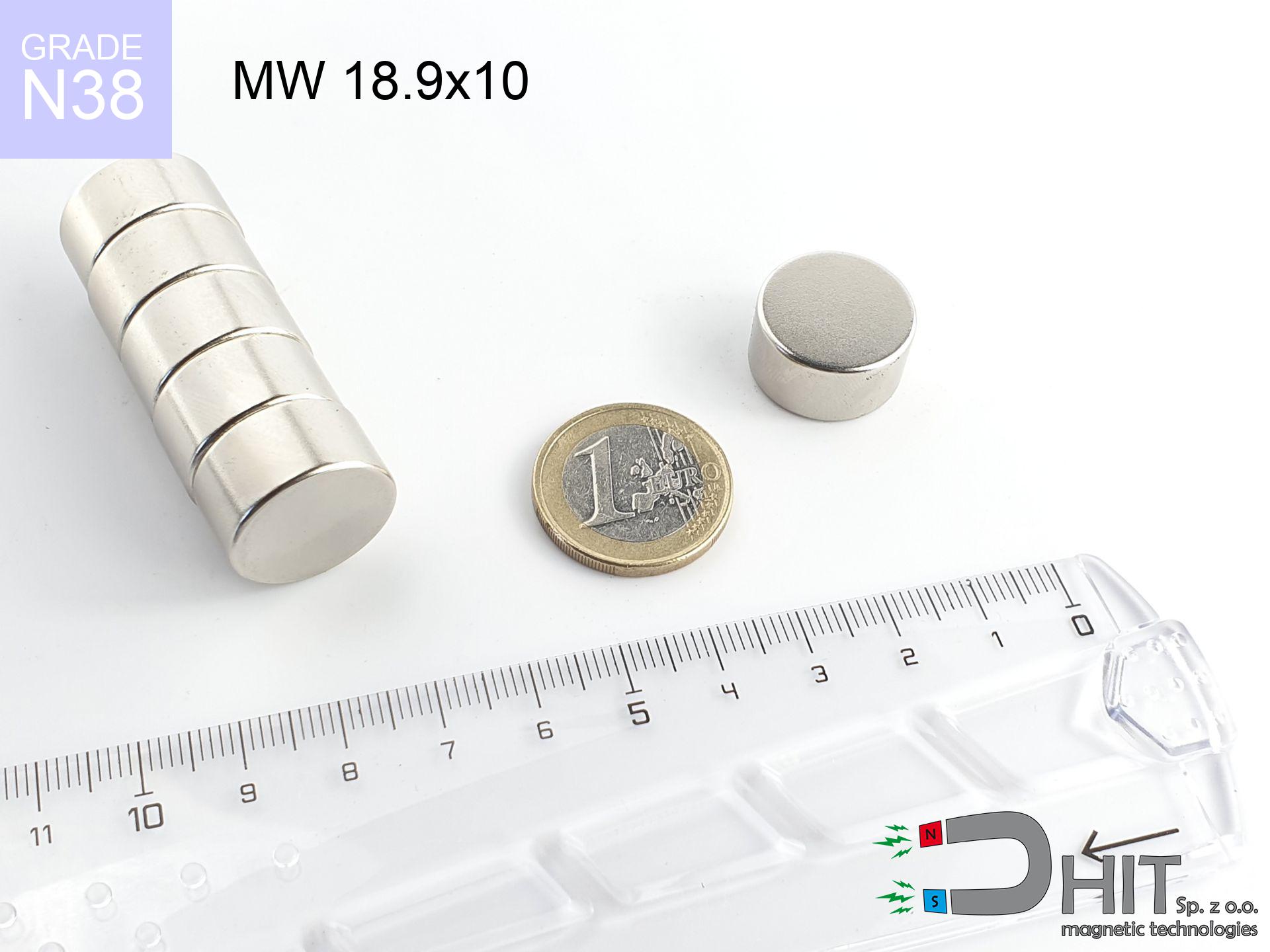
MW 18.9x10 / N38 - cylindrical magnet
cylindrical magnet
Catalog no 010036
GTIN/EAN: 5906301810353
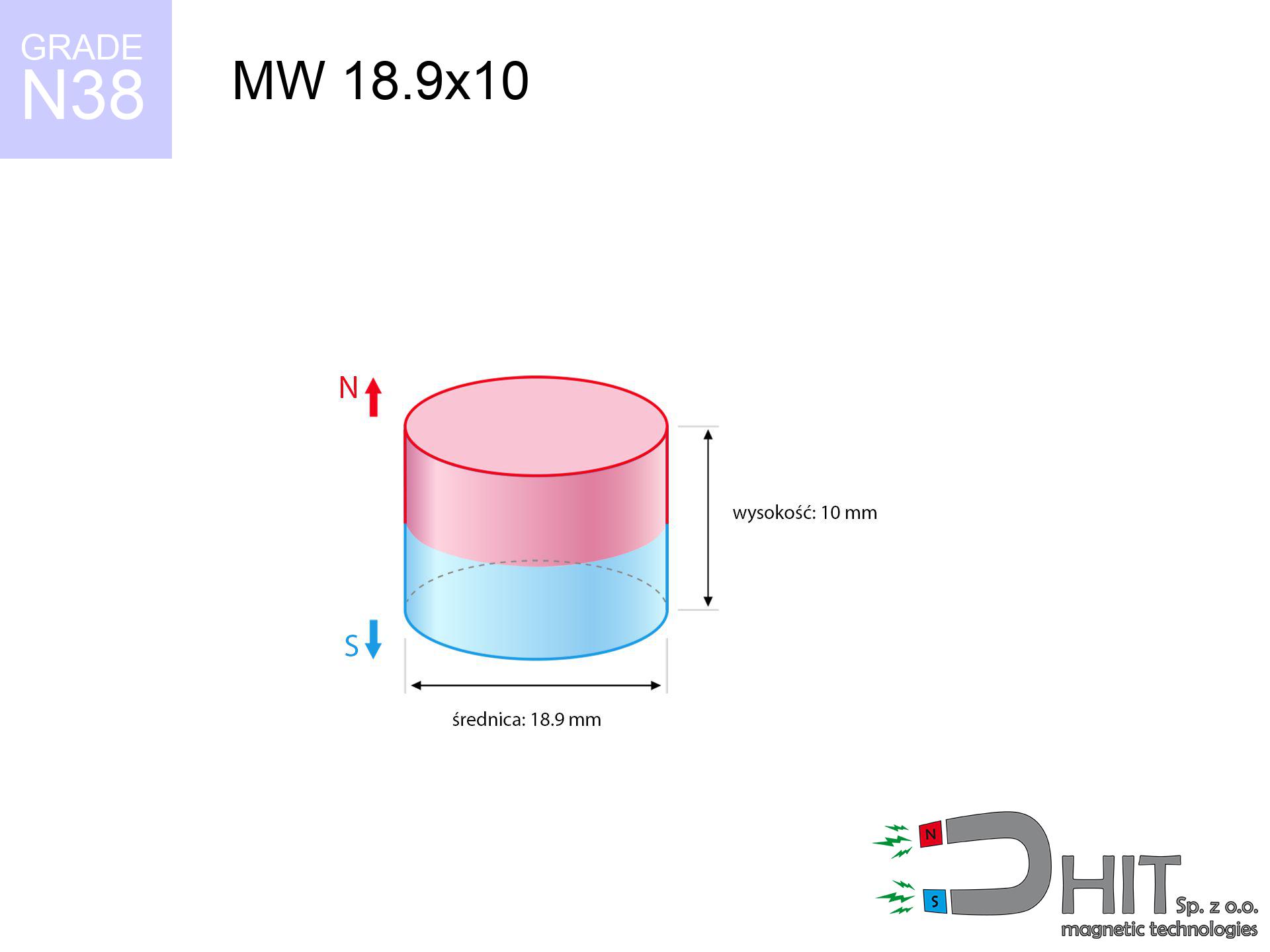
- Diameter Ø
- 18.9 mm [±0,1 mm]
- Height
- 10 mm [±0,1 mm]
- Weight
- 21.04 g
- Magnetization Direction
- → diametrical
- Coating
- [NiCuNi] Nickel
How we measure these parameters — certificates and measurements
9.00 zł net / pcs
11.07 zł with VAT (23% VAT) / pcs
bulk discounts:
Need more?Frequently asked questions
Where can I buy strong cylindrical neodymium magnets?
Can a small cylindrical magnet provide a strong grip for precise workshop work?
Which cylindrical magnet can work at a higher temperature?
Call us now
+48 888 99 98 98
alternatively let us know using
contact form
the contact section.
Specifications and structure of a neodymium magnet can be estimated using our
power calculator.
Order by 14:00 and we’ll ship today!
Technical - MW 18.9x10 / N38 - cylindrical magnet
Specification / characteristics - MW 18.9x10 / N38 - cylindrical magnet
| properties | values |
|---|---|
| Cat. no. | 010036 |
| GTIN/EAN | 5906301810353 |
| Production/Distribution | Dhit sp. z o.o. |
| Country of origin | Poland / China / Germany |
| Customs code | 85059029 |
| Diameter Ø | 18.9 mm [±0,1 mm] |
| Height | 10 mm [±0,1 mm] |
| Weight | 21.04 g |
| Magnetization Direction | → diametrical |
| Load capacity ~ ? | 11.68 kg / 114.54 N |
| Magnetic Induction ~ ? | 450.35 mT / 4503 Gs |
| Coating | [NiCuNi] Nickel |
| Manufacturing Tolerance | ±0.1 mm |
Magnetic properties of material N38
| properties | values | units |
|---|---|---|
| Remanence Br ? | 12.2-12.6 | kGs |
| Remanence Br ? | 1220-1260 | mT |
| Coercivity bHc ? | 10.8-11.5 | kOe |
| Coercivity bHc ? | 860-915 | kA/m |
| Intrinsic coercivity iHc | ≥ 12 | kOe |
| Intrinsic coercivity iHc | ≥ 955 | kA/m |
| Energy product BHmax ? | 36-38 | BH max MGOe |
| Energy product BHmax ? | 287-303 | BH max KJ/m |
| Maximum working temperature ? | ≤ 80 | °C |
Physical properties of sintered neodymium magnets Nd2Fe14B at 20°C
| properties | values | units |
|---|---|---|
| Vickers hardness | ≥550 | Hv |
| Density | ≥7.4 | g/cm3 |
| Curie Temperature TC | 310 | °C |
| Curie Temperature TF | 590 | °F |
| Specific resistance | 150 | μΩ⋅cm |
| Bending strength | 250 | MPa |
| Compressive strength | 1000~1100 | MPa |
| Thermal expansion parallel (∥) to orientation (M) | (3-4) x 10-6 | °C-1 |
| Thermal expansion perpendicular (⊥) to orientation (M) | -(1-3) x 10-6 | °C-1 |
| Young's modulus | 1.7 x 10⁴ | kg/mm² |
Engineering analysis of the product - report
Presented data represent the direct effect of a engineering calculation. Results are based on models for the class Nd2Fe14B. Real-world conditions may deviate from the simulation results. Please consider these data as a supplementary guide for designers.
Table 1: Static force (force vs gap) - characteristics
MW 18.9x10 / N38
| Distance (mm) | Induction (Gauss) / mT | Pull Force (kg/lbs/g/N) | Risk Status |
|---|---|---|---|
| 0 mm |
4502 Gs
450.2 mT
|
11.68 kg / 25.75 lbs
11680.0 g / 114.6 N
|
critical level |
| 1 mm |
4050 Gs
405.0 mT
|
9.46 kg / 20.85 lbs
9455.2 g / 92.8 N
|
strong |
| 2 mm |
3587 Gs
358.7 mT
|
7.42 kg / 16.35 lbs
7416.3 g / 72.8 N
|
strong |
| 3 mm |
3139 Gs
313.9 mT
|
5.68 kg / 12.52 lbs
5678.8 g / 55.7 N
|
strong |
| 5 mm |
2346 Gs
234.6 mT
|
3.17 kg / 6.99 lbs
3172.5 g / 31.1 N
|
strong |
| 10 mm |
1100 Gs
110.0 mT
|
0.70 kg / 1.54 lbs
696.7 g / 6.8 N
|
low risk |
| 15 mm |
554 Gs
55.4 mT
|
0.18 kg / 0.39 lbs
176.7 g / 1.7 N
|
low risk |
| 20 mm |
308 Gs
30.8 mT
|
0.05 kg / 0.12 lbs
54.6 g / 0.5 N
|
low risk |
| 30 mm |
120 Gs
12.0 mT
|
0.01 kg / 0.02 lbs
8.3 g / 0.1 N
|
low risk |
| 50 mm |
32 Gs
3.2 mT
|
0.00 kg / 0.00 lbs
0.6 g / 0.0 N
|
low risk |
Table 2: Vertical load (wall)
MW 18.9x10 / N38
| Distance (mm) | Friction coefficient | Pull Force (kg/lbs/g/N) |
|---|---|---|
| 0 mm | Stal (~0.2) |
2.34 kg / 5.15 lbs
2336.0 g / 22.9 N
|
| 1 mm | Stal (~0.2) |
1.89 kg / 4.17 lbs
1892.0 g / 18.6 N
|
| 2 mm | Stal (~0.2) |
1.48 kg / 3.27 lbs
1484.0 g / 14.6 N
|
| 3 mm | Stal (~0.2) |
1.14 kg / 2.50 lbs
1136.0 g / 11.1 N
|
| 5 mm | Stal (~0.2) |
0.63 kg / 1.40 lbs
634.0 g / 6.2 N
|
| 10 mm | Stal (~0.2) |
0.14 kg / 0.31 lbs
140.0 g / 1.4 N
|
| 15 mm | Stal (~0.2) |
0.04 kg / 0.08 lbs
36.0 g / 0.4 N
|
| 20 mm | Stal (~0.2) |
0.01 kg / 0.02 lbs
10.0 g / 0.1 N
|
| 30 mm | Stal (~0.2) |
0.00 kg / 0.00 lbs
2.0 g / 0.0 N
|
| 50 mm | Stal (~0.2) |
0.00 kg / 0.00 lbs
0.0 g / 0.0 N
|
Table 3: Vertical assembly (shearing) - vertical pull
MW 18.9x10 / N38
| Surface type | Friction coefficient / % Mocy | Max load (kg/lbs/g/N) |
|---|---|---|
| Raw steel |
µ = 0.3
30% Nominalnej Siły
|
3.50 kg / 7.72 lbs
3504.0 g / 34.4 N
|
| Painted steel (standard) |
µ = 0.2
20% Nominalnej Siły
|
2.34 kg / 5.15 lbs
2336.0 g / 22.9 N
|
| Oily/slippery steel |
µ = 0.1
10% Nominalnej Siły
|
1.17 kg / 2.57 lbs
1168.0 g / 11.5 N
|
| Magnet with anti-slip rubber |
µ = 0.5
50% Nominalnej Siły
|
5.84 kg / 12.87 lbs
5840.0 g / 57.3 N
|
Table 4: Steel thickness (saturation) - power losses
MW 18.9x10 / N38
| Steel thickness (mm) | % power | Real pull force (kg/lbs/g/N) |
|---|---|---|
| 0.5 mm |
|
0.58 kg / 1.29 lbs
584.0 g / 5.7 N
|
| 1 mm |
|
1.46 kg / 3.22 lbs
1460.0 g / 14.3 N
|
| 2 mm |
|
2.92 kg / 6.44 lbs
2920.0 g / 28.6 N
|
| 3 mm |
|
4.38 kg / 9.66 lbs
4380.0 g / 43.0 N
|
| 5 mm |
|
7.30 kg / 16.09 lbs
7300.0 g / 71.6 N
|
| 10 mm |
|
11.68 kg / 25.75 lbs
11680.0 g / 114.6 N
|
| 11 mm |
|
11.68 kg / 25.75 lbs
11680.0 g / 114.6 N
|
| 12 mm |
|
11.68 kg / 25.75 lbs
11680.0 g / 114.6 N
|
Table 5: Thermal resistance (material behavior) - thermal limit
MW 18.9x10 / N38
| Ambient temp. (°C) | Power loss | Remaining pull (kg/lbs/g/N) | Status |
|---|---|---|---|
| 20 °C | 0.0% |
11.68 kg / 25.75 lbs
11680.0 g / 114.6 N
|
OK |
| 40 °C | -2.2% |
11.42 kg / 25.18 lbs
11423.0 g / 112.1 N
|
OK |
| 60 °C | -4.4% |
11.17 kg / 24.62 lbs
11166.1 g / 109.5 N
|
OK |
| 80 °C | -6.6% |
10.91 kg / 24.05 lbs
10909.1 g / 107.0 N
|
|
| 100 °C | -28.8% |
8.32 kg / 18.33 lbs
8316.2 g / 81.6 N
|
Table 6: Magnet-Magnet interaction (attraction) - field collision
MW 18.9x10 / N38
| Gap (mm) | Attraction (kg/lbs) (N-S) | Lateral Force (kg/lbs/g/N) | Repulsion (kg/lbs) (N-N) |
|---|---|---|---|
| 0 mm |
35.05 kg / 77.28 lbs
5 600 Gs
|
5.26 kg / 11.59 lbs
5258 g / 51.6 N
|
N/A |
| 1 mm |
31.70 kg / 69.88 lbs
8 562 Gs
|
4.75 kg / 10.48 lbs
4754 g / 46.6 N
|
28.53 kg / 62.89 lbs
~0 Gs
|
| 2 mm |
28.38 kg / 62.56 lbs
8 101 Gs
|
4.26 kg / 9.38 lbs
4256 g / 41.8 N
|
25.54 kg / 56.30 lbs
~0 Gs
|
| 3 mm |
25.22 kg / 55.59 lbs
7 636 Gs
|
3.78 kg / 8.34 lbs
3782 g / 37.1 N
|
22.69 kg / 50.03 lbs
~0 Gs
|
| 5 mm |
19.53 kg / 43.05 lbs
6 720 Gs
|
2.93 kg / 6.46 lbs
2929 g / 28.7 N
|
17.57 kg / 38.75 lbs
~0 Gs
|
| 10 mm |
9.52 kg / 20.99 lbs
4 692 Gs
|
1.43 kg / 3.15 lbs
1428 g / 14.0 N
|
8.57 kg / 18.89 lbs
~0 Gs
|
| 20 mm |
2.09 kg / 4.61 lbs
2 199 Gs
|
0.31 kg / 0.69 lbs
314 g / 3.1 N
|
1.88 kg / 4.15 lbs
~0 Gs
|
| 50 mm |
0.06 kg / 0.13 lbs
372 Gs
|
0.01 kg / 0.02 lbs
9 g / 0.1 N
|
0.05 kg / 0.12 lbs
~0 Gs
|
| 60 mm |
0.03 kg / 0.06 lbs
241 Gs
|
0.00 kg / 0.01 lbs
4 g / 0.0 N
|
0.02 kg / 0.05 lbs
~0 Gs
|
| 70 mm |
0.01 kg / 0.03 lbs
164 Gs
|
0.00 kg / 0.00 lbs
2 g / 0.0 N
|
0.01 kg / 0.02 lbs
~0 Gs
|
| 80 mm |
0.01 kg / 0.01 lbs
116 Gs
|
0.00 kg / 0.00 lbs
1 g / 0.0 N
|
0.00 kg / 0.00 lbs
~0 Gs
|
| 90 mm |
0.00 kg / 0.01 lbs
86 Gs
|
0.00 kg / 0.00 lbs
0 g / 0.0 N
|
0.00 kg / 0.00 lbs
~0 Gs
|
| 100 mm |
0.00 kg / 0.00 lbs
65 Gs
|
0.00 kg / 0.00 lbs
0 g / 0.0 N
|
0.00 kg / 0.00 lbs
~0 Gs
|
Table 7: Safety (HSE) (implants) - precautionary measures
MW 18.9x10 / N38
| Object / Device | Limit (Gauss) / mT | Safe distance |
|---|---|---|
| Pacemaker | 5 Gs (0.5 mT) | 10.0 cm |
| Hearing aid | 10 Gs (1.0 mT) | 8.0 cm |
| Mechanical watch | 20 Gs (2.0 mT) | 6.0 cm |
| Mobile device | 40 Gs (4.0 mT) | 5.0 cm |
| Remote | 50 Gs (5.0 mT) | 4.5 cm |
| Payment card | 400 Gs (40.0 mT) | 2.0 cm |
| HDD hard drive | 600 Gs (60.0 mT) | 1.5 cm |
Table 8: Dynamics (cracking risk) - collision effects
MW 18.9x10 / N38
| Start from (mm) | Speed (km/h) | Energy (J) | Predicted outcome |
|---|---|---|---|
| 10 mm |
22.61 km/h
(6.28 m/s)
|
0.41 J | |
| 30 mm |
23.29 km/h
(6.47 m/s)
|
0.44 J | |
| 50 mm |
23.31 km/h
(6.47 m/s)
|
0.44 J | |
| 100 mm |
23.31 km/h
(6.48 m/s)
|
0.44 J |
Table 9: Anti-corrosion coating durability
MW 18.9x10 / N38
| Technical parameter | Value / Description |
|---|---|
| Coating type | [NiCuNi] Nickel |
| Layer structure | Nickel - Copper - Nickel |
| Layer thickness | 10-20 µm |
| Salt spray test (SST) ? | 24 h |
| Recommended environment | Indoors only (dry) |
Table 10: Electrical data (Flux)
MW 18.9x10 / N38
| Parameter | Value | SI Unit / Description |
|---|---|---|
| Magnetic Flux | 12 775 Mx | 127.7 µWb |
| Pc Coefficient | 0.61 | High (Stable) |
Table 11: Physics of underwater searching
MW 18.9x10 / N38
| Environment | Effective steel pull | Effect |
|---|---|---|
| Air (land) | 11.68 kg | Standard |
| Water (riverbed) |
13.37 kg
(+1.69 kg buoyancy gain)
|
+14.5% |
1. Sliding resistance
*Warning: On a vertical wall, the magnet retains just a fraction of its nominal pull.
2. Plate thickness effect
*Thin metal sheet (e.g. computer case) drastically limits the holding force.
3. Heat tolerance
N38: the maximum material working temperature is 80°C. Permitted conditions also depend on the shape and magnetic circuit.
4. Demagnetization curve and operating point (B-H)
chart generated for the permeance coefficient Pc (Permeance Coefficient) = 0.61
This simulation demonstrates the magnetic stability of the selected magnet under specific geometric conditions. The solid red line represents the demagnetization curve (material potential), while the dashed blue line is the load line based on the magnet's geometry. The Pc (Permeance Coefficient), also known as the load line slope, is a dimensionless value that describes the relationship between the magnet's shape and its magnetic stability. The intersection of these two lines (the black dot) is the operating point — it determines the actual magnetic flux density generated by the magnet in this specific configuration. A higher Pc value means the magnet is more 'slender' (tall relative to its area), resulting in a higher operating point and better resistance to irreversible demagnetization caused by external fields or temperature. A value of 0.42 is relatively low (typical for flat magnets), meaning the operating point is closer to the 'knee' of the curve — caution is advised when operating at temperatures near the maximum limit to avoid strength loss.
Chemical composition
| iron (Fe) | 64% – 68% |
| neodymium (Nd) | 29% – 32% |
| boron (B) | 1.1% – 1.2% |
| dysprosium (Dy) | 0.5% – 2.0% |
| coating (Ni-Cu-Ni) | < 0.05% |
Sustainability
| recyclability (EoL) | 100% |
| recycled raw materials | ~10% (pre-cons) |
| carbon footprint | low / zredukowany |
| waste code (EWC) | 16 02 16 |
Check out also products
![UMGW 36x18x8 [M8] GW / N38 - magnetic holder internal thread](https://cdn3.dhit.pl/graphics/products/um-36x18x8-m8-gw-foj.jpg "UMGW 36x18x8 [M8] GW / N38 - magnetic holder internal thread")

Pros as well as cons of Nd2Fe14B magnets.
Benefits
- They retain magnetic properties for nearly 10 years – the drop is just ~1% (based on simulations),
- They have excellent resistance to magnetism drop as a result of external magnetic sources,
- By using a reflective coating of silver, the element presents an elegant look,
- Neodymium magnets create maximum magnetic induction on a small surface, which ensures high operational effectiveness,
- Neodymium magnets are characterized by extremely high magnetic induction on the magnet surface and are able to act (depending on the shape) even at a temperature of 230°C or more...
- Possibility of accurate machining and modifying to precise needs,
- Key role in electronics industry – they serve a role in magnetic memories, electric motors, medical devices, as well as complex engineering applications.
- Relatively small size with high pulling force – neodymium magnets offer strong magnetic field in compact dimensions, which makes them useful in compact constructions
Limitations
- To avoid cracks upon strong impacts, we suggest using special steel housings. Such a solution secures the magnet and simultaneously increases its durability.
- Do not exceed this material temperature limit: 80°C. Overheating may permanently weaken the magnet.
- Due to the susceptibility of magnets to corrosion in a humid environment, we suggest using waterproof magnets made of rubber, plastic or other material immune to moisture, in case of application outdoors
- We recommend a housing - magnetic mechanism, due to difficulties in realizing nuts inside the magnet and complex forms.
- Health risk to health – tiny shards of magnets are risky, if swallowed, which is particularly important in the aspect of protecting the youngest. It is also worth noting that tiny parts of these devices are able to disrupt the diagnostic process medical when they are in the body.
- Higher cost of purchase is one of the disadvantages compared to ceramic magnets, especially in budget applications
Holding force characteristics
Maximum holding power of the magnet – what contributes to it?
- with the use of a yoke made of low-carbon steel, guaranteeing full magnetic saturation
- whose transverse dimension is min. 10 mm
- with an polished contact surface
- under conditions of ideal adhesion (surface-to-surface)
- during detachment in a direction vertical to the plane
- at standard ambient temperature
What influences lifting capacity in practice
- Gap (between the magnet and the plate), since even a very small distance (e.g. 0.5 mm) results in a decrease in lifting capacity by up to 50% (this also applies to paint, rust or dirt).
- Force direction – declared lifting capacity refers to pulling vertically. When attempting to slide, the magnet holds much less (often approx. 20-30% of maximum force).
- Element thickness – for full efficiency, the steel must be adequately massive. Paper-thin metal restricts the attraction force (the magnet "punches through" it).
- Steel type – mild steel gives the best results. Higher carbon content reduce magnetic properties and holding force.
- Surface quality – the smoother and more polished the plate, the better the adhesion and stronger the hold. Roughness creates an air distance.
- Thermal conditions – neodymium magnets have a sensitivity to temperature. At higher temperatures they lose power, and in frost they can be stronger (up to a certain limit).
Holding force was tested on the plate surface of 20 mm thickness, when the force acted perpendicularly, in contrast under shearing force the lifting capacity is smaller. In addition, even a small distance between the magnet and the plate lowers the load capacity.
Safe handling of NdFeB magnets
Skin irritation risks
Studies show that the nickel plating (standard magnet coating) is a potent allergen. If you have an allergy, refrain from touching magnets with bare hands or choose encased magnets.
Conscious usage
Be careful. Neodymium magnets attract from a long distance and snap with huge force, often quicker than you can react.
Flammability
Powder generated during machining of magnets is self-igniting. Do not drill into magnets without proper cooling and knowledge.
Physical harm
Pinching hazard: The attraction force is so great that it can cause hematomas, crushing, and broken bones. Use thick gloves.
Thermal limits
Control the heat. Exposing the magnet above 80 degrees Celsius will destroy its magnetic structure and strength.
Magnetic media
Intense magnetic fields can corrupt files on payment cards, hard drives, and other magnetic media. Keep a distance of at least 10 cm.
Medical interference
Life threat: Strong magnets can turn off pacemakers and defibrillators. Stay away if you have electronic implants.
Adults only
Adult use only. Tiny parts can be swallowed, causing severe trauma. Store away from kids and pets.
Phone sensors
Be aware: rare earth magnets produce a field that disrupts precision electronics. Maintain a safe distance from your phone, tablet, and GPS.
Magnet fragility
NdFeB magnets are ceramic materials, which means they are fragile like glass. Clashing of two magnets will cause them cracking into shards.
Tabela kosztu i czasu dostawy
Płatność przed wysyłką:

GLS kurier
Przesyłka będzie u Ciebie za 2-3 dni
14.99 ZŁ

InPost Paczkomaty 24/7
Przesyłka będzie u Ciebie za 1-2 dni
12.30 ZŁ
Płatność przy odbiorze (pobranie):
GLS kurier
Przesyłka będzie u Ciebie za 1-2 dni
23.00 ZŁ