

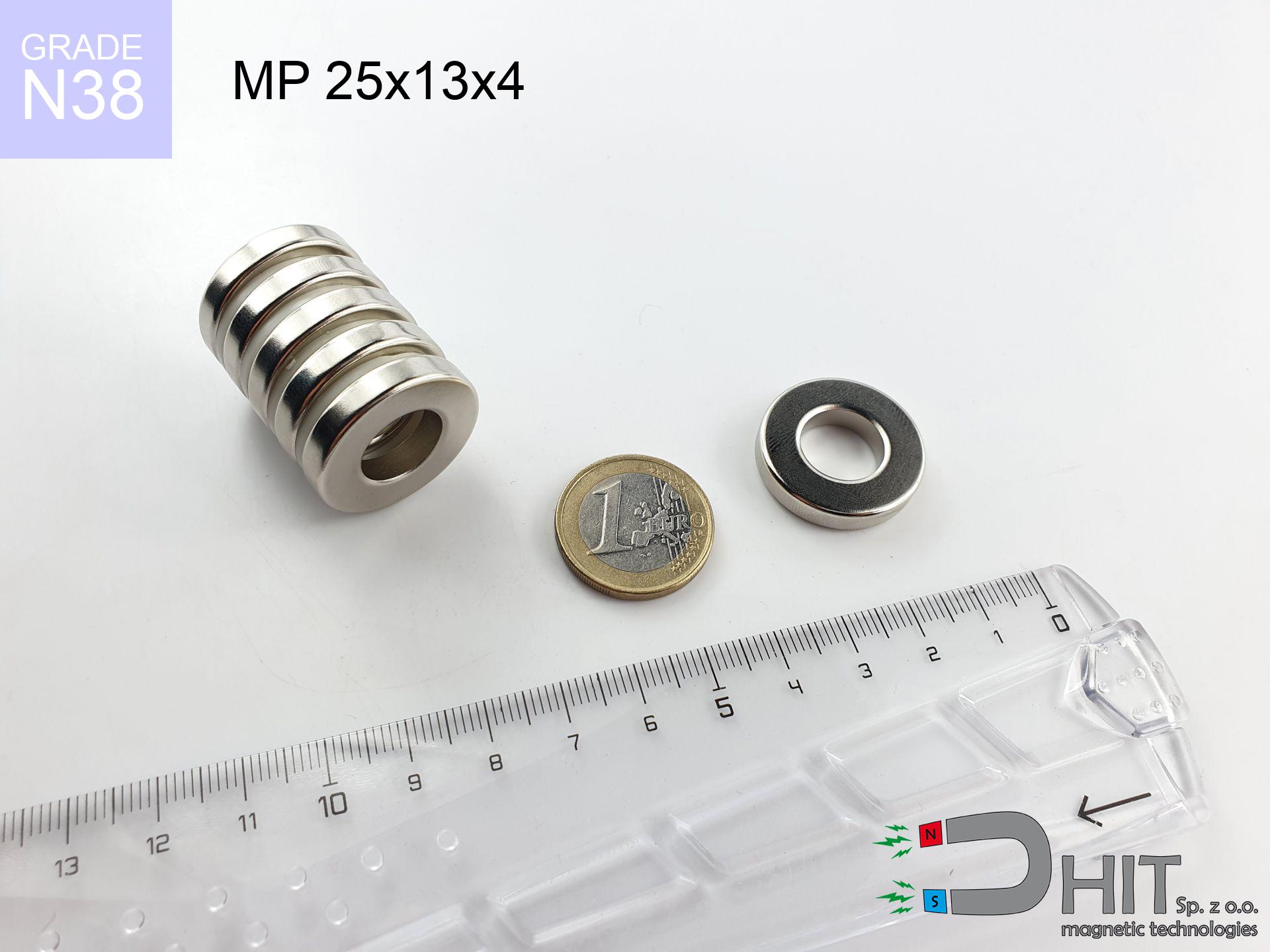
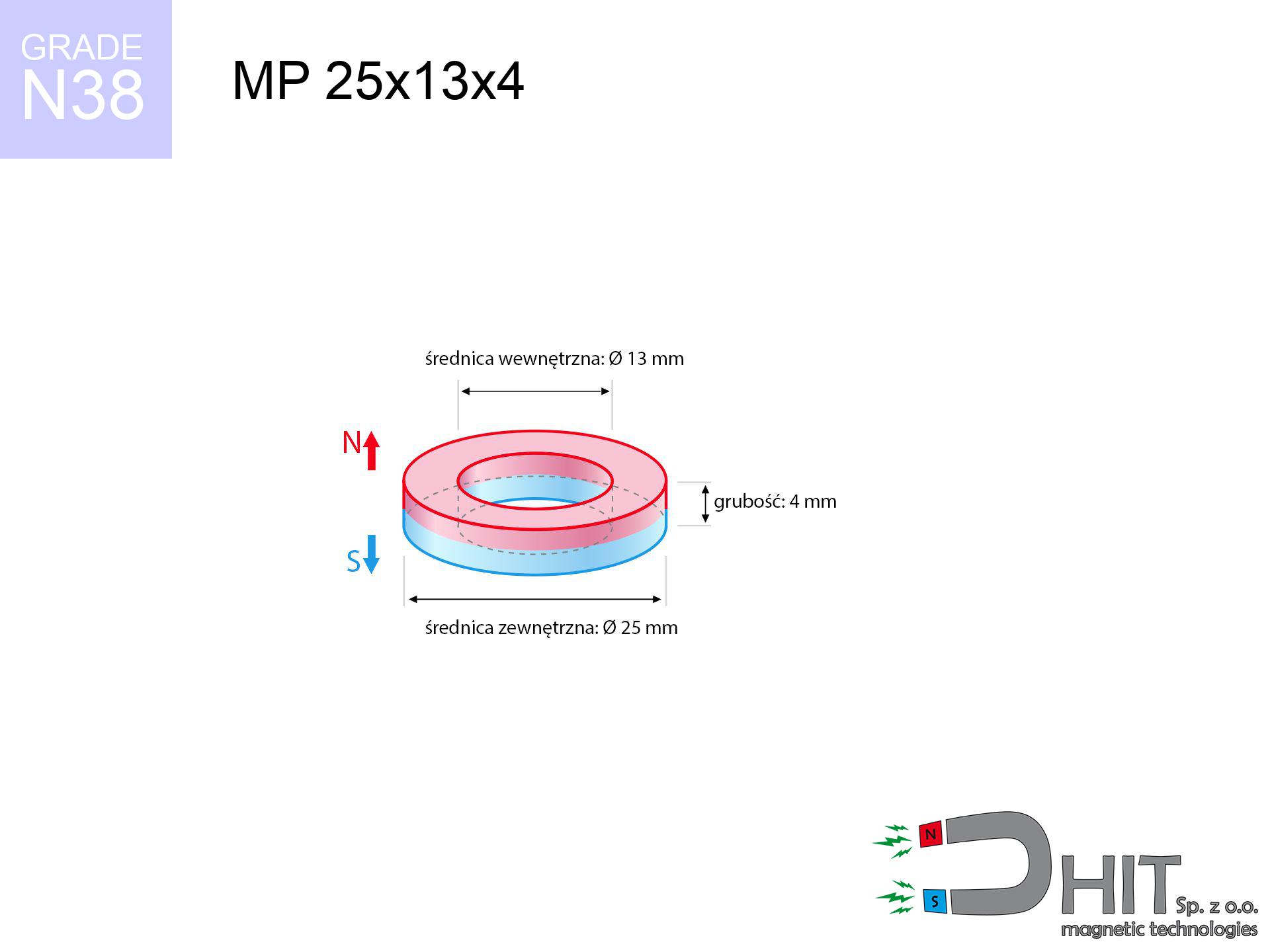
MP 25x13x4 / N38 - ring magnet
ring magnet
Catalog no 030190
GTIN/EAN: 5906301812074
- Diameter
- 25 mm [±0,1 mm]
- internal diameter Ø
- 13 mm [±0,1 mm]
- Height
- 4 mm [±0,1 mm]
- Weight
- 10.74 g
- Magnetization Direction
- ↑ axial
- Coating
- [NiCuNi] Nickel
How we measure these parameters — certificates and measurements
5.50 zł net / pcs
6.77 zł with VAT (23% VAT) / pcs
bulk discounts:
Need more?Frequently asked questions
Where can I compare prices of ring magnets for mounting in Poland?
Are ring magnets resistant to damage?
Which ring magnet is suitable for an outdoor structure?
Where can I check the available sizes of neodymium ring magnets?
Engineering report for this magnet
Full PDF analysis: pull and shear force, effect of distance, temperature and plate thickness, safety distances and the demagnetization curve.
Call us now
+48 888 99 98 98
alternatively let us know using
contact form
the contact section.
Specifications and structure of a neodymium magnet can be estimated using our
power calculator.
Order by 14:00 and we’ll ship today!
Technical data of the product - MP 25x13x4 / N38 - ring magnet
Specification / characteristics - MP 25x13x4 / N38 - ring magnet
| properties | values |
|---|---|
| Cat. no. | 030190 |
| GTIN/EAN | 5906301812074 |
| Production/Distribution | Dhit sp. z o.o. |
| Country of origin | Poland / China / Germany |
| Customs code | 85059029 |
| Diameter | 25 mm [±0,1 mm] |
| internal diameter Ø | 13 mm [±0,1 mm] |
| Height | 4 mm [±0,1 mm] |
| Weight | 10.74 g |
| Magnetization Direction | ↑ axial |
| Load capacity ~ ? | 4.14 kg / 40.57 N |
| Magnetic Induction ~ ? | 188.92 mT / 1889 Gs |
| Coating | [NiCuNi] Nickel |
| Manufacturing Tolerance | ±0.1 mm |
Magnetic properties of material N38
| properties | values | units |
|---|---|---|
| Remanence Br ? | 12.2-12.6 | kGs |
| Remanence Br ? | 1220-1260 | mT |
| Coercivity bHc ? | 10.8-11.5 | kOe |
| Coercivity bHc ? | 860-915 | kA/m |
| Intrinsic coercivity iHc | ≥ 12 | kOe |
| Intrinsic coercivity iHc | ≥ 955 | kA/m |
| Energy product BHmax ? | 36-38 | BH max MGOe |
| Energy product BHmax ? | 287-303 | BH max KJ/m |
| Maximum working temperature ? | ≤ 80 | °C |
Physical properties of sintered neodymium magnets Nd2Fe14B at 20°C
| properties | values | units |
|---|---|---|
| Vickers hardness | ≥550 | Hv |
| Density | ≥7.4 | g/cm3 |
| Curie Temperature TC | 310 | °C |
| Curie Temperature TF | 590 | °F |
| Specific resistance | 150 | μΩ⋅cm |
| Bending strength | 250 | MPa |
| Compressive strength | 1000~1100 | MPa |
| Thermal expansion parallel (∥) to orientation (M) | (3-4) x 10-6 | °C-1 |
| Thermal expansion perpendicular (⊥) to orientation (M) | -(1-3) x 10-6 | °C-1 |
| Young's modulus | 1.7 x 10⁴ | kg/mm² |
Technical simulation of the magnet - data
The following data are the direct effect of a engineering calculation. Results rely on models for the class Nd2Fe14B. Real-world parameters might slightly differ from theoretical values. Please consider these data as a preliminary roadmap during assembly planning.
Table 1: Static force (pull vs distance) - characteristics
MP 25x13x4 / N38
| Distance (mm) | Induction (Gauss) / mT | Pull Force (kg/lbs/g/N) | Risk Status |
|---|---|---|---|
| 0 mm |
5777 Gs
577.7 mT
|
4.14 kg / 9.13 lbs
4140.0 g / 40.6 N
|
warning |
| 1 mm |
5310 Gs
531.0 mT
|
3.50 kg / 7.71 lbs
3497.4 g / 34.3 N
|
warning |
| 2 mm |
4846 Gs
484.6 mT
|
2.91 kg / 6.42 lbs
2912.4 g / 28.6 N
|
warning |
| 3 mm |
4397 Gs
439.7 mT
|
2.40 kg / 5.29 lbs
2398.5 g / 23.5 N
|
warning |
| 5 mm |
3576 Gs
357.6 mT
|
1.59 kg / 3.50 lbs
1586.2 g / 15.6 N
|
weak grip |
| 10 mm |
2073 Gs
207.3 mT
|
0.53 kg / 1.17 lbs
532.9 g / 5.2 N
|
weak grip |
| 15 mm |
1231 Gs
123.1 mT
|
0.19 kg / 0.41 lbs
188.0 g / 1.8 N
|
weak grip |
| 20 mm |
773 Gs
77.3 mT
|
0.07 kg / 0.16 lbs
74.0 g / 0.7 N
|
weak grip |
| 30 mm |
356 Gs
35.6 mT
|
0.02 kg / 0.03 lbs
15.7 g / 0.2 N
|
weak grip |
| 50 mm |
115 Gs
11.5 mT
|
0.00 kg / 0.00 lbs
1.6 g / 0.0 N
|
weak grip |
Table 2: Vertical force (wall)
MP 25x13x4 / N38
| Distance (mm) | Friction coefficient | Pull Force (kg/lbs/g/N) |
|---|---|---|
| 0 mm | Raw steel (µ ≈ 0.2) |
0.83 kg / 1.83 lbs
828.0 g / 8.1 N
|
| 1 mm | Raw steel (µ ≈ 0.2) |
0.70 kg / 1.54 lbs
700.0 g / 6.9 N
|
| 2 mm | Raw steel (µ ≈ 0.2) |
0.58 kg / 1.28 lbs
582.0 g / 5.7 N
|
| 3 mm | Raw steel (µ ≈ 0.2) |
0.48 kg / 1.06 lbs
480.0 g / 4.7 N
|
| 5 mm | Raw steel (µ ≈ 0.2) |
0.32 kg / 0.70 lbs
318.0 g / 3.1 N
|
| 10 mm | Raw steel (µ ≈ 0.2) |
0.11 kg / 0.23 lbs
106.0 g / 1.0 N
|
| 15 mm | Raw steel (µ ≈ 0.2) |
0.04 kg / 0.08 lbs
38.0 g / 0.4 N
|
| 20 mm | Raw steel (µ ≈ 0.2) |
0.01 kg / 0.03 lbs
14.0 g / 0.1 N
|
| 30 mm | Raw steel (µ ≈ 0.2) |
0.00 kg / 0.01 lbs
4.0 g / 0.0 N
|
| 50 mm | Raw steel (µ ≈ 0.2) |
0.00 kg / 0.00 lbs
0.0 g / 0.0 N
|
Table 3: Vertical assembly (sliding) - vertical pull
MP 25x13x4 / N38
| Surface type | Friction coefficient / % | Max load (kg/lbs/g/N) |
|---|---|---|
| Raw steel |
µ = 0.3
30% of nominal force
|
1.24 kg / 2.74 lbs
1242.0 g / 12.2 N
|
| Painted steel (standard) |
µ = 0.2
20% of nominal force
|
0.83 kg / 1.83 lbs
828.0 g / 8.1 N
|
| Oily/slippery steel |
µ = 0.1
10% of nominal force
|
0.41 kg / 0.91 lbs
414.0 g / 4.1 N
|
| Magnet with anti-slip rubber |
µ = 0.5
50% of nominal force
|
2.07 kg / 4.56 lbs
2070.0 g / 20.3 N
|
Table 4: Material efficiency (saturation) - sheet metal selection
MP 25x13x4 / N38
| Steel thickness (mm) | % power | Real pull force (kg/lbs/g/N) |
|---|---|---|
| 0.5 mm |
|
0.41 kg / 0.91 lbs
414.0 g / 4.1 N
|
| 1 mm |
|
1.04 kg / 2.28 lbs
1035.0 g / 10.2 N
|
| 2 mm |
|
2.07 kg / 4.56 lbs
2070.0 g / 20.3 N
|
| 3 mm |
|
3.10 kg / 6.85 lbs
3105.0 g / 30.5 N
|
| 5 mm |
|
4.14 kg / 9.13 lbs
4140.0 g / 40.6 N
|
| 10 mm |
|
4.14 kg / 9.13 lbs
4140.0 g / 40.6 N
|
| 11 mm |
|
4.14 kg / 9.13 lbs
4140.0 g / 40.6 N
|
| 12 mm |
|
4.14 kg / 9.13 lbs
4140.0 g / 40.6 N
|
Table 5: Thermal stability (stability) - resistance threshold
MP 25x13x4 / N38
| Magnet temperature (°C) | Force change relative to 20°C | Remaining pull (kg/lbs/g/N) | Status |
|---|---|---|---|
| 20 °C | 0.0% |
4.14 kg / 9.13 lbs
4140.0 g / 40.6 N
|
Estimate |
| 40 °C | -4.4% |
3.96 kg / 8.73 lbs
3959.8 g / 38.8 N
|
Estimate |
| 60 °C | -8.6% |
3.78 kg / 8.34 lbs
3783.7 g / 37.1 N
|
Estimate |
| 80 °C | -12.8% |
3.61 kg / 7.96 lbs
3611.6 g / 35.4 N
|
Material limit |
| 100 °C | — | — | Out of range — no model |
Table 6: Two magnets (attraction) - forces in the system
MP 25x13x4 / N38
| Gap (mm) | Attraction (kg/lbs) (N-S) | Sliding Force (kg/lbs/g/N) | Repulsion (kg/lbs) (N-N) |
|---|---|---|---|
| 0 mm |
83.66 kg / 184.44 lbs
6 082 Gs
|
12.55 kg / 27.67 lbs
12549 g / 123.1 N
|
N/A |
| 1 mm |
77.09 kg / 169.95 lbs
11 091 Gs
|
11.56 kg / 25.49 lbs
11563 g / 113.4 N
|
69.38 kg / 152.95 lbs
~0 Gs
|
| 2 mm |
70.68 kg / 155.81 lbs
10 620 Gs
|
10.60 kg / 23.37 lbs
10601 g / 104.0 N
|
63.61 kg / 140.23 lbs
~0 Gs
|
| 3 mm |
64.59 kg / 142.40 lbs
10 153 Gs
|
9.69 kg / 21.36 lbs
9689 g / 95.0 N
|
58.13 kg / 128.16 lbs
~0 Gs
|
| 5 mm |
53.48 kg / 117.90 lbs
9 238 Gs
|
8.02 kg / 17.68 lbs
8022 g / 78.7 N
|
48.13 kg / 106.11 lbs
~0 Gs
|
| 10 mm |
32.05 kg / 70.66 lbs
7 152 Gs
|
4.81 kg / 10.60 lbs
4808 g / 47.2 N
|
28.85 kg / 63.60 lbs
~0 Gs
|
| 20 mm |
10.77 kg / 23.74 lbs
4 145 Gs
|
1.62 kg / 3.56 lbs
1615 g / 15.8 N
|
9.69 kg / 21.37 lbs
~0 Gs
|
| 50 mm |
0.66 kg / 1.45 lbs
1 024 Gs
|
0.10 kg / 0.22 lbs
99 g / 1.0 N
|
0.59 kg / 1.30 lbs
~0 Gs
|
| 60 mm |
0.32 kg / 0.70 lbs
712 Gs
|
0.05 kg / 0.10 lbs
48 g / 0.5 N
|
0.29 kg / 0.63 lbs
~0 Gs
|
| 70 mm |
0.17 kg / 0.36 lbs
514 Gs
|
0.02 kg / 0.05 lbs
25 g / 0.2 N
|
0.15 kg / 0.33 lbs
~0 Gs
|
| 80 mm |
0.09 kg / 0.20 lbs
383 Gs
|
0.01 kg / 0.03 lbs
14 g / 0.1 N
|
0.08 kg / 0.18 lbs
~0 Gs
|
| 90 mm |
0.05 kg / 0.12 lbs
293 Gs
|
0.01 kg / 0.02 lbs
8 g / 0.1 N
|
0.05 kg / 0.11 lbs
~0 Gs
|
| 100 mm |
0.03 kg / 0.07 lbs
230 Gs
|
0.00 kg / 0.01 lbs
5 g / 0.0 N
|
0.03 kg / 0.07 lbs
~0 Gs
|
Table 7: Axial field levels — not safety zones
MP 25x13x4 / N38
| Field level (Gs) | mT | Model distance (cm) |
|---|---|---|
| < 5 Gs | < 0.5 mT | 17.0 cm |
| < 10 Gs | < 1.0 mT | 13.5 cm |
| < 20 Gs | < 2.0 mT | 10.5 cm |
| < 40 Gs | < 4.0 mT | 8.0 cm |
| < 50 Gs | < 5.0 mT | 7.5 cm |
| < 400 Gs | < 40.0 mT | 3.0 cm |
| < 600 Gs | < 60.0 mT | 2.5 cm |
Table 8: Collisions (kinetic energy) - warning
MP 25x13x4 / N38
| Start from (mm) | Speed (km/h) | Energy (J) | Predicted outcome |
|---|---|---|---|
| 10 mm |
20.89 km/h
(5.80 m/s)
|
0.18 J | |
| 30 mm |
22.33 km/h
(6.20 m/s)
|
0.21 J | |
| 50 mm |
22.39 km/h
(6.22 m/s)
|
0.21 J | |
| 100 mm |
22.40 km/h
(6.22 m/s)
|
0.21 J |
Table 9: Surface protection spec
MP 25x13x4 / N38
| Technical parameter | Value / Description |
|---|---|
| Coating type | [NiCuNi] Nickel |
| Layer structure | Nickel - Copper - Nickel |
| Layer thickness | 10-20 µm |
| Salt spray test (SST) ? | 24 h |
| Recommended environment | Indoors only (dry) |
Table 10: Electrical data (Pc)
MP 25x13x4 / N38
| Parameter | Value | SI Unit / Description |
|---|---|---|
| Magnetic Flux | 24 861 Mx | 248.6 µWb |
| Pc Coefficient | 1.02 | High (Stable) |
Table 11: Submerged application
MP 25x13x4 / N38
| Environment | Effective steel pull | Effect |
|---|---|---|
| Air (land) | 4.14 kg | Standard |
| Water (riverbed) |
4.74 kg
(+0.60 kg buoyancy gain)
|
+14.5% |
1. Wall mount (shear)
*Note: On a vertical wall, the magnet retains merely approx. 20-30% of its max power.
2. Plate thickness effect
*Thin steel (e.g. 0.5mm PC case) severely weakens the holding force.
3. Temperature resistance
N38: the maximum material working temperature is 80°C. Permitted conditions also depend on the shape and magnetic circuit.
4. Demagnetization curve and operating point (B-H)
chart generated for the permeance coefficient Pc (Permeance Coefficient) = 1.02
The chart above illustrates the magnetic characteristics of the material within the second quadrant of the hysteresis loop. The solid red line represents the demagnetization curve (material potential), while the dashed blue line is the load line based on the magnet's geometry. The Pc (Permeance Coefficient), also known as the load line slope, is a dimensionless value that describes the relationship between the magnet's shape and its magnetic stability. The intersection of these two lines (the black dot) is the operating point — it determines the actual magnetic flux density generated by the magnet in this specific configuration. A higher Pc value means the magnet is more 'slender' (tall relative to its area), resulting in a higher operating point and better resistance to irreversible demagnetization caused by external fields or temperature. A value of 0.42 is relatively low (typical for flat magnets), meaning the operating point is closer to the 'knee' of the curve — caution is advised when operating at temperatures near the maximum limit to avoid strength loss.
Chemical composition
| iron (Fe) | 64% – 68% |
| neodymium (Nd) | 29% – 32% |
| boron (B) | 1.1% – 1.2% |
| dysprosium (Dy) | 0.5% – 2.0% |
| coating (Ni-Cu-Ni) | < 0.05% |
Ecology and recycling (GPSR)
| recyclability (EoL) | 100% |
| recycled raw materials | ~10% (pre-cons) |
| carbon footprint | low / zredukowany |
| waste code (EWC) | 16 02 16 |
See also products

Pros and cons of rare earth magnets.
Pros
- Their strength remains stable, and after around ten years it decreases only by ~1% (according to research),
- Magnets effectively protect themselves against demagnetization caused by external fields,
- Thanks to the glossy finish, the surface of nickel, gold-plated, or silver gives an clean appearance,
- Magnets are distinguished by exceptionally strong magnetic induction on the surface,
- Through (adequate) combination of ingredients, they can achieve high thermal strength, allowing for action at temperatures approaching 230°C and above...
- Possibility of individual machining and adjusting to complex requirements,
- Wide application in advanced technology sectors – they are utilized in data components, electric drive systems, diagnostic systems, as well as other advanced devices.
- Thanks to concentrated force, small magnets offer high operating force, in miniature format,
Cons
- To avoid cracks upon strong impacts, we suggest using special steel holders. Such a solution protects the magnet and simultaneously improves its durability.
- Do not exceed this material temperature limit: 80°C. Overheating may permanently weaken the magnet.
- Due to the susceptibility of magnets to corrosion in a humid environment, we suggest using waterproof magnets made of rubber, plastic or other material resistant to moisture, in case of application outdoors
- Limited possibility of producing threads in the magnet and complex shapes - preferred is casing - magnet mounting.
- Possible danger resulting from small fragments of magnets pose a threat, if swallowed, which is particularly important in the aspect of protecting the youngest. Additionally, small components of these devices can be problematic in diagnostics medical when they are in the body.
- With mass production the cost of neodymium magnets can be a barrier,
Pull force analysis
Maximum magnetic pulling force – what affects it?
- on a plate made of mild steel, optimally conducting the magnetic flux
- possessing a thickness of min. 10 mm to ensure full flux closure
- with a surface cleaned and smooth
- without the slightest clearance between the magnet and steel
- during pulling in a direction vertical to the plane
- at conditions approx. 20°C
What influences lifting capacity in practice
- Gap (betwixt the magnet and the plate), since even a microscopic distance (e.g. 0.5 mm) leads to a decrease in lifting capacity by up to 50% (this also applies to varnish, corrosion or dirt).
- Force direction – declared lifting capacity refers to pulling vertically. When applying parallel force, the magnet exhibits much less (typically approx. 20-30% of nominal force).
- Wall thickness – the thinner the sheet, the weaker the hold. Part of the magnetic field passes through the material instead of converting into lifting capacity.
- Material composition – different alloys attracts identically. Alloy additives weaken the interaction with the magnet.
- Plate texture – smooth surfaces guarantee perfect abutment, which improves field saturation. Rough surfaces reduce efficiency.
- Thermal environment – temperature increase results in weakening of force. It is worth remembering the maximum operating temperature for a given model.
Lifting capacity was assessed using a steel plate with a smooth surface of optimal thickness (min. 20 mm), under perpendicular pulling force, in contrast under parallel forces the load capacity is reduced by as much as 75%. Moreover, even a minimal clearance between the magnet and the plate lowers the load capacity.
Safety rules for work with NdFeB magnets
This is not a toy
Absolutely keep magnets away from children. Choking hazard is high, and the effects of magnets connecting inside the body are tragic.
Sensitization to coating
It is widely known that the nickel plating (standard magnet coating) is a strong allergen. For allergy sufferers, prevent touching magnets with bare hands or opt for versions in plastic housing.
Dust explosion hazard
Dust generated during cutting of magnets is flammable. Avoid drilling into magnets unless you are an expert.
ICD Warning
For implant holders: Powerful magnets affect medical devices. Keep at least 30 cm distance or ask another person to work with the magnets.
Serious injuries
Big blocks can smash fingers in a fraction of a second. Under no circumstances put your hand betwixt two attracting surfaces.
Impact on smartphones
A strong magnetic field interferes with the functioning of magnetometers in phones and GPS navigation. Keep magnets near a smartphone to prevent damaging the sensors.
Do not overheat magnets
Do not exceed the maximum operating temperature stated in the specifications of the particular product. The limit depends on the material, geometry and operating arrangement; there is no single threshold for all neodymium magnets. Overheating can permanently weaken a magnet.
Safe operation
Handle magnets consciously. Their powerful strength can surprise even professionals. Plan your moves and respect their force.
Threat to electronics
Do not bring magnets near a wallet, computer, or screen. The magnetism can permanently damage these devices and wipe information from cards.
Beware of splinters
Neodymium magnets are ceramic materials, meaning they are very brittle. Impact of two magnets leads to them shattering into small pieces.
Tabela kosztu i czasu dostawy
Płatność przed wysyłką:

GLS kurier
Przesyłka będzie u Ciebie za 2-3 dni
14.99 ZŁ

InPost Paczkomaty 24/7
Przesyłka będzie u Ciebie za 1-2 dni
12.30 ZŁ
Płatność przy odbiorze (pobranie):
GLS kurier
Przesyłka będzie u Ciebie za 1-2 dni
23.00 ZŁ