


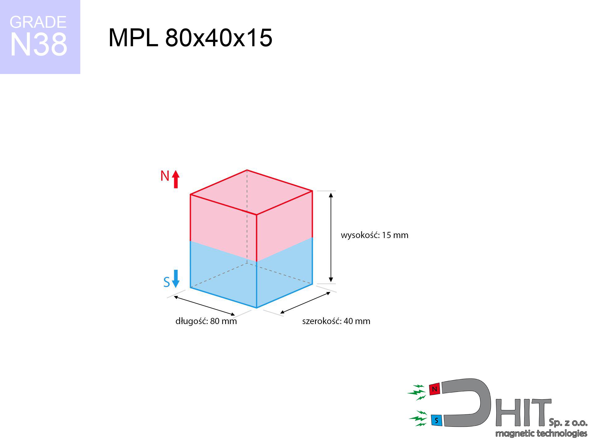
MPL 80x40x15 / N38 - lamellar magnet
lamellar magnet
Catalog no 020177
GTIN/EAN: 5906301811831
- length
- 80 mm [±0,1 mm]
- Width
- 40 mm [±0,1 mm]
- Height
- 15 mm [±0,1 mm]
- Weight
- 360 g
- Magnetization Direction
- ↑ axial
- Coating
- [NiCuNi] Nickel
How we measure these parameters — certificates and measurements
113.45 zł net / pcs
139.54 zł with VAT (23% VAT) / pcs
bulk discounts:
Need more?Frequently asked questions
What pull rating should I choose for a workshop block magnet?
Are block neodymium magnets available in more durable versions?
How should I choose block magnets for mounting a structure?
Engineering report for this magnet
Full PDF analysis: pull and shear force, effect of distance, temperature and plate thickness, safety distances and the demagnetization curve.
Call us now
+48 888 99 98 98
alternatively let us know using
contact form
the contact section.
Specifications and structure of a neodymium magnet can be estimated using our
power calculator.
Order by 14:00 and we’ll ship today!
Technical data - MPL 80x40x15 / N38 - lamellar magnet
Specification / characteristics - MPL 80x40x15 / N38 - lamellar magnet
| properties | values |
|---|---|
| Cat. no. | 020177 |
| GTIN/EAN | 5906301811831 |
| Production/Distribution | Dhit sp. z o.o. |
| Country of origin | Poland / China / Germany |
| Customs code | 85059029 |
| length | 80 mm [±0,1 mm] |
| Width | 40 mm [±0,1 mm] |
| Height | 15 mm [±0,1 mm] |
| Weight | 360 g |
| Magnetization Direction | ↑ axial |
| Load capacity ~ ? | 73.57 kg / 721.75 N |
| Magnetic Induction ~ ? | 285.78 mT / 2858 Gs |
| Coating | [NiCuNi] Nickel |
| Manufacturing Tolerance | ±0.1 mm |
Magnetic properties of material N38
| properties | values | units |
|---|---|---|
| Remanence Br ? | 12.2-12.6 | kGs |
| Remanence Br ? | 1220-1260 | mT |
| Coercivity bHc ? | 10.8-11.5 | kOe |
| Coercivity bHc ? | 860-915 | kA/m |
| Intrinsic coercivity iHc | ≥ 12 | kOe |
| Intrinsic coercivity iHc | ≥ 955 | kA/m |
| Energy product BHmax ? | 36-38 | BH max MGOe |
| Energy product BHmax ? | 287-303 | BH max KJ/m |
| Maximum working temperature ? | ≤ 80 | °C |
Physical properties of sintered neodymium magnets Nd2Fe14B at 20°C
| properties | values | units |
|---|---|---|
| Vickers hardness | ≥550 | Hv |
| Density | ≥7.4 | g/cm3 |
| Curie Temperature TC | 310 | °C |
| Curie Temperature TF | 590 | °F |
| Specific resistance | 150 | μΩ⋅cm |
| Bending strength | 250 | MPa |
| Compressive strength | 1000~1100 | MPa |
| Thermal expansion parallel (∥) to orientation (M) | (3-4) x 10-6 | °C-1 |
| Thermal expansion perpendicular (⊥) to orientation (M) | -(1-3) x 10-6 | °C-1 |
| Young's modulus | 1.7 x 10⁴ | kg/mm² |
Physical analysis of the product - technical parameters
These data are the outcome of a engineering simulation. Results are based on models for the material Nd2Fe14B. Real-world parameters may differ from theoretical values. Please consider these data as a supplementary guide during assembly planning.
Table 1: Static pull force (pull vs distance) - interaction chart
MPL 80x40x15 / N38
| Distance (mm) | Induction (Gauss) / mT | Pull Force (kg/lbs/g/N) | Risk Status |
|---|---|---|---|
| 0 mm |
2857 Gs
285.7 mT
|
73.57 kg / 162.19 LBS
73570.0 g / 721.7 N
|
critical level |
| 1 mm |
2778 Gs
277.8 mT
|
69.55 kg / 153.32 LBS
69546.1 g / 682.2 N
|
critical level |
| 2 mm |
2693 Gs
269.3 mT
|
65.33 kg / 144.03 LBS
65331.2 g / 640.9 N
|
critical level |
| 3 mm |
2603 Gs
260.3 mT
|
61.05 kg / 134.59 LBS
61047.5 g / 598.9 N
|
critical level |
| 5 mm |
2415 Gs
241.5 mT
|
52.56 kg / 115.87 LBS
52559.7 g / 515.6 N
|
critical level |
| 10 mm |
1943 Gs
194.3 mT
|
34.02 kg / 75.00 LBS
34021.1 g / 333.7 N
|
critical level |
| 15 mm |
1527 Gs
152.7 mT
|
21.01 kg / 46.31 LBS
21007.7 g / 206.1 N
|
critical level |
| 20 mm |
1192 Gs
119.2 mT
|
12.81 kg / 28.24 LBS
12808.1 g / 125.6 N
|
critical level |
| 30 mm |
736 Gs
73.6 mT
|
4.89 kg / 10.77 LBS
4886.6 g / 47.9 N
|
strong |
| 50 mm |
313 Gs
31.3 mT
|
0.88 kg / 1.95 LBS
884.8 g / 8.7 N
|
low risk |
Table 2: Shear force (wall)
MPL 80x40x15 / N38
| Distance (mm) | Friction coefficient | Pull Force (kg/lbs/g/N) |
|---|---|---|
| 0 mm | Raw steel (µ ≈ 0.2) |
14.71 kg / 32.44 LBS
14714.0 g / 144.3 N
|
| 1 mm | Raw steel (µ ≈ 0.2) |
13.91 kg / 30.67 LBS
13910.0 g / 136.5 N
|
| 2 mm | Raw steel (µ ≈ 0.2) |
13.07 kg / 28.81 LBS
13066.0 g / 128.2 N
|
| 3 mm | Raw steel (µ ≈ 0.2) |
12.21 kg / 26.92 LBS
12210.0 g / 119.8 N
|
| 5 mm | Raw steel (µ ≈ 0.2) |
10.51 kg / 23.17 LBS
10512.0 g / 103.1 N
|
| 10 mm | Raw steel (µ ≈ 0.2) |
6.80 kg / 15.00 LBS
6804.0 g / 66.7 N
|
| 15 mm | Raw steel (µ ≈ 0.2) |
4.20 kg / 9.26 LBS
4202.0 g / 41.2 N
|
| 20 mm | Raw steel (µ ≈ 0.2) |
2.56 kg / 5.65 LBS
2562.0 g / 25.1 N
|
| 30 mm | Raw steel (µ ≈ 0.2) |
0.98 kg / 2.16 LBS
978.0 g / 9.6 N
|
| 50 mm | Raw steel (µ ≈ 0.2) |
0.18 kg / 0.39 LBS
176.0 g / 1.7 N
|
Table 3: Wall mounting (shearing) - behavior on slippery surfaces
MPL 80x40x15 / N38
| Surface type | Friction coefficient / % | Max load (kg/lbs/g/N) |
|---|---|---|
| Raw steel |
µ = 0.3
30% of nominal force
|
22.07 kg / 48.66 LBS
22071.0 g / 216.5 N
|
| Painted steel (standard) |
µ = 0.2
20% of nominal force
|
14.71 kg / 32.44 LBS
14714.0 g / 144.3 N
|
| Oily/slippery steel |
µ = 0.1
10% of nominal force
|
7.36 kg / 16.22 LBS
7357.0 g / 72.2 N
|
| Magnet with anti-slip rubber |
µ = 0.5
50% of nominal force
|
36.79 kg / 81.10 LBS
36785.0 g / 360.9 N
|
Table 4: Material efficiency (substrate influence) - sheet metal selection
MPL 80x40x15 / N38
| Steel thickness (mm) | % power | Real pull force (kg/lbs/g/N) |
|---|---|---|
| 0.5 mm |
|
2.45 kg / 5.41 LBS
2452.3 g / 24.1 N
|
| 1 mm |
|
6.13 kg / 13.52 LBS
6130.8 g / 60.1 N
|
| 2 mm |
|
12.26 kg / 27.03 LBS
12261.7 g / 120.3 N
|
| 3 mm |
|
18.39 kg / 40.55 LBS
18392.5 g / 180.4 N
|
| 5 mm |
|
30.65 kg / 67.58 LBS
30654.2 g / 300.7 N
|
| 10 mm |
|
61.31 kg / 135.16 LBS
61308.3 g / 601.4 N
|
| 11 mm |
|
67.44 kg / 148.68 LBS
67439.2 g / 661.6 N
|
| 12 mm |
|
73.57 kg / 162.19 LBS
73570.0 g / 721.7 N
|
Table 5: Thermal stability (stability) - resistance threshold
MPL 80x40x15 / N38
| Magnet temperature (°C) | Force change relative to 20°C | Remaining pull (kg/lbs/g/N) | Status |
|---|---|---|---|
| 20 °C | 0.0% |
73.57 kg / 162.19 LBS
73570.0 g / 721.7 N
|
Estimate |
| 40 °C | -4.4% |
70.37 kg / 155.14 LBS
70368.5 g / 690.3 N
|
Estimate |
| 60 °C | -8.6% |
67.24 kg / 148.23 LBS
67238.3 g / 659.6 N
|
Estimate |
| 80 °C | -12.8% |
64.18 kg / 141.49 LBS
64179.2 g / 629.6 N
|
Material limit |
| 100 °C | — | — | Out of range — no model |
Table 6: Two magnets (attraction) - field range
MPL 80x40x15 / N38
| Gap (mm) | Attraction (kg/lbs) (N-S) | Lateral Force (kg/lbs/g/N) | Repulsion (kg/lbs) (N-N) |
|---|---|---|---|
| 0 mm |
161.08 kg / 355.13 LBS
4 384 Gs
|
24.16 kg / 53.27 LBS
24163 g / 237.0 N
|
N/A |
| 1 mm |
156.77 kg / 345.63 LBS
5 638 Gs
|
23.52 kg / 51.84 LBS
23516 g / 230.7 N
|
141.10 kg / 311.07 LBS
~0 Gs
|
| 2 mm |
152.27 kg / 335.70 LBS
5 556 Gs
|
22.84 kg / 50.36 LBS
22841 g / 224.1 N
|
137.05 kg / 302.13 LBS
~0 Gs
|
| 3 mm |
147.69 kg / 325.60 LBS
5 472 Gs
|
22.15 kg / 48.84 LBS
22153 g / 217.3 N
|
132.92 kg / 293.04 LBS
~0 Gs
|
| 5 mm |
138.36 kg / 305.04 LBS
5 297 Gs
|
20.75 kg / 45.76 LBS
20754 g / 203.6 N
|
124.53 kg / 274.53 LBS
~0 Gs
|
| 10 mm |
115.08 kg / 253.71 LBS
4 830 Gs
|
17.26 kg / 38.06 LBS
17262 g / 169.3 N
|
103.57 kg / 228.34 LBS
~0 Gs
|
| 20 mm |
74.49 kg / 164.22 LBS
3 886 Gs
|
11.17 kg / 24.63 LBS
11174 g / 109.6 N
|
67.04 kg / 147.80 LBS
~0 Gs
|
| 50 mm |
17.20 kg / 37.91 LBS
1 867 Gs
|
2.58 kg / 5.69 LBS
2580 g / 25.3 N
|
15.48 kg / 34.12 LBS
~0 Gs
|
| 60 mm |
10.70 kg / 23.59 LBS
1 473 Gs
|
1.60 kg / 3.54 LBS
1605 g / 15.7 N
|
9.63 kg / 21.23 LBS
~0 Gs
|
| 70 mm |
6.78 kg / 14.94 LBS
1 172 Gs
|
1.02 kg / 2.24 LBS
1017 g / 10.0 N
|
6.10 kg / 13.45 LBS
~0 Gs
|
| 80 mm |
4.38 kg / 9.65 LBS
942 Gs
|
0.66 kg / 1.45 LBS
657 g / 6.4 N
|
3.94 kg / 8.69 LBS
~0 Gs
|
| 90 mm |
2.89 kg / 6.36 LBS
765 Gs
|
0.43 kg / 0.95 LBS
433 g / 4.2 N
|
2.60 kg / 5.72 LBS
~0 Gs
|
| 100 mm |
1.94 kg / 4.27 LBS
627 Gs
|
0.29 kg / 0.64 LBS
291 g / 2.9 N
|
1.74 kg / 3.84 LBS
~0 Gs
|
Table 7: Axial field levels — not safety zones
MPL 80x40x15 / N38
| Field level (Gs) | mT | Model distance (cm) |
|---|---|---|
| < 5 Gs | < 0.5 mT | 26.0 cm |
| < 10 Gs | < 1.0 mT | 20.5 cm |
| < 20 Gs | < 2.0 mT | 16.0 cm |
| < 40 Gs | < 4.0 mT | 12.5 cm |
| < 50 Gs | < 5.0 mT | 11.5 cm |
| < 400 Gs | < 40.0 mT | 4.5 cm |
| < 600 Gs | < 60.0 mT | 3.5 cm |
Table 8: Dynamics (kinetic energy) - warning
MPL 80x40x15 / N38
| Start from (mm) | Speed (km/h) | Energy (J) | Predicted outcome |
|---|---|---|---|
| 10 mm |
19.36 km/h
(5.38 m/s)
|
5.20 J | |
| 30 mm |
24.22 km/h
(6.73 m/s)
|
8.15 J | |
| 50 mm |
24.87 km/h
(6.91 m/s)
|
8.59 J | |
| 100 mm |
25.05 km/h
(6.96 m/s)
|
8.72 J |
Table 9: Surface protection spec
MPL 80x40x15 / N38
| Technical parameter | Value / Description |
|---|---|
| Coating type | [NiCuNi] Nickel |
| Layer structure | Nickel - Copper - Nickel |
| Layer thickness | 10-20 µm |
| Salt spray test (SST) ? | 24 h |
| Recommended environment | Indoors only (dry) |
Table 10: Electrical data (Flux)
MPL 80x40x15 / N38
| Parameter | Value | SI Unit / Description |
|---|---|---|
| Magnetic Flux | 94 833 Mx | 948.3 µWb |
| Pc Coefficient | 0.33 | Low (Flat) |
Table 11: Submerged application
MPL 80x40x15 / N38
| Environment | Effective steel pull | Effect |
|---|---|---|
| Air (land) | 73.57 kg | Standard |
| Water (riverbed) |
84.24 kg
(+10.67 kg buoyancy gain)
|
+14.5% |
1. Vertical hold
*Note: On a vertical wall, the magnet holds just a fraction of its max power.
2. Plate thickness effect
*Thin metal sheet (e.g. computer case) significantly reduces the holding force.
3. Heat tolerance
N38: the maximum material working temperature is 80°C. Permitted conditions also depend on the shape and magnetic circuit.
4. Demagnetization curve and operating point (B-H)
chart generated for the permeance coefficient Pc (Permeance Coefficient) = 0.33
This simulation demonstrates the magnetic stability of the selected magnet under specific geometric conditions. The solid red line represents the demagnetization curve (material potential), while the dashed blue line is the load line based on the magnet's geometry. The Pc (Permeance Coefficient), also known as the load line slope, is a dimensionless value that describes the relationship between the magnet's shape and its magnetic stability. The intersection of these two lines (the black dot) is the operating point — it determines the actual magnetic flux density generated by the magnet in this specific configuration. A higher Pc value means the magnet is more 'slender' (tall relative to its area), resulting in a higher operating point and better resistance to irreversible demagnetization caused by external fields or temperature. A value of 0.42 is relatively low (typical for flat magnets), meaning the operating point is closer to the 'knee' of the curve — caution is advised when operating at temperatures near the maximum limit to avoid strength loss.
Chemical composition
| iron (Fe) | 64% – 68% |
| neodymium (Nd) | 29% – 32% |
| boron (B) | 1.1% – 1.2% |
| dysprosium (Dy) | 0.5% – 2.0% |
| coating (Ni-Cu-Ni) | < 0.05% |
Sustainability
| recyclability (EoL) | 100% |
| recycled raw materials | ~10% (pre-cons) |
| carbon footprint | low / zredukowany |
| waste code (EWC) | 16 02 16 |
Other offers

Pros as well as cons of neodymium magnets.
Pros
- They virtually do not lose strength, because even after ten years the performance loss is only ~1% (in laboratory conditions),
- They do not lose their magnetic properties even under strong external field,
- By applying a lustrous layer of silver, the element has an proper look,
- Magnetic induction on the surface of the magnet is strong,
- Made from properly selected components, these magnets show impressive resistance to high heat, enabling them to function (depending on their form) at temperatures up to 230°C and above...
- Thanks to versatility in constructing and the ability to customize to client solutions,
- Significant place in electronics industry – they are commonly used in hard drives, drive modules, medical devices, as well as industrial machines.
- Relatively small size with high pulling force – neodymium magnets offer strong magnetic field in small dimensions, which makes them useful in compact constructions
Disadvantages
- To avoid cracks upon strong impacts, we recommend using special steel holders. Such a solution protects the magnet and simultaneously improves its durability.
- Do not exceed this material temperature limit: 80°C. Overheating may permanently weaken the magnet.
- Magnets exposed to a humid environment can corrode. Therefore during using outdoors, we recommend using water-impermeable magnets made of rubber, plastic or other material protecting against moisture
- Limited possibility of making threads in the magnet and complex shapes - recommended is casing - mounting mechanism.
- Possible danger to health – tiny shards of magnets pose a threat, in case of ingestion, which gains importance in the context of child safety. Additionally, tiny parts of these magnets can disrupt the diagnostic process medical in case of swallowing.
- With large orders the cost of neodymium magnets can be a barrier,
Holding force characteristics
Best holding force of the magnet in ideal parameters – what it depends on?
- using a base made of low-carbon steel, serving as a circuit closing element
- whose transverse dimension equals approx. 10 mm
- with a plane free of scratches
- with total lack of distance (no paint)
- for force acting at a right angle (in the magnet axis)
- in stable room temperature
Key elements affecting lifting force
- Distance – the presence of foreign body (rust, dirt, air) interrupts the magnetic circuit, which lowers power rapidly (even by 50% at 0.5 mm).
- Pull-off angle – remember that the magnet holds strongest perpendicularly. Under shear forces, the holding force drops drastically, often to levels of 20-30% of the maximum value.
- Base massiveness – too thin steel does not accept the full field, causing part of the power to be escaped to the other side.
- Steel grade – the best choice is high-permeability steel. Stainless steels may have worse magnetic properties.
- Surface quality – the more even the surface, the better the adhesion and higher the lifting capacity. Roughness acts like micro-gaps.
- Thermal factor – hot environment reduces pulling force. Too high temperature can permanently damage the magnet.
Lifting capacity was determined with the use of a steel plate with a smooth surface of optimal thickness (min. 20 mm), under perpendicular pulling force, in contrast under shearing force the holding force is lower. Moreover, even a small distance between the magnet and the plate lowers the lifting capacity.
H&S for magnets
Danger to pacemakers
Warning for patients: Strong magnetic fields affect electronics. Keep at least 30 cm distance or request help to work with the magnets.
Handling guide
Handle with care. Neodymium magnets act from a distance and connect with massive power, often quicker than you can react.
Flammability
Dust generated during cutting of magnets is self-igniting. Avoid drilling into magnets unless you are an expert.
Do not give to children
NdFeB magnets are not toys. Eating multiple magnets can lead to them connecting inside the digestive tract, which poses a critical condition and necessitates immediate surgery.
Impact on smartphones
Navigation devices and mobile phones are extremely susceptible to magnetism. Direct contact with a powerful NdFeB magnet can permanently damage the internal compass in your phone.
Physical harm
Pinching hazard: The pulling power is so immense that it can cause blood blisters, crushing, and broken bones. Use thick gloves.
Shattering risk
Despite the nickel coating, neodymium is delicate and cannot withstand shocks. Avoid impacts, as the magnet may shatter into sharp, dangerous pieces.
Threat to electronics
Avoid bringing magnets close to a purse, laptop, or screen. The magnetic field can irreversibly ruin these devices and erase data from cards.
Skin irritation risks
A percentage of the population experience a sensitization to nickel, which is the standard coating for neodymium magnets. Frequent touching can result in dermatitis. It is best to wear safety gloves.
Thermal limits
Do not exceed the maximum operating temperature stated in the specifications of the particular product. The limit depends on the material, geometry and operating arrangement; there is no single threshold for all neodymium magnets. Overheating can permanently weaken a magnet.
Tabela kosztu i czasu dostawy
Płatność przed wysyłką:

GLS kurier
Przesyłka będzie u Ciebie za 2-3 dni
14.99 ZŁ

InPost Paczkomaty 24/7
Przesyłka będzie u Ciebie za 1-2 dni
12.30 ZŁ
Płatność przy odbiorze (pobranie):
GLS kurier
Przesyłka będzie u Ciebie za 1-2 dni
23.00 ZŁ