

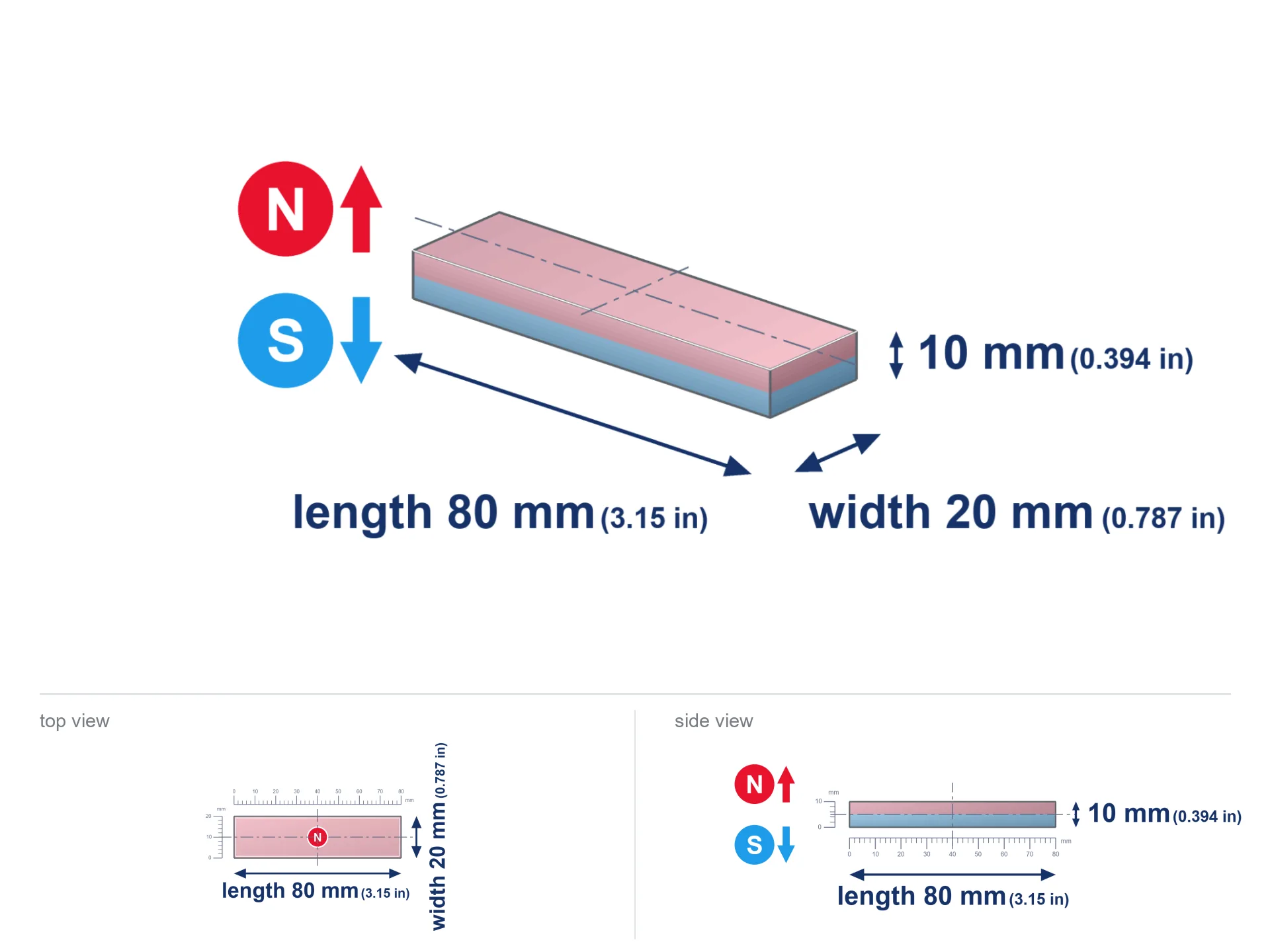
MPL 80x20x10 / N38 - lamellar magnet
lamellar magnet
Catalog no 020586
GTIN/EAN: 5906301815792
- length
- 80 mm [±0,1 mm]
- Width
- 20 mm [±0,1 mm]
- Height
- 10 mm [±0,1 mm]
- Weight
- 120 g
- Magnetization Direction
- ↑ axial
- Coating
- [NiCuNi] Nickel
How we measure these parameters — certificates and measurements
44.65 zł net / pcs
54.92 zł with VAT (23% VAT) / pcs
bulk discounts:
Need more?Frequently asked questions
What pull rating should I choose for a workshop block magnet?
Are block neodymium magnets available in more durable versions?
How should I choose block magnets for mounting a structure?
Engineering report for this magnet
Full PDF analysis: pull and shear force, effect of distance, temperature and plate thickness, safety distances and the demagnetization curve.
Call us now
+48 888 99 98 98
alternatively let us know using
contact form
the contact section.
Specifications and structure of a neodymium magnet can be estimated using our
power calculator.
Order by 14:00 and we’ll ship today!
Technical data - MPL 80x20x10 / N38 - lamellar magnet
Specification / characteristics - MPL 80x20x10 / N38 - lamellar magnet
| properties | values |
|---|---|
| Cat. no. | 020586 |
| GTIN/EAN | 5906301815792 |
| Distributor | Dhit sp. z o.o. |
| Country of origin | Poland / China / Germany |
| Customs code | 85059029 |
| length | 80 mm [±0,1 mm] |
| Width | 20 mm [±0,1 mm] |
| Height | 10 mm [±0,1 mm] |
| Weight | 120 g |
| Magnetization Direction | ↑ axial |
| Load capacity ~ ? | 47.40 kg / 464.84 N |
| Magnetic Induction ~ ? | 321.49 mT / 3215 Gs |
| Coating | [NiCuNi] Nickel |
| Manufacturing Tolerance | ±0.1 mm |
Magnetic properties of material N38
| properties | values | units |
|---|---|---|
| Remanence Br ? | 12.2-12.6 | kGs |
| Remanence Br ? | 1220-1260 | mT |
| Coercivity bHc ? | 10.8-11.5 | kOe |
| Coercivity bHc ? | 860-915 | kA/m |
| Intrinsic coercivity iHc | ≥ 12 | kOe |
| Intrinsic coercivity iHc | ≥ 955 | kA/m |
| Energy product BHmax ? | 36-38 | BH max MGOe |
| Energy product BHmax ? | 287-303 | BH max KJ/m |
| Maximum working temperature ? | ≤ 80 | °C |
Physical properties of sintered neodymium magnets Nd2Fe14B at 20°C
| properties | values | units |
|---|---|---|
| Vickers hardness | ≥550 | Hv |
| Density | ≥7.4 | g/cm3 |
| Curie Temperature TC | 310 | °C |
| Curie Temperature TF | 590 | °F |
| Specific resistance | 150 | μΩ⋅cm |
| Bending strength | 250 | MPa |
| Compressive strength | 1000~1100 | MPa |
| Thermal expansion parallel (∥) to orientation (M) | (3-4) x 10-6 | °C-1 |
| Thermal expansion perpendicular (⊥) to orientation (M) | -(1-3) x 10-6 | °C-1 |
| Young's modulus | 1.7 x 10⁴ | kg/mm² |
Physical simulation of the assembly - data
These information constitute the result of a mathematical calculation. Values are based on algorithms for the class Nd2Fe14B. Operational conditions may differ. Please consider these calculations as a reference point during assembly planning.
Table 1: Static force (force vs gap) - characteristics
MPL 80x20x10 / N38
| Distance (mm) | Induction (Gauss) / mT | Pull Force (kg/lbs/g/N) | Risk Status |
|---|---|---|---|
| 0 mm |
3214 Gs
321.4 mT
|
47.40 kg / 104.50 lbs
47400.0 g / 465.0 N
|
crushing |
| 1 mm |
3009 Gs
300.9 mT
|
41.54 kg / 91.58 lbs
41538.8 g / 407.5 N
|
crushing |
| 2 mm |
2791 Gs
279.1 mT
|
35.75 kg / 78.81 lbs
35746.4 g / 350.7 N
|
crushing |
| 3 mm |
2572 Gs
257.2 mT
|
30.35 kg / 66.91 lbs
30348.6 g / 297.7 N
|
crushing |
| 5 mm |
2154 Gs
215.4 mT
|
21.29 kg / 46.95 lbs
21294.4 g / 208.9 N
|
crushing |
| 10 mm |
1360 Gs
136.0 mT
|
8.48 kg / 18.70 lbs
8480.9 g / 83.2 N
|
medium risk |
| 15 mm |
891 Gs
89.1 mT
|
3.64 kg / 8.03 lbs
3642.4 g / 35.7 N
|
medium risk |
| 20 mm |
615 Gs
61.5 mT
|
1.73 kg / 3.82 lbs
1734.1 g / 17.0 N
|
safe |
| 30 mm |
329 Gs
32.9 mT
|
0.50 kg / 1.10 lbs
497.3 g / 4.9 N
|
safe |
| 50 mm |
124 Gs
12.4 mT
|
0.07 kg / 0.16 lbs
70.9 g / 0.7 N
|
safe |
Table 2: Sliding hold (wall)
MPL 80x20x10 / N38
| Distance (mm) | Friction coefficient | Pull Force (kg/lbs/g/N) |
|---|---|---|
| 0 mm | Raw steel (µ ≈ 0.2) |
9.48 kg / 20.90 lbs
9480.0 g / 93.0 N
|
| 1 mm | Raw steel (µ ≈ 0.2) |
8.31 kg / 18.32 lbs
8308.0 g / 81.5 N
|
| 2 mm | Raw steel (µ ≈ 0.2) |
7.15 kg / 15.76 lbs
7150.0 g / 70.1 N
|
| 3 mm | Raw steel (µ ≈ 0.2) |
6.07 kg / 13.38 lbs
6070.0 g / 59.5 N
|
| 5 mm | Raw steel (µ ≈ 0.2) |
4.26 kg / 9.39 lbs
4258.0 g / 41.8 N
|
| 10 mm | Raw steel (µ ≈ 0.2) |
1.70 kg / 3.74 lbs
1696.0 g / 16.6 N
|
| 15 mm | Raw steel (µ ≈ 0.2) |
0.73 kg / 1.60 lbs
728.0 g / 7.1 N
|
| 20 mm | Raw steel (µ ≈ 0.2) |
0.35 kg / 0.76 lbs
346.0 g / 3.4 N
|
| 30 mm | Raw steel (µ ≈ 0.2) |
0.10 kg / 0.22 lbs
100.0 g / 1.0 N
|
| 50 mm | Raw steel (µ ≈ 0.2) |
0.01 kg / 0.03 lbs
14.0 g / 0.1 N
|
Table 3: Vertical assembly (sliding) - vertical pull
MPL 80x20x10 / N38
| Surface type | Friction coefficient / % | Max load (kg/lbs/g/N) |
|---|---|---|
| Raw steel |
µ = 0.3
30% of nominal force
|
14.22 kg / 31.35 lbs
14220.0 g / 139.5 N
|
| Painted steel (standard) |
µ = 0.2
20% of nominal force
|
9.48 kg / 20.90 lbs
9480.0 g / 93.0 N
|
| Oily/slippery steel |
µ = 0.1
10% of nominal force
|
4.74 kg / 10.45 lbs
4740.0 g / 46.5 N
|
| Magnet with anti-slip rubber |
µ = 0.5
50% of nominal force
|
23.70 kg / 52.25 lbs
23700.0 g / 232.5 N
|
Table 4: Material efficiency (substrate influence) - power losses
MPL 80x20x10 / N38
| Steel thickness (mm) | % power | Real pull force (kg/lbs/g/N) |
|---|---|---|
| 0.5 mm |
|
2.37 kg / 5.22 lbs
2370.0 g / 23.2 N
|
| 1 mm |
|
5.93 kg / 13.06 lbs
5925.0 g / 58.1 N
|
| 2 mm |
|
11.85 kg / 26.12 lbs
11850.0 g / 116.2 N
|
| 3 mm |
|
17.78 kg / 39.19 lbs
17775.0 g / 174.4 N
|
| 5 mm |
|
29.63 kg / 65.31 lbs
29625.0 g / 290.6 N
|
| 10 mm |
|
47.40 kg / 104.50 lbs
47400.0 g / 465.0 N
|
| 11 mm |
|
47.40 kg / 104.50 lbs
47400.0 g / 465.0 N
|
| 12 mm |
|
47.40 kg / 104.50 lbs
47400.0 g / 465.0 N
|
Table 5: Working in heat (stability) - power drop
MPL 80x20x10 / N38
| Magnet temperature (°C) | Force change relative to 20°C | Remaining pull (kg/lbs/g/N) | Status |
|---|---|---|---|
| 20 °C | 0.0% |
47.40 kg / 104.50 lbs
47400.0 g / 465.0 N
|
Estimate |
| 40 °C | -4.4% |
45.34 kg / 99.95 lbs
45337.3 g / 444.8 N
|
Estimate |
| 60 °C | -8.6% |
43.32 kg / 95.51 lbs
43320.6 g / 425.0 N
|
Estimate |
| 80 °C | -12.8% |
41.35 kg / 91.16 lbs
41349.7 g / 405.6 N
|
Material limit |
| 100 °C | — | — | Out of range — no model |
Table 6: Magnet-Magnet interaction (attraction) - field range
MPL 80x20x10 / N38
| Gap (mm) | Attraction (kg/lbs) (N-S) | Shear Force (kg/lbs/g/N) | Repulsion (kg/lbs) (N-N) |
|---|---|---|---|
| 0 mm |
101.90 kg / 224.66 lbs
4 573 Gs
|
15.29 kg / 33.70 lbs
15286 g / 150.0 N
|
N/A |
| 1 mm |
95.68 kg / 210.93 lbs
6 229 Gs
|
14.35 kg / 31.64 lbs
14352 g / 140.8 N
|
86.11 kg / 189.84 lbs
~0 Gs
|
| 2 mm |
89.30 kg / 196.88 lbs
6 018 Gs
|
13.40 kg / 29.53 lbs
13395 g / 131.4 N
|
80.37 kg / 177.19 lbs
~0 Gs
|
| 3 mm |
83.00 kg / 182.99 lbs
5 802 Gs
|
12.45 kg / 27.45 lbs
12450 g / 122.1 N
|
74.70 kg / 164.69 lbs
~0 Gs
|
| 5 mm |
70.91 kg / 156.34 lbs
5 363 Gs
|
10.64 kg / 23.45 lbs
10637 g / 104.4 N
|
63.82 kg / 140.71 lbs
~0 Gs
|
| 10 mm |
45.78 kg / 100.93 lbs
4 309 Gs
|
6.87 kg / 15.14 lbs
6867 g / 67.4 N
|
41.20 kg / 90.84 lbs
~0 Gs
|
| 20 mm |
18.23 kg / 40.20 lbs
2 719 Gs
|
2.73 kg / 6.03 lbs
2735 g / 26.8 N
|
16.41 kg / 36.18 lbs
~0 Gs
|
| 50 mm |
1.93 kg / 4.26 lbs
885 Gs
|
0.29 kg / 0.64 lbs
290 g / 2.8 N
|
1.74 kg / 3.83 lbs
~0 Gs
|
| 60 mm |
1.07 kg / 2.36 lbs
658 Gs
|
0.16 kg / 0.35 lbs
160 g / 1.6 N
|
0.96 kg / 2.12 lbs
~0 Gs
|
| 70 mm |
0.62 kg / 1.37 lbs
502 Gs
|
0.09 kg / 0.21 lbs
93 g / 0.9 N
|
0.56 kg / 1.23 lbs
~0 Gs
|
| 80 mm |
0.38 kg / 0.83 lbs
391 Gs
|
0.06 kg / 0.12 lbs
57 g / 0.6 N
|
0.34 kg / 0.75 lbs
~0 Gs
|
| 90 mm |
0.24 kg / 0.52 lbs
310 Gs
|
0.04 kg / 0.08 lbs
35 g / 0.3 N
|
0.21 kg / 0.47 lbs
~0 Gs
|
| 100 mm |
0.15 kg / 0.34 lbs
249 Gs
|
0.02 kg / 0.05 lbs
23 g / 0.2 N
|
0.14 kg / 0.30 lbs
~0 Gs
|
Table 7: Axial field levels — not safety zones
MPL 80x20x10 / N38
| Field level (Gs) | mT | Model distance (cm) |
|---|---|---|
| < 5 Gs | < 0.5 mT | 18.0 cm |
| < 10 Gs | < 1.0 mT | 14.0 cm |
| < 20 Gs | < 2.0 mT | 11.0 cm |
| < 40 Gs | < 4.0 mT | 8.5 cm |
| < 50 Gs | < 5.0 mT | 7.5 cm |
| < 400 Gs | < 40.0 mT | 3.0 cm |
| < 600 Gs | < 60.0 mT | 2.5 cm |
Table 8: Impact energy (kinetic energy) - collision effects
MPL 80x20x10 / N38
| Start from (mm) | Speed (km/h) | Energy (J) | Predicted outcome |
|---|---|---|---|
| 10 mm |
22.41 km/h
(6.22 m/s)
|
2.32 J | |
| 30 mm |
24.69 km/h
(6.86 m/s)
|
2.82 J | |
| 50 mm |
24.87 km/h
(6.91 m/s)
|
2.86 J | |
| 100 mm |
24.91 km/h
(6.92 m/s)
|
2.87 J |
Table 9: Surface protection spec
MPL 80x20x10 / N38
| Technical parameter | Value / Description |
|---|---|
| Coating type | [NiCuNi] Nickel |
| Layer structure | Nickel - Copper - Nickel |
| Layer thickness | 10-20 µm |
| Salt spray test (SST) ? | 24 h |
| Recommended environment | Indoors only (dry) |
Table 10: Electrical data (Pc)
MPL 80x20x10 / N38
| Parameter | Value | SI Unit / Description |
|---|---|---|
| Magnetic Flux | 45 676 Mx | 456.8 µWb |
| Pc Coefficient | 0.31 | Low (Flat) |
Table 11: Submerged application
MPL 80x20x10 / N38
| Environment | Effective steel pull | Effect |
|---|---|---|
| Air (land) | 47.40 kg | Standard |
| Water (riverbed) |
54.27 kg
(+6.87 kg buoyancy gain)
|
+14.5% |
1. Wall mount (shear)
*Caution: On a vertical surface, the magnet retains merely a fraction of its max power.
2. Steel saturation
*Thin steel (e.g. 0.5mm PC case) significantly weakens the holding force.
3. Power loss vs temp
N38: the maximum material working temperature is 80°C. Permitted conditions also depend on the shape and magnetic circuit.
4. Demagnetization curve and operating point (B-H)
chart generated for the permeance coefficient Pc (Permeance Coefficient) = 0.31
This simulation demonstrates the magnetic stability of the selected magnet under specific geometric conditions. The solid red line represents the demagnetization curve (material potential), while the dashed blue line is the load line based on the magnet's geometry. The Pc (Permeance Coefficient), also known as the load line slope, is a dimensionless value that describes the relationship between the magnet's shape and its magnetic stability. The intersection of these two lines (the black dot) is the operating point — it determines the actual magnetic flux density generated by the magnet in this specific configuration. A higher Pc value means the magnet is more 'slender' (tall relative to its area), resulting in a higher operating point and better resistance to irreversible demagnetization caused by external fields or temperature. A value of 0.42 is relatively low (typical for flat magnets), meaning the operating point is closer to the 'knee' of the curve — caution is advised when operating at temperatures near the maximum limit to avoid strength loss.
Chemical composition
| iron (Fe) | 64% – 68% |
| neodymium (Nd) | 29% – 32% |
| boron (B) | 1.1% – 1.2% |
| dysprosium (Dy) | 0.5% – 2.0% |
| coating (Ni-Cu-Ni) | < 0.05% |
Environmental data
| recyclability (EoL) | 100% |
| recycled raw materials | ~10% (pre-cons) |
| carbon footprint | low / zredukowany |
| waste code (EWC) | 16 02 16 |
Check out more offers

Pros and cons of rare earth magnets.
Benefits
- They have stable power, and over nearly 10 years their performance decreases symbolically – ~1% (according to theory),
- They maintain their magnetic properties even under close interference source,
- By applying a decorative coating of nickel, the element has an nice look,
- Magnetic induction on the working layer of the magnet turns out to be strong,
- Through (appropriate) combination of ingredients, they can achieve high thermal strength, allowing for functioning at temperatures reaching 230°C and above...
- Thanks to modularity in forming and the capacity to modify to individual projects,
- Wide application in high-tech industry – they are utilized in magnetic memories, brushless drives, advanced medical instruments, and industrial machines.
- Thanks to their power density, small magnets offer high operating force, with minimal size,
Cons
- At very strong impacts they can crack, therefore we recommend placing them in steel cases. A metal housing provides additional protection against damage, as well as increases the magnet's durability.
- Do not exceed this material temperature limit: 80°C. Overheating may permanently weaken the magnet.
- They oxidize in a humid environment. For use outdoors we suggest using waterproof magnets e.g. in rubber, plastic
- Due to limitations in producing threads and complicated shapes in magnets, we propose using cover - magnetic holder.
- Potential hazard to health – tiny shards of magnets can be dangerous, if swallowed, which is particularly important in the aspect of protecting the youngest. Furthermore, small elements of these magnets can be problematic in diagnostics medical in case of swallowing.
- Higher cost of purchase is one of the disadvantages compared to ceramic magnets, especially in budget applications
Pull force analysis
Best holding force of the magnet in ideal parameters – what it depends on?
- on a block made of structural steel, effectively closing the magnetic field
- with a cross-section minimum 10 mm
- with a surface perfectly flat
- under conditions of gap-free contact (metal-to-metal)
- for force applied at a right angle (pull-off, not shear)
- at temperature room level
Lifting capacity in real conditions – factors
- Distance (betwixt the magnet and the metal), as even a microscopic distance (e.g. 0.5 mm) can cause a decrease in lifting capacity by up to 50% (this also applies to varnish, rust or debris).
- Angle of force application – highest force is obtained only during perpendicular pulling. The force required to slide of the magnet along the surface is usually several times lower (approx. 1/5 of the lifting capacity).
- Metal thickness – thin material does not allow full use of the magnet. Part of the magnetic field penetrates through instead of generating force.
- Metal type – different alloys attracts identically. High carbon content weaken the attraction effect.
- Smoothness – full contact is obtained only on smooth steel. Rough texture create air cushions, reducing force.
- Thermal factor – high temperature reduces pulling force. Too high temperature can permanently demagnetize the magnet.
Holding force was tested on a smooth steel plate of 20 mm thickness, when a perpendicular force was applied, whereas under attempts to slide the magnet the load capacity is reduced by as much as fivefold. Additionally, even a small distance between the magnet and the plate reduces the holding force.
H&S for magnets
Magnet fragility
Despite the nickel coating, neodymium is brittle and not impact-resistant. Do not hit, as the magnet may shatter into sharp, dangerous pieces.
Warning for allergy sufferers
It is widely known that nickel (the usual finish) is a potent allergen. If your skin reacts to metals, avoid direct skin contact and choose coated magnets.
Danger to pacemakers
Warning for patients: Strong magnetic fields disrupt electronics. Maintain at least 30 cm distance or request help to work with the magnets.
Fire warning
Fire warning: Rare earth powder is explosive. Avoid machining magnets in home conditions as this may cause fire.
Serious injuries
Big blocks can smash fingers in a fraction of a second. Do not place your hand between two strong magnets.
Keep away from computers
Avoid bringing magnets near a wallet, computer, or screen. The magnetic field can destroy these devices and erase data from cards.
Powerful field
Before starting, check safety instructions. Uncontrolled attraction can break the magnet or injure your hand. Think ahead.
Precision electronics
GPS units and mobile phones are highly susceptible to magnetism. Close proximity with a powerful NdFeB magnet can permanently damage the internal compass in your phone.
This is not a toy
Strictly keep magnets away from children. Ingestion danger is high, and the effects of magnets connecting inside the body are life-threatening.
Power loss in heat
Do not exceed the maximum operating temperature stated in the specifications of the particular product. The limit depends on the material, geometry and operating arrangement; there is no single threshold for all neodymium magnets. Overheating can permanently weaken a magnet.
Tabela kosztu i czasu dostawy
Płatność przed wysyłką:

GLS kurier
Przesyłka będzie u Ciebie za 2-3 dni
14.99 ZŁ

InPost Paczkomaty 24/7
Przesyłka będzie u Ciebie za 1-2 dni
12.30 ZŁ
Płatność przy odbiorze (pobranie):
GLS kurier
Przesyłka będzie u Ciebie za 1-2 dni
23.00 ZŁ