


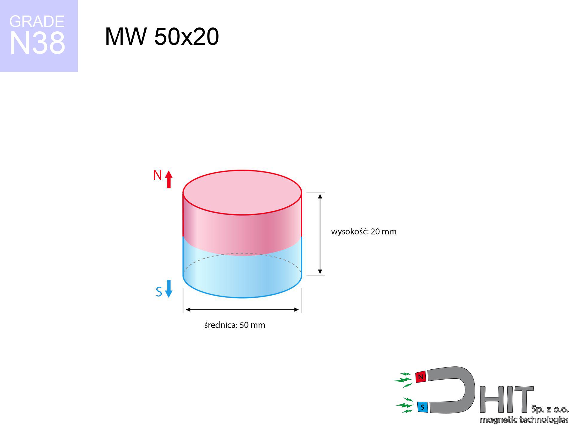
MW 50x20 / N38 - cylindrical magnet
cylindrical magnet
Catalog no 010080
GTIN/EAN: 5906301810797
- Diameter Ø
- 50 mm [±0,1 mm]
- Height
- 20 mm [±0,1 mm]
- Weight
- 294.52 g
- Magnetization Direction
- ↑ axial
- Coating
- [NiCuNi] Nickel
How we measure these parameters — certificates and measurements
86.96 zł net / pcs
106.96 zł with VAT (23% VAT) / pcs
bulk discounts:
Need more?Frequently asked questions
Where can I buy strong cylindrical neodymium magnets?
Can a small cylindrical magnet provide a strong grip for precise workshop work?
Which cylindrical magnet can work at a higher temperature?
Engineering report for this magnet
Full PDF analysis: pull and shear force, effect of distance, temperature and plate thickness, safety distances and the demagnetization curve.
Call us now
+48 888 99 98 98
alternatively let us know using
contact form
the contact section.
Specifications and structure of a neodymium magnet can be estimated using our
power calculator.
Order by 14:00 and we’ll ship today!
Physical properties - MW 50x20 / N38 - cylindrical magnet
Specification / characteristics - MW 50x20 / N38 - cylindrical magnet
| properties | values |
|---|---|
| Cat. no. | 010080 |
| GTIN/EAN | 5906301810797 |
| Production/Distribution | Dhit sp. z o.o. |
| Country of origin | Poland / China / Germany |
| Customs code | 85059029 |
| Diameter Ø | 50 mm [±0,1 mm] |
| Height | 20 mm [±0,1 mm] |
| Weight | 294.52 g |
| Magnetization Direction | ↑ axial |
| Load capacity ~ ? | 70.10 kg / 687.66 N |
| Magnetic Induction ~ ? | 387.23 mT / 3872 Gs |
| Coating | [NiCuNi] Nickel |
| Manufacturing Tolerance | ±0.1 mm |
Magnetic properties of material N38
| properties | values | units |
|---|---|---|
| Remanence Br ? | 12.2-12.6 | kGs |
| Remanence Br ? | 1220-1260 | mT |
| Coercivity bHc ? | 10.8-11.5 | kOe |
| Coercivity bHc ? | 860-915 | kA/m |
| Intrinsic coercivity iHc | ≥ 12 | kOe |
| Intrinsic coercivity iHc | ≥ 955 | kA/m |
| Energy product BHmax ? | 36-38 | BH max MGOe |
| Energy product BHmax ? | 287-303 | BH max KJ/m |
| Maximum working temperature ? | ≤ 80 | °C |
Physical properties of sintered neodymium magnets Nd2Fe14B at 20°C
| properties | values | units |
|---|---|---|
| Vickers hardness | ≥550 | Hv |
| Density | ≥7.4 | g/cm3 |
| Curie Temperature TC | 310 | °C |
| Curie Temperature TF | 590 | °F |
| Specific resistance | 150 | μΩ⋅cm |
| Bending strength | 250 | MPa |
| Compressive strength | 1000~1100 | MPa |
| Thermal expansion parallel (∥) to orientation (M) | (3-4) x 10-6 | °C-1 |
| Thermal expansion perpendicular (⊥) to orientation (M) | -(1-3) x 10-6 | °C-1 |
| Young's modulus | 1.7 x 10⁴ | kg/mm² |
Physical analysis of the magnet - report
The following information represent the direct effect of a engineering calculation. Results rely on models for the class Nd2Fe14B. Actual parameters might slightly differ from theoretical values. Use these data as a supplementary guide when designing systems.
Table 1: Static force (pull vs distance) - interaction chart
MW 50x20 / N38
| Distance (mm) | Induction (Gauss) / mT | Pull Force (kg/lbs/g/N) | Risk Status |
|---|---|---|---|
| 0 mm |
3872 Gs
387.2 mT
|
70.10 kg / 154.54 lbs
70100.0 g / 687.7 N
|
critical level |
| 1 mm |
3740 Gs
374.0 mT
|
65.41 kg / 144.20 lbs
65408.0 g / 641.7 N
|
critical level |
| 2 mm |
3601 Gs
360.1 mT
|
60.65 kg / 133.72 lbs
60652.7 g / 595.0 N
|
critical level |
| 3 mm |
3459 Gs
345.9 mT
|
55.95 kg / 123.35 lbs
55950.5 g / 548.9 N
|
critical level |
| 5 mm |
3168 Gs
316.8 mT
|
46.94 kg / 103.47 lbs
46935.3 g / 460.4 N
|
critical level |
| 10 mm |
2460 Gs
246.0 mT
|
28.31 kg / 62.40 lbs
28306.3 g / 277.7 N
|
critical level |
| 15 mm |
1855 Gs
185.5 mT
|
16.10 kg / 35.48 lbs
16095.6 g / 157.9 N
|
critical level |
| 20 mm |
1384 Gs
138.4 mT
|
8.96 kg / 19.76 lbs
8963.2 g / 87.9 N
|
medium risk |
| 30 mm |
782 Gs
78.2 mT
|
2.86 kg / 6.31 lbs
2863.1 g / 28.1 N
|
medium risk |
| 50 mm |
293 Gs
29.3 mT
|
0.40 kg / 0.89 lbs
402.4 g / 3.9 N
|
weak grip |
Table 2: Sliding load (vertical surface)
MW 50x20 / N38
| Distance (mm) | Friction coefficient | Pull Force (kg/lbs/g/N) |
|---|---|---|
| 0 mm | Stal (~0.2) |
14.02 kg / 30.91 lbs
14020.0 g / 137.5 N
|
| 1 mm | Stal (~0.2) |
13.08 kg / 28.84 lbs
13082.0 g / 128.3 N
|
| 2 mm | Stal (~0.2) |
12.13 kg / 26.74 lbs
12130.0 g / 119.0 N
|
| 3 mm | Stal (~0.2) |
11.19 kg / 24.67 lbs
11190.0 g / 109.8 N
|
| 5 mm | Stal (~0.2) |
9.39 kg / 20.70 lbs
9388.0 g / 92.1 N
|
| 10 mm | Stal (~0.2) |
5.66 kg / 12.48 lbs
5662.0 g / 55.5 N
|
| 15 mm | Stal (~0.2) |
3.22 kg / 7.10 lbs
3220.0 g / 31.6 N
|
| 20 mm | Stal (~0.2) |
1.79 kg / 3.95 lbs
1792.0 g / 17.6 N
|
| 30 mm | Stal (~0.2) |
0.57 kg / 1.26 lbs
572.0 g / 5.6 N
|
| 50 mm | Stal (~0.2) |
0.08 kg / 0.18 lbs
80.0 g / 0.8 N
|
Table 3: Vertical assembly (sliding) - behavior on slippery surfaces
MW 50x20 / N38
| Surface type | Friction coefficient / % Mocy | Max load (kg/lbs/g/N) |
|---|---|---|
| Raw steel |
µ = 0.3
30% Nominalnej Siły
|
21.03 kg / 46.36 lbs
21030.0 g / 206.3 N
|
| Painted steel (standard) |
µ = 0.2
20% Nominalnej Siły
|
14.02 kg / 30.91 lbs
14020.0 g / 137.5 N
|
| Oily/slippery steel |
µ = 0.1
10% Nominalnej Siły
|
7.01 kg / 15.45 lbs
7010.0 g / 68.8 N
|
| Magnet with anti-slip rubber |
µ = 0.5
50% Nominalnej Siły
|
35.05 kg / 77.27 lbs
35050.0 g / 343.8 N
|
Table 4: Steel thickness (saturation) - power losses
MW 50x20 / N38
| Steel thickness (mm) | % power | Real pull force (kg/lbs/g/N) |
|---|---|---|
| 0.5 mm |
|
2.34 kg / 5.15 lbs
2336.7 g / 22.9 N
|
| 1 mm |
|
5.84 kg / 12.88 lbs
5841.7 g / 57.3 N
|
| 2 mm |
|
11.68 kg / 25.76 lbs
11683.3 g / 114.6 N
|
| 3 mm |
|
17.53 kg / 38.64 lbs
17525.0 g / 171.9 N
|
| 5 mm |
|
29.21 kg / 64.39 lbs
29208.3 g / 286.5 N
|
| 10 mm |
|
58.42 kg / 128.79 lbs
58416.7 g / 573.1 N
|
| 11 mm |
|
64.26 kg / 141.67 lbs
64258.3 g / 630.4 N
|
| 12 mm |
|
70.10 kg / 154.54 lbs
70100.0 g / 687.7 N
|
Table 5: Working in heat (material behavior) - power drop
MW 50x20 / N38
| Ambient temp. (°C) | Power loss | Remaining pull (kg/lbs/g/N) | Status |
|---|---|---|---|
| 20 °C | 0.0% |
70.10 kg / 154.54 lbs
70100.0 g / 687.7 N
|
OK |
| 40 °C | -2.2% |
68.56 kg / 151.14 lbs
68557.8 g / 672.6 N
|
OK |
| 60 °C | -4.4% |
67.02 kg / 147.74 lbs
67015.6 g / 657.4 N
|
|
| 80 °C | -6.6% |
65.47 kg / 144.34 lbs
65473.4 g / 642.3 N
|
|
| 100 °C | -28.8% |
49.91 kg / 110.04 lbs
49911.2 g / 489.6 N
|
Table 6: Magnet-Magnet interaction (repulsion) - field range
MW 50x20 / N38
| Gap (mm) | Attraction (kg/lbs) (N-S) | Shear Force (kg/lbs/g/N) | Repulsion (kg/lbs) (N-N) |
|---|---|---|---|
| 0 mm |
181.46 kg / 400.06 lbs
5 255 Gs
|
27.22 kg / 60.01 lbs
27220 g / 267.0 N
|
N/A |
| 1 mm |
175.47 kg / 386.84 lbs
7 615 Gs
|
26.32 kg / 58.03 lbs
26321 g / 258.2 N
|
157.92 kg / 348.16 lbs
~0 Gs
|
| 2 mm |
169.32 kg / 373.28 lbs
7 480 Gs
|
25.40 kg / 55.99 lbs
25398 g / 249.2 N
|
152.39 kg / 335.96 lbs
~0 Gs
|
| 3 mm |
163.16 kg / 359.70 lbs
7 343 Gs
|
24.47 kg / 53.96 lbs
24474 g / 240.1 N
|
146.84 kg / 323.73 lbs
~0 Gs
|
| 5 mm |
150.90 kg / 332.67 lbs
7 061 Gs
|
22.63 kg / 49.90 lbs
22634 g / 222.0 N
|
135.81 kg / 299.40 lbs
~0 Gs
|
| 10 mm |
121.50 kg / 267.86 lbs
6 336 Gs
|
18.22 kg / 40.18 lbs
18225 g / 178.8 N
|
109.35 kg / 241.07 lbs
~0 Gs
|
| 20 mm |
73.28 kg / 161.54 lbs
4 921 Gs
|
10.99 kg / 24.23 lbs
10991 g / 107.8 N
|
65.95 kg / 145.39 lbs
~0 Gs
|
| 50 mm |
12.99 kg / 28.63 lbs
2 071 Gs
|
1.95 kg / 4.29 lbs
1948 g / 19.1 N
|
11.69 kg / 25.76 lbs
~0 Gs
|
| 60 mm |
7.41 kg / 16.34 lbs
1 565 Gs
|
1.11 kg / 2.45 lbs
1112 g / 10.9 N
|
6.67 kg / 14.71 lbs
~0 Gs
|
| 70 mm |
4.35 kg / 9.58 lbs
1 198 Gs
|
0.65 kg / 1.44 lbs
652 g / 6.4 N
|
3.91 kg / 8.62 lbs
~0 Gs
|
| 80 mm |
2.62 kg / 5.78 lbs
931 Gs
|
0.39 kg / 0.87 lbs
393 g / 3.9 N
|
2.36 kg / 5.20 lbs
~0 Gs
|
| 90 mm |
1.63 kg / 3.59 lbs
734 Gs
|
0.24 kg / 0.54 lbs
245 g / 2.4 N
|
1.47 kg / 3.23 lbs
~0 Gs
|
| 100 mm |
1.04 kg / 2.30 lbs
587 Gs
|
0.16 kg / 0.34 lbs
156 g / 1.5 N
|
0.94 kg / 2.07 lbs
~0 Gs
|
Table 7: Safety (HSE) (electronics) - precautionary measures
MW 50x20 / N38
| Object / Device | Limit (Gauss) / mT | Safe distance |
|---|---|---|
| Pacemaker | 5 Gs (0.5 mT) | 24.0 cm |
| Hearing aid | 10 Gs (1.0 mT) | 19.0 cm |
| Timepiece | 20 Gs (2.0 mT) | 15.0 cm |
| Mobile device | 40 Gs (4.0 mT) | 11.5 cm |
| Car key | 50 Gs (5.0 mT) | 10.5 cm |
| Payment card | 400 Gs (40.0 mT) | 4.5 cm |
| HDD hard drive | 600 Gs (60.0 mT) | 3.5 cm |
Table 8: Collisions (kinetic energy) - collision effects
MW 50x20 / N38
| Start from (mm) | Speed (km/h) | Energy (J) | Predicted outcome |
|---|---|---|---|
| 10 mm |
20.30 km/h
(5.64 m/s)
|
4.68 J | |
| 30 mm |
24.58 km/h
(6.83 m/s)
|
6.87 J | |
| 50 mm |
25.00 km/h
(6.95 m/s)
|
7.10 J | |
| 100 mm |
25.09 km/h
(6.97 m/s)
|
7.15 J |
Table 9: Surface protection spec
MW 50x20 / N38
| Technical parameter | Value / Description |
|---|---|
| Coating type | [NiCuNi] Nickel |
| Layer structure | Nickel - Copper - Nickel |
| Layer thickness | 10-20 µm |
| Salt spray test (SST) ? | 24 h |
| Recommended environment | Indoors only (dry) |
Table 10: Construction data (Pc)
MW 50x20 / N38
| Parameter | Value | SI Unit / Description |
|---|---|---|
| Magnetic Flux | 78 540 Mx | 785.4 µWb |
| Pc Coefficient | 0.50 | Low (Flat) |
Table 11: Submerged application
MW 50x20 / N38
| Environment | Effective steel pull | Effect |
|---|---|---|
| Air (land) | 70.10 kg | Standard |
| Water (riverbed) |
80.26 kg
(+10.16 kg buoyancy gain)
|
+14.5% |
1. Wall mount (shear)
*Note: On a vertical wall, the magnet holds just a fraction of its perpendicular strength.
2. Steel thickness impact
*Thin steel (e.g. 0.5mm PC case) severely weakens the holding force.
3. Heat tolerance
N38: the maximum material working temperature is 80°C. Permitted conditions also depend on the shape and magnetic circuit.
4. Demagnetization curve and operating point (B-H)
chart generated for the permeance coefficient Pc (Permeance Coefficient) = 0.50
The chart above illustrates the magnetic characteristics of the material within the second quadrant of the hysteresis loop. The solid red line represents the demagnetization curve (material potential), while the dashed blue line is the load line based on the magnet's geometry. The Pc (Permeance Coefficient), also known as the load line slope, is a dimensionless value that describes the relationship between the magnet's shape and its magnetic stability. The intersection of these two lines (the black dot) is the operating point — it determines the actual magnetic flux density generated by the magnet in this specific configuration. A higher Pc value means the magnet is more 'slender' (tall relative to its area), resulting in a higher operating point and better resistance to irreversible demagnetization caused by external fields or temperature. A value of 0.42 is relatively low (typical for flat magnets), meaning the operating point is closer to the 'knee' of the curve — caution is advised when operating at temperatures near the maximum limit to avoid strength loss.
Chemical composition
| iron (Fe) | 64% – 68% |
| neodymium (Nd) | 29% – 32% |
| boron (B) | 1.1% – 1.2% |
| dysprosium (Dy) | 0.5% – 2.0% |
| coating (Ni-Cu-Ni) | < 0.05% |
Ecology and recycling (GPSR)
| recyclability (EoL) | 100% |
| recycled raw materials | ~10% (pre-cons) |
| carbon footprint | low / zredukowany |
| waste code (EWC) | 16 02 16 |
Other offers
![UI 17.5x5 [C310] / N38 - badge holder](https://cdn3.dhit.pl/graphics/products/ui17.5x5-c310-rud.jpg "UI 17.5x5 [C310] / N38 - badge holder")
![UMGZ 36x18x8 [M6] GZ / N38 - magnetic holder external thread](https://cdn3.dhit.pl/graphics/products/um-36x18x8-m8-gz-xiv.jpg "UMGZ 36x18x8 [M6] GZ / N38 - magnetic holder external thread")
Advantages and disadvantages of neodymium magnets.
Benefits
- Their magnetic field is maintained, and after approximately ten years it decreases only by ~1% (theoretically),
- They are noted for resistance to demagnetization induced by external disturbances,
- In other words, due to the aesthetic layer of silver, the element gains a professional look,
- They feature high magnetic induction at the operating surface, which affects their effectiveness,
- Neodymium magnets are characterized by very high magnetic induction on the magnet surface and are able to act (depending on the shape) even at a temperature of 230°C or more...
- In view of the ability of flexible forming and customization to custom needs, neodymium magnets can be manufactured in a variety of geometric configurations, which expands the range of possible applications,
- Fundamental importance in modern industrial fields – they serve a role in magnetic memories, electric motors, precision medical tools, and modern systems.
- Thanks to efficiency per cm³, small magnets offer high operating force, in miniature format,
Disadvantages
- At strong impacts they can break, therefore we recommend placing them in steel cases. A metal housing provides additional protection against damage, as well as increases the magnet's durability.
- Do not exceed this material temperature limit: 80°C. Overheating may permanently weaken the magnet.
- They oxidize in a humid environment. For use outdoors we recommend using waterproof magnets e.g. in rubber, plastic
- We suggest casing - magnetic mount, due to difficulties in creating threads inside the magnet and complicated shapes.
- Possible danger related to microscopic parts of magnets are risky, if swallowed, which gains importance in the aspect of protecting the youngest. Furthermore, small elements of these products can be problematic in diagnostics medical in case of swallowing.
- Due to neodymium price, their price is higher than average,
Pull force analysis
Detachment force of the magnet in optimal conditions – what affects it?
- with the use of a sheet made of low-carbon steel, guaranteeing full magnetic saturation
- whose transverse dimension is min. 10 mm
- characterized by smoothness
- with total lack of distance (no paint)
- under vertical force vector (90-degree angle)
- in stable room temperature
Impact of factors on magnetic holding capacity in practice
- Gap (betwixt the magnet and the plate), since even a microscopic distance (e.g. 0.5 mm) results in a drastic drop in force by up to 50% (this also applies to varnish, corrosion or dirt).
- Force direction – remember that the magnet has greatest strength perpendicularly. Under shear forces, the capacity drops drastically, often to levels of 20-30% of the maximum value.
- Substrate thickness – for full efficiency, the steel must be sufficiently thick. Thin sheet limits the attraction force (the magnet "punches through" it).
- Plate material – low-carbon steel gives the best results. Higher carbon content reduce magnetic properties and lifting capacity.
- Base smoothness – the more even the surface, the larger the contact zone and stronger the hold. Roughness acts like micro-gaps.
- Temperature influence – high temperature reduces pulling force. Too high temperature can permanently demagnetize the magnet.
Holding force was checked on a smooth steel plate of 20 mm thickness, when the force acted perpendicularly, whereas under attempts to slide the magnet the lifting capacity is smaller. In addition, even a minimal clearance between the magnet and the plate reduces the lifting capacity.
Warnings
Bodily injuries
Large magnets can smash fingers instantly. Under no circumstances put your hand betwixt two strong magnets.
Shattering risk
Neodymium magnets are ceramic materials, meaning they are fragile like glass. Collision of two magnets leads to them shattering into small pieces.
Sensitization to coating
Studies show that nickel (standard magnet coating) is a common allergen. For allergy sufferers, refrain from direct skin contact or select encased magnets.
GPS and phone interference
A powerful magnetic field negatively affects the functioning of magnetometers in phones and GPS navigation. Keep magnets near a smartphone to prevent damaging the sensors.
Heat sensitivity
Do not overheat. Neodymium magnets are sensitive to temperature. If you need operation above 80°C, ask us about HT versions (H, SH, UH).
Fire warning
Dust created during grinding of magnets is self-igniting. Do not drill into magnets without proper cooling and knowledge.
Electronic hazard
Powerful magnetic fields can destroy records on credit cards, hard drives, and other magnetic media. Maintain a gap of min. 10 cm.
Life threat
For implant holders: Powerful magnets affect electronics. Keep at least 30 cm distance or request help to work with the magnets.
Caution required
Handle magnets with awareness. Their immense force can surprise even professionals. Be vigilant and do not underestimate their force.
No play value
These products are not toys. Accidental ingestion of a few magnets may result in them connecting inside the digestive tract, which constitutes a severe health hazard and necessitates immediate surgery.
Tabela kosztu i czasu dostawy
Płatność przed wysyłką:

GLS kurier
Przesyłka będzie u Ciebie za 2-3 dni
14.99 ZŁ

InPost Paczkomaty 24/7
Przesyłka będzie u Ciebie za 1-2 dni
12.30 ZŁ
Płatność przy odbiorze (pobranie):
GLS kurier
Przesyłka będzie u Ciebie za 1-2 dni
23.00 ZŁ