

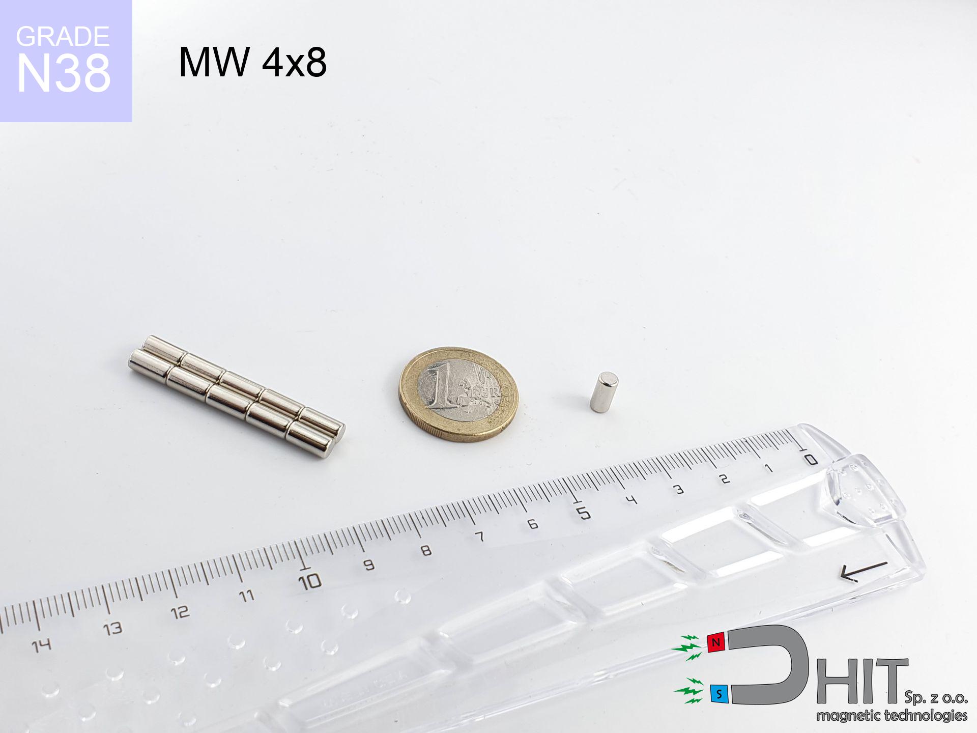
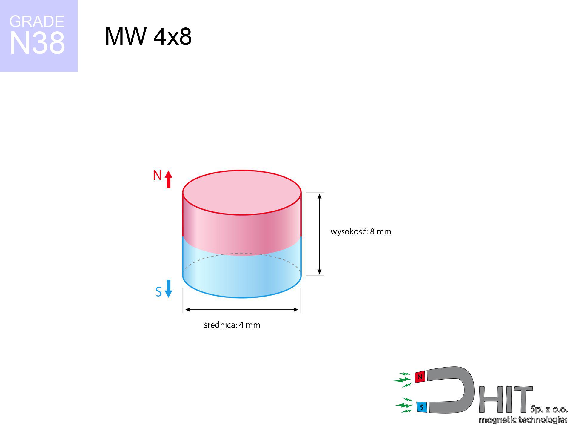
MW 4x8 / N38 - cylindrical magnet
cylindrical magnet
Catalog no 010079
GTIN/EAN: 5906301810780
- Diameter Ø
- 4 mm [±0,1 mm]
- Height
- 8 mm [±0,1 mm]
- Weight
- 0.75 g
- Magnetization Direction
- ↑ axial
- Coating
- [NiCuNi] Nickel
How we measure these parameters — certificates and measurements
0.570 zł net / pcs
0.701 zł with VAT (23% VAT) / pcs
bulk discounts:
Need more?Frequently asked questions
Where can I buy strong cylindrical neodymium magnets?
Can a small cylindrical magnet provide a strong grip for precise workshop work?
Which cylindrical magnet can work at a higher temperature?
Engineering report for this magnet
Full PDF analysis: pull and shear force, effect of distance, temperature and plate thickness, safety distances and the demagnetization curve.
Call us now
+48 888 99 98 98
alternatively let us know using
contact form
the contact section.
Specifications and structure of a neodymium magnet can be estimated using our
power calculator.
Order by 14:00 and we’ll ship today!
Detailed specification - MW 4x8 / N38 - cylindrical magnet
Specification / characteristics - MW 4x8 / N38 - cylindrical magnet
| properties | values |
|---|---|
| Cat. no. | 010079 |
| GTIN/EAN | 5906301810780 |
| Production/Distribution | Dhit sp. z o.o. |
| Country of origin | Poland / China / Germany |
| Customs code | 85059029 |
| Diameter Ø | 4 mm [±0,1 mm] |
| Height | 8 mm [±0,1 mm] |
| Weight | 0.75 g |
| Magnetization Direction | ↑ axial |
| Load capacity ~ ? | 0.35 kg / 3.48 N |
| Magnetic Induction ~ ? | 599.59 mT / 5996 Gs |
| Coating | [NiCuNi] Nickel |
| Manufacturing Tolerance | ±0.1 mm |
Magnetic properties of material N38
| properties | values | units |
|---|---|---|
| Remanence Br ? | 12.2-12.6 | kGs |
| Remanence Br ? | 1220-1260 | mT |
| Coercivity bHc ? | 10.8-11.5 | kOe |
| Coercivity bHc ? | 860-915 | kA/m |
| Intrinsic coercivity iHc | ≥ 12 | kOe |
| Intrinsic coercivity iHc | ≥ 955 | kA/m |
| Energy product BHmax ? | 36-38 | BH max MGOe |
| Energy product BHmax ? | 287-303 | BH max KJ/m |
| Maximum working temperature ? | ≤ 80 | °C |
Physical properties of sintered neodymium magnets Nd2Fe14B at 20°C
| properties | values | units |
|---|---|---|
| Vickers hardness | ≥550 | Hv |
| Density | ≥7.4 | g/cm3 |
| Curie Temperature TC | 310 | °C |
| Curie Temperature TF | 590 | °F |
| Specific resistance | 150 | μΩ⋅cm |
| Bending strength | 250 | MPa |
| Compressive strength | 1000~1100 | MPa |
| Thermal expansion parallel (∥) to orientation (M) | (3-4) x 10-6 | °C-1 |
| Thermal expansion perpendicular (⊥) to orientation (M) | -(1-3) x 10-6 | °C-1 |
| Young's modulus | 1.7 x 10⁴ | kg/mm² |
Technical simulation of the product - technical parameters
These data are the direct effect of a engineering analysis. Results rely on models for the material Nd2Fe14B. Real-world conditions might slightly differ from theoretical values. Use these data as a reference point for designers.
Table 1: Static pull force (force vs distance) - power drop
MW 4x8 / N38
| Distance (mm) | Induction (Gauss) / mT | Pull Force (kg/lbs/g/N) | Risk Status |
|---|---|---|---|
| 0 mm |
5984 Gs
598.4 mT
|
0.35 kg / 0.77 LBS
350.0 g / 3.4 N
|
low risk |
| 1 mm |
3280 Gs
328.0 mT
|
0.11 kg / 0.23 LBS
105.1 g / 1.0 N
|
low risk |
| 2 mm |
1696 Gs
169.6 mT
|
0.03 kg / 0.06 LBS
28.1 g / 0.3 N
|
low risk |
| 3 mm |
941 Gs
94.1 mT
|
0.01 kg / 0.02 LBS
8.7 g / 0.1 N
|
low risk |
| 5 mm |
371 Gs
37.1 mT
|
0.00 kg / 0.00 LBS
1.3 g / 0.0 N
|
low risk |
| 10 mm |
82 Gs
8.2 mT
|
0.00 kg / 0.00 LBS
0.1 g / 0.0 N
|
low risk |
| 15 mm |
31 Gs
3.1 mT
|
0.00 kg / 0.00 LBS
0.0 g / 0.0 N
|
low risk |
| 20 mm |
15 Gs
1.5 mT
|
0.00 kg / 0.00 LBS
0.0 g / 0.0 N
|
low risk |
| 30 mm |
5 Gs
0.5 mT
|
0.00 kg / 0.00 LBS
0.0 g / 0.0 N
|
low risk |
| 50 mm |
1 Gs
0.1 mT
|
0.00 kg / 0.00 LBS
0.0 g / 0.0 N
|
low risk |
Table 2: Slippage load (vertical surface)
MW 4x8 / N38
| Distance (mm) | Friction coefficient | Pull Force (kg/lbs/g/N) |
|---|---|---|
| 0 mm | Stal (~0.2) |
0.07 kg / 0.15 LBS
70.0 g / 0.7 N
|
| 1 mm | Stal (~0.2) |
0.02 kg / 0.05 LBS
22.0 g / 0.2 N
|
| 2 mm | Stal (~0.2) |
0.01 kg / 0.01 LBS
6.0 g / 0.1 N
|
| 3 mm | Stal (~0.2) |
0.00 kg / 0.00 LBS
2.0 g / 0.0 N
|
| 5 mm | Stal (~0.2) |
0.00 kg / 0.00 LBS
0.0 g / 0.0 N
|
| 10 mm | Stal (~0.2) |
0.00 kg / 0.00 LBS
0.0 g / 0.0 N
|
| 15 mm | Stal (~0.2) |
0.00 kg / 0.00 LBS
0.0 g / 0.0 N
|
| 20 mm | Stal (~0.2) |
0.00 kg / 0.00 LBS
0.0 g / 0.0 N
|
| 30 mm | Stal (~0.2) |
0.00 kg / 0.00 LBS
0.0 g / 0.0 N
|
| 50 mm | Stal (~0.2) |
0.00 kg / 0.00 LBS
0.0 g / 0.0 N
|
Table 3: Wall mounting (sliding) - behavior on slippery surfaces
MW 4x8 / N38
| Surface type | Friction coefficient / % Mocy | Max load (kg/lbs/g/N) |
|---|---|---|
| Raw steel |
µ = 0.3
30% Nominalnej Siły
|
0.11 kg / 0.23 LBS
105.0 g / 1.0 N
|
| Painted steel (standard) |
µ = 0.2
20% Nominalnej Siły
|
0.07 kg / 0.15 LBS
70.0 g / 0.7 N
|
| Oily/slippery steel |
µ = 0.1
10% Nominalnej Siły
|
0.03 kg / 0.08 LBS
35.0 g / 0.3 N
|
| Magnet with anti-slip rubber |
µ = 0.5
50% Nominalnej Siły
|
0.18 kg / 0.39 LBS
175.0 g / 1.7 N
|
Table 4: Material efficiency (saturation) - power losses
MW 4x8 / N38
| Steel thickness (mm) | % power | Real pull force (kg/lbs/g/N) |
|---|---|---|
| 0.5 mm |
|
0.03 kg / 0.08 LBS
35.0 g / 0.3 N
|
| 1 mm |
|
0.09 kg / 0.19 LBS
87.5 g / 0.9 N
|
| 2 mm |
|
0.18 kg / 0.39 LBS
175.0 g / 1.7 N
|
| 3 mm |
|
0.26 kg / 0.58 LBS
262.5 g / 2.6 N
|
| 5 mm |
|
0.35 kg / 0.77 LBS
350.0 g / 3.4 N
|
| 10 mm |
|
0.35 kg / 0.77 LBS
350.0 g / 3.4 N
|
| 11 mm |
|
0.35 kg / 0.77 LBS
350.0 g / 3.4 N
|
| 12 mm |
|
0.35 kg / 0.77 LBS
350.0 g / 3.4 N
|
Table 5: Thermal stability (stability) - power drop
MW 4x8 / N38
| Ambient temp. (°C) | Power loss | Remaining pull (kg/lbs/g/N) | Status |
|---|---|---|---|
| 20 °C | 0.0% |
0.35 kg / 0.77 LBS
350.0 g / 3.4 N
|
OK |
| 40 °C | -2.2% |
0.34 kg / 0.75 LBS
342.3 g / 3.4 N
|
OK |
| 60 °C | -4.4% |
0.33 kg / 0.74 LBS
334.6 g / 3.3 N
|
OK |
| 80 °C | -6.6% |
0.33 kg / 0.72 LBS
326.9 g / 3.2 N
|
|
| 100 °C | -28.8% |
0.25 kg / 0.55 LBS
249.2 g / 2.4 N
|
Table 6: Magnet-Magnet interaction (repulsion) - forces in the system
MW 4x8 / N38
| Gap (mm) | Attraction (kg/lbs) (N-S) | Shear Strength (kg/lbs/g/N) | Repulsion (kg/lbs) (N-N) |
|---|---|---|---|
| 0 mm |
2.77 kg / 6.12 LBS
6 121 Gs
|
0.42 kg / 0.92 LBS
416 g / 4.1 N
|
N/A |
| 1 mm |
1.59 kg / 3.51 LBS
9 063 Gs
|
0.24 kg / 0.53 LBS
239 g / 2.3 N
|
1.43 kg / 3.16 LBS
~0 Gs
|
| 2 mm |
0.83 kg / 1.84 LBS
6 559 Gs
|
0.12 kg / 0.28 LBS
125 g / 1.2 N
|
0.75 kg / 1.65 LBS
~0 Gs
|
| 3 mm |
0.43 kg / 0.94 LBS
4 694 Gs
|
0.06 kg / 0.14 LBS
64 g / 0.6 N
|
0.38 kg / 0.85 LBS
~0 Gs
|
| 5 mm |
0.12 kg / 0.27 LBS
2 498 Gs
|
0.02 kg / 0.04 LBS
18 g / 0.2 N
|
0.11 kg / 0.24 LBS
~0 Gs
|
| 10 mm |
0.01 kg / 0.02 LBS
743 Gs
|
0.00 kg / 0.00 LBS
2 g / 0.0 N
|
0.01 kg / 0.02 LBS
~0 Gs
|
| 20 mm |
0.00 kg / 0.00 LBS
165 Gs
|
0.00 kg / 0.00 LBS
0 g / 0.0 N
|
0.00 kg / 0.00 LBS
~0 Gs
|
| 50 mm |
0.00 kg / 0.00 LBS
17 Gs
|
0.00 kg / 0.00 LBS
0 g / 0.0 N
|
0.00 kg / 0.00 LBS
~0 Gs
|
| 60 mm |
0.00 kg / 0.00 LBS
10 Gs
|
0.00 kg / 0.00 LBS
0 g / 0.0 N
|
0.00 kg / 0.00 LBS
~0 Gs
|
| 70 mm |
0.00 kg / 0.00 LBS
7 Gs
|
0.00 kg / 0.00 LBS
0 g / 0.0 N
|
0.00 kg / 0.00 LBS
~0 Gs
|
| 80 mm |
0.00 kg / 0.00 LBS
5 Gs
|
0.00 kg / 0.00 LBS
0 g / 0.0 N
|
0.00 kg / 0.00 LBS
~0 Gs
|
| 90 mm |
0.00 kg / 0.00 LBS
3 Gs
|
0.00 kg / 0.00 LBS
0 g / 0.0 N
|
0.00 kg / 0.00 LBS
~0 Gs
|
| 100 mm |
0.00 kg / 0.00 LBS
3 Gs
|
0.00 kg / 0.00 LBS
0 g / 0.0 N
|
0.00 kg / 0.00 LBS
~0 Gs
|
Table 7: Protective zones (electronics) - precautionary measures
MW 4x8 / N38
| Object / Device | Limit (Gauss) / mT | Safe distance |
|---|---|---|
| Pacemaker | 5 Gs (0.5 mT) | 3.5 cm |
| Hearing aid | 10 Gs (1.0 mT) | 2.5 cm |
| Timepiece | 20 Gs (2.0 mT) | 2.0 cm |
| Phone / Smartphone | 40 Gs (4.0 mT) | 1.5 cm |
| Car key | 50 Gs (5.0 mT) | 1.5 cm |
| Payment card | 400 Gs (40.0 mT) | 0.5 cm |
| HDD hard drive | 600 Gs (60.0 mT) | 0.5 cm |
Table 8: Dynamics (cracking risk) - collision effects
MW 4x8 / N38
| Start from (mm) | Speed (km/h) | Energy (J) | Predicted outcome |
|---|---|---|---|
| 10 mm |
9.99 km/h
(2.77 m/s)
|
0.00 J | |
| 30 mm |
9.99 km/h
(2.77 m/s)
|
0.00 J | |
| 50 mm |
9.99 km/h
(2.77 m/s)
|
0.00 J | |
| 100 mm |
9.99 km/h
(2.78 m/s)
|
0.00 J |
Table 9: Coating parameters (durability)
MW 4x8 / N38
| Technical parameter | Value / Description |
|---|---|
| Coating type | [NiCuNi] Nickel |
| Layer structure | Nickel - Copper - Nickel |
| Layer thickness | 10-20 µm |
| Salt spray test (SST) ? | 24 h |
| Recommended environment | Indoors only (dry) |
Table 10: Construction data (Pc)
MW 4x8 / N38
| Parameter | Value | SI Unit / Description |
|---|---|---|
| Magnetic Flux | 836 Mx | 8.4 µWb |
| Pc Coefficient | 1.21 | High (Stable) |
Table 11: Underwater work (magnet fishing)
MW 4x8 / N38
| Environment | Effective steel pull | Effect |
|---|---|---|
| Air (land) | 0.35 kg | Standard |
| Water (riverbed) |
0.40 kg
(+0.05 kg buoyancy gain)
|
+14.5% |
1. Wall mount (shear)
*Note: On a vertical surface, the magnet holds just a fraction of its nominal pull.
2. Steel saturation
*Thin steel (e.g. 0.5mm PC case) severely limits the holding force.
3. Temperature resistance
N38: the maximum material working temperature is 80°C. Permitted conditions also depend on the shape and magnetic circuit.
4. Demagnetization curve and operating point (B-H)
chart generated for the permeance coefficient Pc (Permeance Coefficient) = 1.21
This simulation demonstrates the magnetic stability of the selected magnet under specific geometric conditions. The solid red line represents the demagnetization curve (material potential), while the dashed blue line is the load line based on the magnet's geometry. The Pc (Permeance Coefficient), also known as the load line slope, is a dimensionless value that describes the relationship between the magnet's shape and its magnetic stability. The intersection of these two lines (the black dot) is the operating point — it determines the actual magnetic flux density generated by the magnet in this specific configuration. A higher Pc value means the magnet is more 'slender' (tall relative to its area), resulting in a higher operating point and better resistance to irreversible demagnetization caused by external fields or temperature. A value of 0.42 is relatively low (typical for flat magnets), meaning the operating point is closer to the 'knee' of the curve — caution is advised when operating at temperatures near the maximum limit to avoid strength loss.
Elemental analysis
| iron (Fe) | 64% – 68% |
| neodymium (Nd) | 29% – 32% |
| boron (B) | 1.1% – 1.2% |
| dysprosium (Dy) | 0.5% – 2.0% |
| coating (Ni-Cu-Ni) | < 0.05% |
Ecology and recycling (GPSR)
| recyclability (EoL) | 100% |
| recycled raw materials | ~10% (pre-cons) |
| carbon footprint | low / zredukowany |
| waste code (EWC) | 16 02 16 |
See also products
![SM 28x375 [2xM8] / N52 - magnetic separator](https://cdn3.dhit.pl/graphics/products/sm-28x375-2xm8-zoj.jpg "SM 28x375 [2xM8] / N52 - magnetic separator")
![UMP 135x40 [M10+M12] GW F600 Lina / N38 - search holder](https://cdn3.dhit.pl/graphics/products/ump-135x40-m10+m12-gw-f600-+lina-sej.jpg "UMP 135x40 [M10+M12] GW F600 Lina / N38 - search holder")
Pros and cons of neodymium magnets.
Advantages
- Their magnetic field remains stable, and after approximately ten years it drops only by ~1% (according to research),
- They do not lose their magnetic properties even under strong external field,
- By applying a smooth coating of silver, the element acquires an elegant look,
- Magnetic induction on the working part of the magnet turns out to be exceptional,
- Neodymium magnets are characterized by very high magnetic induction on the magnet surface and can work (depending on the form) even at a temperature of 230°C or more...
- Due to the ability of flexible shaping and adaptation to specialized solutions, magnetic components can be produced in a variety of geometric configurations, which amplifies use scope,
- Wide application in modern industrial fields – they are utilized in magnetic memories, electric motors, medical equipment, also multitasking production systems.
- Relatively small size with high pulling force – neodymium magnets offer high power in small dimensions, which allows their use in small systems
Cons
- To avoid cracks upon strong impacts, we suggest using special steel housings. Such a solution secures the magnet and simultaneously improves its durability.
- Do not exceed this material temperature limit: 80°C. Overheating may permanently weaken the magnet.
- When exposed to humidity, magnets usually rust. To use them in conditions outside, it is recommended to use protective magnets, such as those in rubber or plastics, which prevent oxidation and corrosion.
- Limited possibility of making nuts in the magnet and complex forms - recommended is a housing - magnet mounting.
- Health risk to health – tiny shards of magnets pose a threat, when accidentally swallowed, which is particularly important in the context of child safety. Additionally, small components of these magnets can be problematic in diagnostics medical after entering the body.
- High unit price – neodymium magnets have a higher price than other types of magnets (e.g. ferrite), which hinders application in large quantities
Holding force characteristics
Highest magnetic holding force – what it depends on?
- with the contact of a sheet made of low-carbon steel, guaranteeing maximum field concentration
- possessing a massiveness of min. 10 mm to avoid saturation
- characterized by smoothness
- with zero gap (no paint)
- for force applied at a right angle (in the magnet axis)
- at room temperature
Lifting capacity in real conditions – factors
- Gap between magnet and steel – every millimeter of distance (caused e.g. by veneer or unevenness) significantly weakens the magnet efficiency, often by half at just 0.5 mm.
- Force direction – declared lifting capacity refers to detachment vertically. When slipping, the magnet exhibits much less (typically approx. 20-30% of maximum force).
- Wall thickness – thin material does not allow full use of the magnet. Part of the magnetic field passes through the material instead of converting into lifting capacity.
- Steel grade – the best choice is pure iron steel. Hardened steels may have worse magnetic properties.
- Surface structure – the more even the surface, the better the adhesion and higher the lifting capacity. Unevenness acts like micro-gaps.
- Temperature – heating the magnet causes a temporary drop of force. It is worth remembering the maximum operating temperature for a given model.
Lifting capacity testing was carried out on plates with a smooth surface of suitable thickness, under a perpendicular pulling force, whereas under shearing force the load capacity is reduced by as much as 5 times. Additionally, even a minimal clearance between the magnet’s surface and the plate lowers the load capacity.
Precautions when working with neodymium magnets
Physical harm
Big blocks can crush fingers in a fraction of a second. Do not put your hand between two strong magnets.
Machining danger
Drilling and cutting of neodymium magnets carries a risk of fire hazard. Magnetic powder oxidizes rapidly with oxygen and is difficult to extinguish.
Eye protection
NdFeB magnets are ceramic materials, which means they are fragile like glass. Collision of two magnets will cause them cracking into shards.
GPS Danger
Be aware: rare earth magnets generate a field that interferes with sensitive sensors. Keep a separation from your mobile, device, and GPS.
Sensitization to coating
Allergy Notice: The nickel-copper-nickel coating contains nickel. If skin irritation appears, cease working with magnets and wear gloves.
Heat sensitivity
Keep cool. Neodymium magnets are susceptible to temperature. If you require operation above 80°C, look for special high-temperature series (H, SH, UH).
Do not underestimate power
Handle with care. Neodymium magnets act from a long distance and connect with massive power, often quicker than you can move away.
This is not a toy
Strictly keep magnets out of reach of children. Choking hazard is significant, and the consequences of magnets connecting inside the body are fatal.
Safe distance
Very strong magnetic fields can erase data on payment cards, HDDs, and storage devices. Stay away of min. 10 cm.
Medical interference
Individuals with a pacemaker should maintain an absolute distance from magnets. The magnetic field can disrupt the operation of the life-saving device.
Tabela kosztu i czasu dostawy
Płatność przed wysyłką:

GLS kurier
Przesyłka będzie u Ciebie za 2-3 dni
14.99 ZŁ

InPost Paczkomaty 24/7
Przesyłka będzie u Ciebie za 1-2 dni
12.30 ZŁ
Płatność przy odbiorze (pobranie):
GLS kurier
Przesyłka będzie u Ciebie za 1-2 dni
23.00 ZŁ