

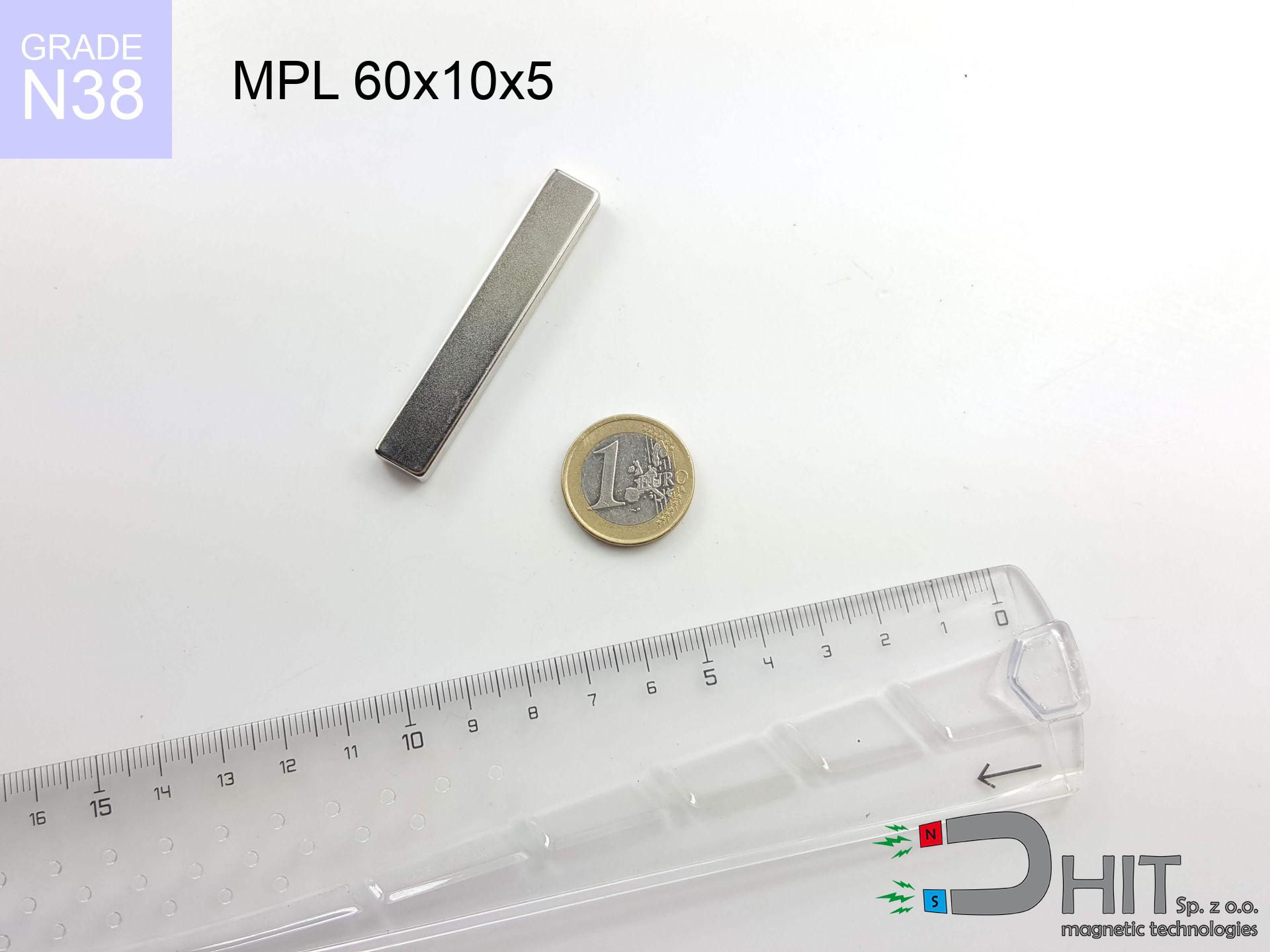
MPL 60x10x5 / N38 - lamellar magnet
lamellar magnet
Catalog no 020474
GTIN/EAN: 5906301811947
- length
- 60 mm [±0,1 mm]
- Width
- 10 mm [±0,1 mm]
- Height
- 5 mm [±0,1 mm]
- Weight
- 22.5 g
- Magnetization Direction
- ↑ axial
- Coating
- [NiCuNi] Nickel
How we measure these parameters — certificates and measurements
15.45 zł net / pcs
19.00 zł with VAT (23% VAT) / pcs
bulk discounts:
Need more?Frequently asked questions
What pull rating should I choose for a workshop block magnet?
Are block neodymium magnets available in more durable versions?
How should I choose block magnets for mounting a structure?
Engineering report for this magnet
Full PDF analysis: pull and shear force, effect of distance, temperature and plate thickness, safety distances and the demagnetization curve.
Call us now
+48 888 99 98 98
alternatively let us know using
contact form
the contact section.
Specifications and structure of a neodymium magnet can be estimated using our
power calculator.
Order by 14:00 and we’ll ship today!
Product card - MPL 60x10x5 / N38 - lamellar magnet
Specification / characteristics - MPL 60x10x5 / N38 - lamellar magnet
| properties | values |
|---|---|
| Cat. no. | 020474 |
| GTIN/EAN | 5906301811947 |
| Production/Distribution | Dhit sp. z o.o. |
| Country of origin | Poland / China / Germany |
| Customs code | 85059029 |
| length | 60 mm [±0,1 mm] |
| Width | 10 mm [±0,1 mm] |
| Height | 5 mm [±0,1 mm] |
| Weight | 22.5 g |
| Magnetization Direction | ↑ axial |
| Load capacity ~ ? | 18.16 kg / 178.10 N |
| Magnetic Induction ~ ? | 315.09 mT / 3151 Gs |
| Coating | [NiCuNi] Nickel |
| Manufacturing Tolerance | ±0.1 mm |
Magnetic properties of material N38
| properties | values | units |
|---|---|---|
| Remanence Br ? | 12.2-12.6 | kGs |
| Remanence Br ? | 1220-1260 | mT |
| Coercivity bHc ? | 10.8-11.5 | kOe |
| Coercivity bHc ? | 860-915 | kA/m |
| Intrinsic coercivity iHc | ≥ 12 | kOe |
| Intrinsic coercivity iHc | ≥ 955 | kA/m |
| Energy product BHmax ? | 36-38 | BH max MGOe |
| Energy product BHmax ? | 287-303 | BH max KJ/m |
| Maximum working temperature ? | ≤ 80 | °C |
Physical properties of sintered neodymium magnets Nd2Fe14B at 20°C
| properties | values | units |
|---|---|---|
| Vickers hardness | ≥550 | Hv |
| Density | ≥7.4 | g/cm3 |
| Curie Temperature TC | 310 | °C |
| Curie Temperature TF | 590 | °F |
| Specific resistance | 150 | μΩ⋅cm |
| Bending strength | 250 | MPa |
| Compressive strength | 1000~1100 | MPa |
| Thermal expansion parallel (∥) to orientation (M) | (3-4) x 10-6 | °C-1 |
| Thermal expansion perpendicular (⊥) to orientation (M) | -(1-3) x 10-6 | °C-1 |
| Young's modulus | 1.7 x 10⁴ | kg/mm² |
Physical simulation of the assembly - report
The following information are the direct effect of a mathematical simulation. Values were calculated on algorithms for the class Nd2Fe14B. Actual parameters might slightly differ from theoretical values. Use these calculations as a preliminary roadmap during assembly planning.
Table 1: Static pull force (force vs distance) - characteristics
MPL 60x10x5 / N38
| Distance (mm) | Induction (Gauss) / mT | Pull Force (kg/lbs/g/N) | Risk Status |
|---|---|---|---|
| 0 mm |
3149 Gs
314.9 mT
|
18.16 kg / 40.04 pounds
18160.0 g / 178.1 N
|
critical level |
| 1 mm |
2731 Gs
273.1 mT
|
13.66 kg / 30.11 pounds
13658.3 g / 134.0 N
|
critical level |
| 2 mm |
2302 Gs
230.2 mT
|
9.70 kg / 21.38 pounds
9698.4 g / 95.1 N
|
warning |
| 3 mm |
1912 Gs
191.2 mT
|
6.70 kg / 14.76 pounds
6696.5 g / 65.7 N
|
warning |
| 5 mm |
1317 Gs
131.7 mT
|
3.18 kg / 7.00 pounds
3176.9 g / 31.2 N
|
warning |
| 10 mm |
598 Gs
59.8 mT
|
0.65 kg / 1.44 pounds
653.8 g / 6.4 N
|
safe |
| 15 mm |
330 Gs
33.0 mT
|
0.20 kg / 0.44 pounds
199.2 g / 2.0 N
|
safe |
| 20 mm |
205 Gs
20.5 mT
|
0.08 kg / 0.17 pounds
77.0 g / 0.8 N
|
safe |
| 30 mm |
96 Gs
9.6 mT
|
0.02 kg / 0.04 pounds
16.9 g / 0.2 N
|
safe |
| 50 mm |
31 Gs
3.1 mT
|
0.00 kg / 0.00 pounds
1.8 g / 0.0 N
|
safe |
Table 2: Shear capacity (wall)
MPL 60x10x5 / N38
| Distance (mm) | Friction coefficient | Pull Force (kg/lbs/g/N) |
|---|---|---|
| 0 mm | Stal (~0.2) |
3.63 kg / 8.01 pounds
3632.0 g / 35.6 N
|
| 1 mm | Stal (~0.2) |
2.73 kg / 6.02 pounds
2732.0 g / 26.8 N
|
| 2 mm | Stal (~0.2) |
1.94 kg / 4.28 pounds
1940.0 g / 19.0 N
|
| 3 mm | Stal (~0.2) |
1.34 kg / 2.95 pounds
1340.0 g / 13.1 N
|
| 5 mm | Stal (~0.2) |
0.64 kg / 1.40 pounds
636.0 g / 6.2 N
|
| 10 mm | Stal (~0.2) |
0.13 kg / 0.29 pounds
130.0 g / 1.3 N
|
| 15 mm | Stal (~0.2) |
0.04 kg / 0.09 pounds
40.0 g / 0.4 N
|
| 20 mm | Stal (~0.2) |
0.02 kg / 0.04 pounds
16.0 g / 0.2 N
|
| 30 mm | Stal (~0.2) |
0.00 kg / 0.01 pounds
4.0 g / 0.0 N
|
| 50 mm | Stal (~0.2) |
0.00 kg / 0.00 pounds
0.0 g / 0.0 N
|
Table 3: Wall mounting (sliding) - vertical pull
MPL 60x10x5 / N38
| Surface type | Friction coefficient / % Mocy | Max load (kg/lbs/g/N) |
|---|---|---|
| Raw steel |
µ = 0.3
30% Nominalnej Siły
|
5.45 kg / 12.01 pounds
5448.0 g / 53.4 N
|
| Painted steel (standard) |
µ = 0.2
20% Nominalnej Siły
|
3.63 kg / 8.01 pounds
3632.0 g / 35.6 N
|
| Oily/slippery steel |
µ = 0.1
10% Nominalnej Siły
|
1.82 kg / 4.00 pounds
1816.0 g / 17.8 N
|
| Magnet with anti-slip rubber |
µ = 0.5
50% Nominalnej Siły
|
9.08 kg / 20.02 pounds
9080.0 g / 89.1 N
|
Table 4: Material efficiency (substrate influence) - power losses
MPL 60x10x5 / N38
| Steel thickness (mm) | % power | Real pull force (kg/lbs/g/N) |
|---|---|---|
| 0.5 mm |
|
0.91 kg / 2.00 pounds
908.0 g / 8.9 N
|
| 1 mm |
|
2.27 kg / 5.00 pounds
2270.0 g / 22.3 N
|
| 2 mm |
|
4.54 kg / 10.01 pounds
4540.0 g / 44.5 N
|
| 3 mm |
|
6.81 kg / 15.01 pounds
6810.0 g / 66.8 N
|
| 5 mm |
|
11.35 kg / 25.02 pounds
11350.0 g / 111.3 N
|
| 10 mm |
|
18.16 kg / 40.04 pounds
18160.0 g / 178.1 N
|
| 11 mm |
|
18.16 kg / 40.04 pounds
18160.0 g / 178.1 N
|
| 12 mm |
|
18.16 kg / 40.04 pounds
18160.0 g / 178.1 N
|
Table 5: Thermal resistance (material behavior) - power drop
MPL 60x10x5 / N38
| Ambient temp. (°C) | Power loss | Remaining pull (kg/lbs/g/N) | Status |
|---|---|---|---|
| 20 °C | 0.0% |
18.16 kg / 40.04 pounds
18160.0 g / 178.1 N
|
OK |
| 40 °C | -2.2% |
17.76 kg / 39.16 pounds
17760.5 g / 174.2 N
|
OK |
| 60 °C | -4.4% |
17.36 kg / 38.27 pounds
17361.0 g / 170.3 N
|
|
| 80 °C | -6.6% |
16.96 kg / 37.39 pounds
16961.4 g / 166.4 N
|
|
| 100 °C | -28.8% |
12.93 kg / 28.51 pounds
12929.9 g / 126.8 N
|
Table 6: Magnet-Magnet interaction (attraction) - field range
MPL 60x10x5 / N38
| Gap (mm) | Attraction (kg/lbs) (N-S) | Shear Strength (kg/lbs/g/N) | Repulsion (kg/lbs) (N-N) |
|---|---|---|---|
| 0 mm |
36.69 kg / 80.89 pounds
4 464 Gs
|
5.50 kg / 12.13 pounds
5503 g / 54.0 N
|
N/A |
| 1 mm |
32.13 kg / 70.84 pounds
5 895 Gs
|
4.82 kg / 10.63 pounds
4820 g / 47.3 N
|
28.92 kg / 63.76 pounds
~0 Gs
|
| 2 mm |
27.59 kg / 60.83 pounds
5 463 Gs
|
4.14 kg / 9.13 pounds
4139 g / 40.6 N
|
24.83 kg / 54.75 pounds
~0 Gs
|
| 3 mm |
23.37 kg / 51.53 pounds
5 027 Gs
|
3.51 kg / 7.73 pounds
3506 g / 34.4 N
|
21.03 kg / 46.37 pounds
~0 Gs
|
| 5 mm |
16.31 kg / 35.97 pounds
4 200 Gs
|
2.45 kg / 5.39 pounds
2447 g / 24.0 N
|
14.68 kg / 32.37 pounds
~0 Gs
|
| 10 mm |
6.42 kg / 14.15 pounds
2 635 Gs
|
0.96 kg / 2.12 pounds
963 g / 9.4 N
|
5.78 kg / 12.74 pounds
~0 Gs
|
| 20 mm |
1.32 kg / 2.91 pounds
1 195 Gs
|
0.20 kg / 0.44 pounds
198 g / 1.9 N
|
1.19 kg / 2.62 pounds
~0 Gs
|
| 50 mm |
0.07 kg / 0.15 pounds
274 Gs
|
0.01 kg / 0.02 pounds
10 g / 0.1 N
|
0.06 kg / 0.14 pounds
~0 Gs
|
| 60 mm |
0.03 kg / 0.08 pounds
192 Gs
|
0.01 kg / 0.01 pounds
5 g / 0.1 N
|
0.03 kg / 0.07 pounds
~0 Gs
|
| 70 mm |
0.02 kg / 0.04 pounds
140 Gs
|
0.00 kg / 0.01 pounds
3 g / 0.0 N
|
0.02 kg / 0.04 pounds
~0 Gs
|
| 80 mm |
0.01 kg / 0.02 pounds
104 Gs
|
0.00 kg / 0.00 pounds
2 g / 0.0 N
|
0.01 kg / 0.02 pounds
~0 Gs
|
| 90 mm |
0.01 kg / 0.01 pounds
80 Gs
|
0.00 kg / 0.00 pounds
1 g / 0.0 N
|
0.00 kg / 0.00 pounds
~0 Gs
|
| 100 mm |
0.00 kg / 0.01 pounds
62 Gs
|
0.00 kg / 0.00 pounds
1 g / 0.0 N
|
0.00 kg / 0.00 pounds
~0 Gs
|
Table 7: Hazards (electronics) - precautionary measures
MPL 60x10x5 / N38
| Object / Device | Limit (Gauss) / mT | Safe distance |
|---|---|---|
| Pacemaker | 5 Gs (0.5 mT) | 10.5 cm |
| Hearing aid | 10 Gs (1.0 mT) | 8.0 cm |
| Timepiece | 20 Gs (2.0 mT) | 6.0 cm |
| Phone / Smartphone | 40 Gs (4.0 mT) | 4.5 cm |
| Car key | 50 Gs (5.0 mT) | 4.5 cm |
| Payment card | 400 Gs (40.0 mT) | 1.5 cm |
| HDD hard drive | 600 Gs (60.0 mT) | 1.0 cm |
Table 8: Impact energy (cracking risk) - warning
MPL 60x10x5 / N38
| Start from (mm) | Speed (km/h) | Energy (J) | Predicted outcome |
|---|---|---|---|
| 10 mm |
24.43 km/h
(6.79 m/s)
|
0.52 J | |
| 30 mm |
25.09 km/h
(6.97 m/s)
|
0.55 J | |
| 50 mm |
25.11 km/h
(6.97 m/s)
|
0.55 J | |
| 100 mm |
25.12 km/h
(6.98 m/s)
|
0.55 J |
Table 9: Anti-corrosion coating durability
MPL 60x10x5 / N38
| Technical parameter | Value / Description |
|---|---|
| Coating type | [NiCuNi] Nickel |
| Layer structure | Nickel - Copper - Nickel |
| Layer thickness | 10-20 µm |
| Salt spray test (SST) ? | 24 h |
| Recommended environment | Indoors only (dry) |
Table 10: Electrical data (Pc)
MPL 60x10x5 / N38
| Parameter | Value | SI Unit / Description |
|---|---|---|
| Magnetic Flux | 14 969 Mx | 149.7 µWb |
| Pc Coefficient | 0.26 | Low (Flat) |
Table 11: Physics of underwater searching
MPL 60x10x5 / N38
| Environment | Effective steel pull | Effect |
|---|---|---|
| Air (land) | 18.16 kg | Standard |
| Water (riverbed) |
20.79 kg
(+2.63 kg buoyancy gain)
|
+14.5% |
1. Wall mount (shear)
*Note: On a vertical wall, the magnet holds just ~20% of its perpendicular strength.
2. Efficiency vs thickness
*Thin steel (e.g. 0.5mm PC case) significantly reduces the holding force.
3. Heat tolerance
N38: the maximum material working temperature is 80°C. Permitted conditions also depend on the shape and magnetic circuit.
4. Demagnetization curve and operating point (B-H)
chart generated for the permeance coefficient Pc (Permeance Coefficient) = 0.26
This simulation demonstrates the magnetic stability of the selected magnet under specific geometric conditions. The solid red line represents the demagnetization curve (material potential), while the dashed blue line is the load line based on the magnet's geometry. The Pc (Permeance Coefficient), also known as the load line slope, is a dimensionless value that describes the relationship between the magnet's shape and its magnetic stability. The intersection of these two lines (the black dot) is the operating point — it determines the actual magnetic flux density generated by the magnet in this specific configuration. A higher Pc value means the magnet is more 'slender' (tall relative to its area), resulting in a higher operating point and better resistance to irreversible demagnetization caused by external fields or temperature. A value of 0.42 is relatively low (typical for flat magnets), meaning the operating point is closer to the 'knee' of the curve — caution is advised when operating at temperatures near the maximum limit to avoid strength loss.
Material specification
| iron (Fe) | 64% – 68% |
| neodymium (Nd) | 29% – 32% |
| boron (B) | 1.1% – 1.2% |
| dysprosium (Dy) | 0.5% – 2.0% |
| coating (Ni-Cu-Ni) | < 0.05% |
Sustainability
| recyclability (EoL) | 100% |
| recycled raw materials | ~10% (pre-cons) |
| carbon footprint | low / zredukowany |
| waste code (EWC) | 16 02 16 |
See also products
![UMGW 20x15x7 [M4] GW / N38 - magnetic holder internal thread](https://cdn3.dhit.pl/graphics/products/um-20x15x7-m4-gw-big.jpg "UMGW 20x15x7 [M4] GW / N38 - magnetic holder internal thread")

Strengths as well as weaknesses of Nd2Fe14B magnets.
Pros
- They have stable power, and over around ten years their performance decreases symbolically – ~1% (according to theory),
- They are noted for resistance to demagnetization induced by external disturbances,
- By using a reflective coating of silver, the element has an modern look,
- Magnetic induction on the working part of the magnet turns out to be strong,
- Due to their durability and thermal resistance, neodymium magnets can operate (depending on the shape) even at high temperatures reaching 230°C or more...
- Thanks to flexibility in designing and the ability to adapt to client solutions,
- Wide application in modern technologies – they are used in data components, drive modules, precision medical tools, as well as modern systems.
- Thanks to efficiency per cm³, small magnets offer high operating force, with minimal size,
Disadvantages
- To avoid cracks under impact, we recommend using special steel housings. Such a solution secures the magnet and simultaneously increases its durability.
- Do not exceed this material temperature limit: 80°C. Overheating may permanently weaken the magnet.
- When exposed to humidity, magnets usually rust. To use them in conditions outside, it is recommended to use protective magnets, such as magnets in rubber or plastics, which secure oxidation as well as corrosion.
- We suggest casing - magnetic mount, due to difficulties in realizing threads inside the magnet and complicated shapes.
- Health risk resulting from small fragments of magnets pose a threat, if swallowed, which is particularly important in the aspect of protecting the youngest. Furthermore, small components of these products can complicate diagnosis medical after entering the body.
- Higher cost of purchase is one of the disadvantages compared to ceramic magnets, especially in budget applications
Holding force characteristics
Maximum lifting capacity of the magnet – what it depends on?
- on a base made of structural steel, effectively closing the magnetic flux
- possessing a thickness of at least 10 mm to avoid saturation
- with a plane cleaned and smooth
- with zero gap (no coatings)
- during detachment in a direction perpendicular to the mounting surface
- in temp. approx. 20°C
Lifting capacity in practice – influencing factors
- Clearance – the presence of foreign body (paint, tape, gap) interrupts the magnetic circuit, which lowers power rapidly (even by 50% at 0.5 mm).
- Loading method – catalog parameter refers to pulling vertically. When applying parallel force, the magnet exhibits significantly lower power (typically approx. 20-30% of maximum force).
- Metal thickness – the thinner the sheet, the weaker the hold. Part of the magnetic field passes through the material instead of converting into lifting capacity.
- Material type – ideal substrate is pure iron steel. Cast iron may generate lower lifting capacity.
- Plate texture – smooth surfaces guarantee perfect abutment, which improves field saturation. Uneven metal weaken the grip.
- Thermal environment – heating the magnet results in weakening of force. Check the thermal limit for a given model.
Lifting capacity testing was carried out on a smooth plate of suitable thickness, under a perpendicular pulling force, in contrast under parallel forces the lifting capacity is smaller. In addition, even a slight gap between the magnet’s surface and the plate decreases the lifting capacity.
Safety rules for work with NdFeB magnets
Do not drill into magnets
Fire hazard: Rare earth powder is explosive. Do not process magnets in home conditions as this risks ignition.
Compass and GPS
A strong magnetic field interferes with the functioning of compasses in phones and navigation systems. Keep magnets near a smartphone to prevent damaging the sensors.
Health Danger
Patients with a heart stimulator should keep an safe separation from magnets. The magnetism can interfere with the operation of the implant.
Adults only
Always keep magnets out of reach of children. Risk of swallowing is high, and the consequences of magnets connecting inside the body are fatal.
Bodily injuries
Protect your hands. Two large magnets will join immediately with a force of massive weight, destroying everything in their path. Exercise extreme caution!
Powerful field
Use magnets with awareness. Their immense force can shock even experienced users. Be vigilant and do not underestimate their force.
Heat sensitivity
Standard neodymium magnets (N-type) lose magnetization when the temperature surpasses 80°C. This process is irreversible.
Cards and drives
Do not bring magnets near a purse, computer, or screen. The magnetic field can permanently damage these devices and wipe information from cards.
Avoid contact if allergic
Allergy Notice: The Ni-Cu-Ni coating consists of nickel. If redness occurs, cease working with magnets and use protective gear.
Beware of splinters
Despite metallic appearance, neodymium is delicate and not impact-resistant. Avoid impacts, as the magnet may shatter into hazardous fragments.
Tabela kosztu i czasu dostawy
Płatność przed wysyłką:

GLS kurier
Przesyłka będzie u Ciebie za 2-3 dni
14.99 ZŁ

InPost Paczkomaty 24/7
Przesyłka będzie u Ciebie za 1-2 dni
12.30 ZŁ
Płatność przy odbiorze (pobranie):
GLS kurier
Przesyłka będzie u Ciebie za 1-2 dni
23.00 ZŁ