

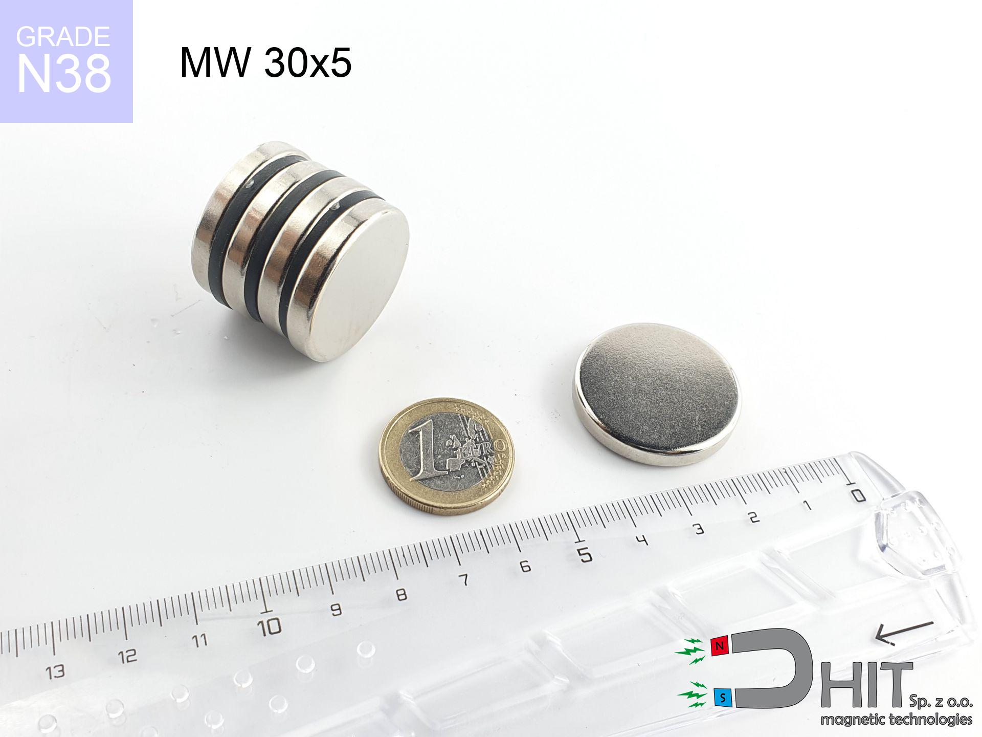
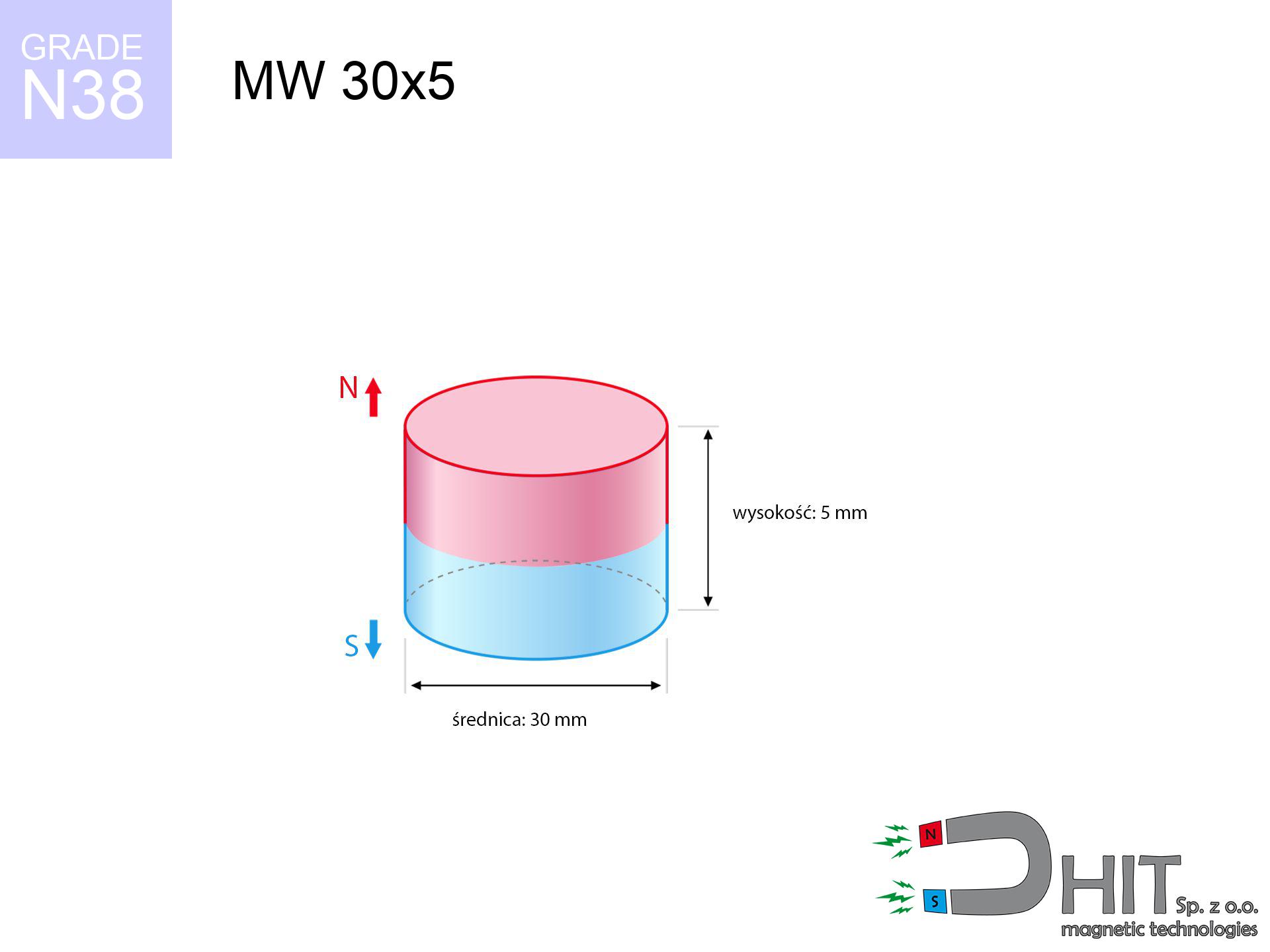
MW 30x5 / N38 - cylindrical magnet
cylindrical magnet
Catalog no 010056
GTIN/EAN: 5906301810551
- Diameter Ø
- 30 mm [±0,1 mm]
- Height
- 5 mm [±0,1 mm]
- Weight
- 26.51 g
- Magnetization Direction
- ↑ axial
- Coating
- [NiCuNi] Nickel
How we measure these parameters — certificates and measurements
6.79 zł net / pcs
8.35 zł with VAT (23% VAT) / pcs
bulk discounts:
Need more?Frequently asked questions
Where can I buy strong cylindrical neodymium magnets?
Can a small cylindrical magnet provide a strong grip for precise workshop work?
Which cylindrical magnet can work at a higher temperature?
Engineering report for this magnet
Full PDF analysis: pull and shear force, effect of distance, temperature and plate thickness, safety distances and the demagnetization curve.
Call us now
+48 888 99 98 98
alternatively let us know using
contact form
the contact section.
Specifications and structure of a neodymium magnet can be estimated using our
power calculator.
Order by 14:00 and we’ll ship today!
Detailed specification - MW 30x5 / N38 - cylindrical magnet
Specification / characteristics - MW 30x5 / N38 - cylindrical magnet
| properties | values |
|---|---|
| Cat. no. | 010056 |
| GTIN/EAN | 5906301810551 |
| Production/Distribution | Dhit sp. z o.o. |
| Country of origin | Poland / China / Germany |
| Customs code | 85059029 |
| Diameter Ø | 30 mm [±0,1 mm] |
| Height | 5 mm [±0,1 mm] |
| Weight | 26.51 g |
| Magnetization Direction | ↑ axial |
| Load capacity ~ ? | 8.71 kg / 85.42 N |
| Magnetic Induction ~ ? | 196.02 mT / 1960 Gs |
| Coating | [NiCuNi] Nickel |
| Manufacturing Tolerance | ±0.1 mm |
Magnetic properties of material N38
| properties | values | units |
|---|---|---|
| Remanence Br ? | 12.2-12.6 | kGs |
| Remanence Br ? | 1220-1260 | mT |
| Coercivity bHc ? | 10.8-11.5 | kOe |
| Coercivity bHc ? | 860-915 | kA/m |
| Intrinsic coercivity iHc | ≥ 12 | kOe |
| Intrinsic coercivity iHc | ≥ 955 | kA/m |
| Energy product BHmax ? | 36-38 | BH max MGOe |
| Energy product BHmax ? | 287-303 | BH max KJ/m |
| Maximum working temperature ? | ≤ 80 | °C |
Physical properties of sintered neodymium magnets Nd2Fe14B at 20°C
| properties | values | units |
|---|---|---|
| Vickers hardness | ≥550 | Hv |
| Density | ≥7.4 | g/cm3 |
| Curie Temperature TC | 310 | °C |
| Curie Temperature TF | 590 | °F |
| Specific resistance | 150 | μΩ⋅cm |
| Bending strength | 250 | MPa |
| Compressive strength | 1000~1100 | MPa |
| Thermal expansion parallel (∥) to orientation (M) | (3-4) x 10-6 | °C-1 |
| Thermal expansion perpendicular (⊥) to orientation (M) | -(1-3) x 10-6 | °C-1 |
| Young's modulus | 1.7 x 10⁴ | kg/mm² |
Engineering simulation of the magnet - report
The following values represent the outcome of a physical analysis. Results are based on models for the material Nd2Fe14B. Actual conditions might slightly deviate from the simulation results. Please consider these data as a supplementary guide for designers.
Table 1: Static pull force (force vs distance) - characteristics
MW 30x5 / N38
| Distance (mm) | Induction (Gauss) / mT | Pull Force (kg/lbs/g/N) | Risk Status |
|---|---|---|---|
| 0 mm |
1960 Gs
196.0 mT
|
8.71 kg / 19.20 pounds
8710.0 g / 85.4 N
|
medium risk |
| 1 mm |
1890 Gs
189.0 mT
|
8.10 kg / 17.86 pounds
8100.7 g / 79.5 N
|
medium risk |
| 2 mm |
1802 Gs
180.2 mT
|
7.37 kg / 16.24 pounds
7366.2 g / 72.3 N
|
medium risk |
| 3 mm |
1702 Gs
170.2 mT
|
6.57 kg / 14.47 pounds
6565.7 g / 64.4 N
|
medium risk |
| 5 mm |
1479 Gs
147.9 mT
|
4.96 kg / 10.93 pounds
4956.4 g / 48.6 N
|
medium risk |
| 10 mm |
945 Gs
94.5 mT
|
2.02 kg / 4.46 pounds
2024.4 g / 19.9 N
|
medium risk |
| 15 mm |
576 Gs
57.6 mT
|
0.75 kg / 1.66 pounds
752.1 g / 7.4 N
|
low risk |
| 20 mm |
356 Gs
35.6 mT
|
0.29 kg / 0.64 pounds
288.1 g / 2.8 N
|
low risk |
| 30 mm |
153 Gs
15.3 mT
|
0.05 kg / 0.12 pounds
53.2 g / 0.5 N
|
low risk |
| 50 mm |
43 Gs
4.3 mT
|
0.00 kg / 0.01 pounds
4.2 g / 0.0 N
|
low risk |
Table 2: Shear hold (vertical surface)
MW 30x5 / N38
| Distance (mm) | Friction coefficient | Pull Force (kg/lbs/g/N) |
|---|---|---|
| 0 mm | Stal (~0.2) |
1.74 kg / 3.84 pounds
1742.0 g / 17.1 N
|
| 1 mm | Stal (~0.2) |
1.62 kg / 3.57 pounds
1620.0 g / 15.9 N
|
| 2 mm | Stal (~0.2) |
1.47 kg / 3.25 pounds
1474.0 g / 14.5 N
|
| 3 mm | Stal (~0.2) |
1.31 kg / 2.90 pounds
1314.0 g / 12.9 N
|
| 5 mm | Stal (~0.2) |
0.99 kg / 2.19 pounds
992.0 g / 9.7 N
|
| 10 mm | Stal (~0.2) |
0.40 kg / 0.89 pounds
404.0 g / 4.0 N
|
| 15 mm | Stal (~0.2) |
0.15 kg / 0.33 pounds
150.0 g / 1.5 N
|
| 20 mm | Stal (~0.2) |
0.06 kg / 0.13 pounds
58.0 g / 0.6 N
|
| 30 mm | Stal (~0.2) |
0.01 kg / 0.02 pounds
10.0 g / 0.1 N
|
| 50 mm | Stal (~0.2) |
0.00 kg / 0.00 pounds
0.0 g / 0.0 N
|
Table 3: Wall mounting (shearing) - behavior on slippery surfaces
MW 30x5 / N38
| Surface type | Friction coefficient / % Mocy | Max load (kg/lbs/g/N) |
|---|---|---|
| Raw steel |
µ = 0.3
30% Nominalnej Siły
|
2.61 kg / 5.76 pounds
2613.0 g / 25.6 N
|
| Painted steel (standard) |
µ = 0.2
20% Nominalnej Siły
|
1.74 kg / 3.84 pounds
1742.0 g / 17.1 N
|
| Oily/slippery steel |
µ = 0.1
10% Nominalnej Siły
|
0.87 kg / 1.92 pounds
871.0 g / 8.5 N
|
| Magnet with anti-slip rubber |
µ = 0.5
50% Nominalnej Siły
|
4.36 kg / 9.60 pounds
4355.0 g / 42.7 N
|
Table 4: Steel thickness (substrate influence) - sheet metal selection
MW 30x5 / N38
| Steel thickness (mm) | % power | Real pull force (kg/lbs/g/N) |
|---|---|---|
| 0.5 mm |
|
0.87 kg / 1.92 pounds
871.0 g / 8.5 N
|
| 1 mm |
|
2.18 kg / 4.80 pounds
2177.5 g / 21.4 N
|
| 2 mm |
|
4.36 kg / 9.60 pounds
4355.0 g / 42.7 N
|
| 3 mm |
|
6.53 kg / 14.40 pounds
6532.5 g / 64.1 N
|
| 5 mm |
|
8.71 kg / 19.20 pounds
8710.0 g / 85.4 N
|
| 10 mm |
|
8.71 kg / 19.20 pounds
8710.0 g / 85.4 N
|
| 11 mm |
|
8.71 kg / 19.20 pounds
8710.0 g / 85.4 N
|
| 12 mm |
|
8.71 kg / 19.20 pounds
8710.0 g / 85.4 N
|
Table 5: Working in heat (material behavior) - thermal limit
MW 30x5 / N38
| Ambient temp. (°C) | Power loss | Remaining pull (kg/lbs/g/N) | Status |
|---|---|---|---|
| 20 °C | 0.0% |
8.71 kg / 19.20 pounds
8710.0 g / 85.4 N
|
OK |
| 40 °C | -2.2% |
8.52 kg / 18.78 pounds
8518.4 g / 83.6 N
|
OK |
| 60 °C | -4.4% |
8.33 kg / 18.36 pounds
8326.8 g / 81.7 N
|
|
| 80 °C | -6.6% |
8.14 kg / 17.93 pounds
8135.1 g / 79.8 N
|
|
| 100 °C | -28.8% |
6.20 kg / 13.67 pounds
6201.5 g / 60.8 N
|
Table 6: Two magnets (repulsion) - field collision
MW 30x5 / N38
| Gap (mm) | Attraction (kg/lbs) (N-S) | Lateral Force (kg/lbs/g/N) | Repulsion (kg/lbs) (N-N) |
|---|---|---|---|
| 0 mm |
16.74 kg / 36.91 pounds
3 437 Gs
|
2.51 kg / 5.54 pounds
2511 g / 24.6 N
|
N/A |
| 1 mm |
16.20 kg / 35.71 pounds
3 856 Gs
|
2.43 kg / 5.36 pounds
2429 g / 23.8 N
|
14.58 kg / 32.14 pounds
~0 Gs
|
| 2 mm |
15.57 kg / 34.33 pounds
3 780 Gs
|
2.34 kg / 5.15 pounds
2335 g / 22.9 N
|
14.01 kg / 30.89 pounds
~0 Gs
|
| 3 mm |
14.89 kg / 32.82 pounds
3 696 Gs
|
2.23 kg / 4.92 pounds
2233 g / 21.9 N
|
13.40 kg / 29.54 pounds
~0 Gs
|
| 5 mm |
13.40 kg / 29.54 pounds
3 507 Gs
|
2.01 kg / 4.43 pounds
2010 g / 19.7 N
|
12.06 kg / 26.58 pounds
~0 Gs
|
| 10 mm |
9.53 kg / 21.00 pounds
2 957 Gs
|
1.43 kg / 3.15 pounds
1429 g / 14.0 N
|
8.57 kg / 18.90 pounds
~0 Gs
|
| 20 mm |
3.89 kg / 8.58 pounds
1 890 Gs
|
0.58 kg / 1.29 pounds
584 g / 5.7 N
|
3.50 kg / 7.72 pounds
~0 Gs
|
| 50 mm |
0.23 kg / 0.50 pounds
458 Gs
|
0.03 kg / 0.08 pounds
34 g / 0.3 N
|
0.21 kg / 0.45 pounds
~0 Gs
|
| 60 mm |
0.10 kg / 0.23 pounds
307 Gs
|
0.02 kg / 0.03 pounds
15 g / 0.2 N
|
0.09 kg / 0.20 pounds
~0 Gs
|
| 70 mm |
0.05 kg / 0.11 pounds
213 Gs
|
0.01 kg / 0.02 pounds
7 g / 0.1 N
|
0.04 kg / 0.10 pounds
~0 Gs
|
| 80 mm |
0.03 kg / 0.06 pounds
153 Gs
|
0.00 kg / 0.01 pounds
4 g / 0.0 N
|
0.02 kg / 0.05 pounds
~0 Gs
|
| 90 mm |
0.01 kg / 0.03 pounds
113 Gs
|
0.00 kg / 0.00 pounds
2 g / 0.0 N
|
0.01 kg / 0.03 pounds
~0 Gs
|
| 100 mm |
0.01 kg / 0.02 pounds
86 Gs
|
0.00 kg / 0.00 pounds
1 g / 0.0 N
|
0.00 kg / 0.00 pounds
~0 Gs
|
Table 7: Safety (HSE) (implants) - warnings
MW 30x5 / N38
| Object / Device | Limit (Gauss) / mT | Safe distance |
|---|---|---|
| Pacemaker | 5 Gs (0.5 mT) | 11.0 cm |
| Hearing aid | 10 Gs (1.0 mT) | 8.5 cm |
| Mechanical watch | 20 Gs (2.0 mT) | 7.0 cm |
| Phone / Smartphone | 40 Gs (4.0 mT) | 5.5 cm |
| Remote | 50 Gs (5.0 mT) | 5.0 cm |
| Payment card | 400 Gs (40.0 mT) | 2.0 cm |
| HDD hard drive | 600 Gs (60.0 mT) | 1.5 cm |
Table 8: Dynamics (cracking risk) - collision effects
MW 30x5 / N38
| Start from (mm) | Speed (km/h) | Energy (J) | Predicted outcome |
|---|---|---|---|
| 10 mm |
22.18 km/h
(6.16 m/s)
|
0.50 J | |
| 30 mm |
24.28 km/h
(6.75 m/s)
|
0.60 J | |
| 50 mm |
24.35 km/h
(6.76 m/s)
|
0.61 J | |
| 100 mm |
24.36 km/h
(6.77 m/s)
|
0.61 J |
Table 9: Surface protection spec
MW 30x5 / N38
| Technical parameter | Value / Description |
|---|---|
| Coating type | [NiCuNi] Nickel |
| Layer structure | Nickel - Copper - Nickel |
| Layer thickness | 10-20 µm |
| Salt spray test (SST) ? | 24 h |
| Recommended environment | Indoors only (dry) |
Table 10: Construction data (Flux)
MW 30x5 / N38
| Parameter | Value | SI Unit / Description |
|---|---|---|
| Magnetic Flux | 16 658 Mx | 166.6 µWb |
| Pc Coefficient | 0.25 | Low (Flat) |
Table 11: Submerged application
MW 30x5 / N38
| Environment | Effective steel pull | Effect |
|---|---|---|
| Air (land) | 8.71 kg | Standard |
| Water (riverbed) |
9.97 kg
(+1.26 kg buoyancy gain)
|
+14.5% |
1. Vertical hold
*Note: On a vertical surface, the magnet holds merely approx. 20-30% of its nominal pull.
2. Efficiency vs thickness
*Thin metal sheet (e.g. computer case) severely limits the holding force.
3. Temperature resistance
N38: the maximum material working temperature is 80°C. Permitted conditions also depend on the shape and magnetic circuit.
4. Demagnetization curve and operating point (B-H)
chart generated for the permeance coefficient Pc (Permeance Coefficient) = 0.25
This simulation demonstrates the magnetic stability of the selected magnet under specific geometric conditions. The solid red line represents the demagnetization curve (material potential), while the dashed blue line is the load line based on the magnet's geometry. The Pc (Permeance Coefficient), also known as the load line slope, is a dimensionless value that describes the relationship between the magnet's shape and its magnetic stability. The intersection of these two lines (the black dot) is the operating point — it determines the actual magnetic flux density generated by the magnet in this specific configuration. A higher Pc value means the magnet is more 'slender' (tall relative to its area), resulting in a higher operating point and better resistance to irreversible demagnetization caused by external fields or temperature. A value of 0.42 is relatively low (typical for flat magnets), meaning the operating point is closer to the 'knee' of the curve — caution is advised when operating at temperatures near the maximum limit to avoid strength loss.
Material specification
| iron (Fe) | 64% – 68% |
| neodymium (Nd) | 29% – 32% |
| boron (B) | 1.1% – 1.2% |
| dysprosium (Dy) | 0.5% – 2.0% |
| coating (Ni-Cu-Ni) | < 0.05% |
Environmental data
| recyclability (EoL) | 100% |
| recycled raw materials | ~10% (pre-cons) |
| carbon footprint | low / zredukowany |
| waste code (EWC) | 16 02 16 |
Other deals

Strengths and weaknesses of rare earth magnets.
Strengths
- They do not lose magnetism, even over nearly ten years – the drop in power is only ~1% (according to tests),
- They retain their magnetic properties even under strong external field,
- The use of an elegant layer of noble metals (nickel, gold, silver) causes the element to have aesthetics,
- Magnetic induction on the working layer of the magnet turns out to be strong,
- Made from properly selected components, these magnets show impressive resistance to high heat, enabling them to function (depending on their form) at temperatures up to 230°C and above...
- Thanks to modularity in shaping and the capacity to adapt to complex applications,
- Versatile presence in modern technologies – they find application in magnetic memories, electric motors, medical devices, as well as industrial machines.
- Compactness – despite small sizes they offer powerful magnetic field, making them ideal for precision applications
Cons
- They are prone to damage upon too strong impacts. To avoid cracks, it is worth protecting magnets in a protective case. Such protection not only shields the magnet but also increases its resistance to damage
- Do not exceed this material temperature limit: 80°C. Overheating may permanently weaken the magnet.
- They oxidize in a humid environment. For use outdoors we suggest using waterproof magnets e.g. in rubber, plastic
- Limited ability of creating nuts in the magnet and complicated forms - recommended is casing - magnet mounting.
- Potential hazard related to microscopic parts of magnets pose a threat, in case of ingestion, which is particularly important in the aspect of protecting the youngest. Additionally, small elements of these magnets are able to complicate diagnosis medical in case of swallowing.
- Higher cost of purchase is one of the disadvantages compared to ceramic magnets, especially in budget applications
Pull force analysis
Maximum lifting capacity of the magnet – what affects it?
- on a base made of structural steel, perfectly concentrating the magnetic flux
- with a thickness of at least 10 mm
- with an ground touching surface
- without any air gap between the magnet and steel
- during pulling in a direction perpendicular to the mounting surface
- at standard ambient temperature
Practical aspects of lifting capacity – factors
- Gap between surfaces – every millimeter of separation (caused e.g. by veneer or dirt) drastically reduces the pulling force, often by half at just 0.5 mm.
- Force direction – note that the magnet has greatest strength perpendicularly. Under sliding down, the capacity drops significantly, often to levels of 20-30% of the nominal value.
- Metal thickness – the thinner the sheet, the weaker the hold. Magnetic flux passes through the material instead of generating force.
- Material type – ideal substrate is high-permeability steel. Cast iron may have worse magnetic properties.
- Smoothness – ideal contact is possible only on polished steel. Any scratches and bumps create air cushions, reducing force.
- Operating temperature – NdFeB sinters have a negative temperature coefficient. When it is hot they are weaker, and at low temperatures gain strength (up to a certain limit).
Lifting capacity was determined by applying a smooth steel plate of suitable thickness (min. 20 mm), under vertically applied force, in contrast under attempts to slide the magnet the load capacity is reduced by as much as 5 times. Additionally, even a minimal clearance between the magnet and the plate reduces the load capacity.
Precautions when working with neodymium magnets
Crushing risk
Pinching hazard: The pulling power is so great that it can result in hematomas, pinching, and even bone fractures. Protective gloves are recommended.
Choking Hazard
Strictly store magnets out of reach of children. Choking hazard is significant, and the consequences of magnets clamping inside the body are life-threatening.
Phone sensors
A powerful magnetic field disrupts the operation of compasses in smartphones and navigation systems. Keep magnets close to a smartphone to avoid damaging the sensors.
ICD Warning
For implant holders: Powerful magnets affect electronics. Maintain minimum 30 cm distance or ask another person to handle the magnets.
Threat to electronics
Powerful magnetic fields can erase data on credit cards, HDDs, and other magnetic media. Maintain a gap of at least 10 cm.
Thermal limits
Monitor thermal conditions. Heating the magnet to high heat will ruin its properties and pulling force.
Risk of cracking
Despite the nickel coating, the material is brittle and cannot withstand shocks. Do not hit, as the magnet may crumble into hazardous fragments.
Combustion hazard
Combustion risk: Rare earth powder is highly flammable. Do not process magnets without safety gear as this risks ignition.
Conscious usage
Use magnets consciously. Their huge power can surprise even professionals. Stay alert and do not underestimate their power.
Nickel allergy
It is widely known that nickel (the usual finish) is a strong allergen. If you have an allergy, refrain from touching magnets with bare hands or choose coated magnets.
Tabela kosztu i czasu dostawy
Płatność przed wysyłką:

GLS kurier
Przesyłka będzie u Ciebie za 2-3 dni
14.99 ZŁ

InPost Paczkomaty 24/7
Przesyłka będzie u Ciebie za 1-2 dni
12.30 ZŁ
Płatność przy odbiorze (pobranie):
GLS kurier
Przesyłka będzie u Ciebie za 1-2 dni
23.00 ZŁ