


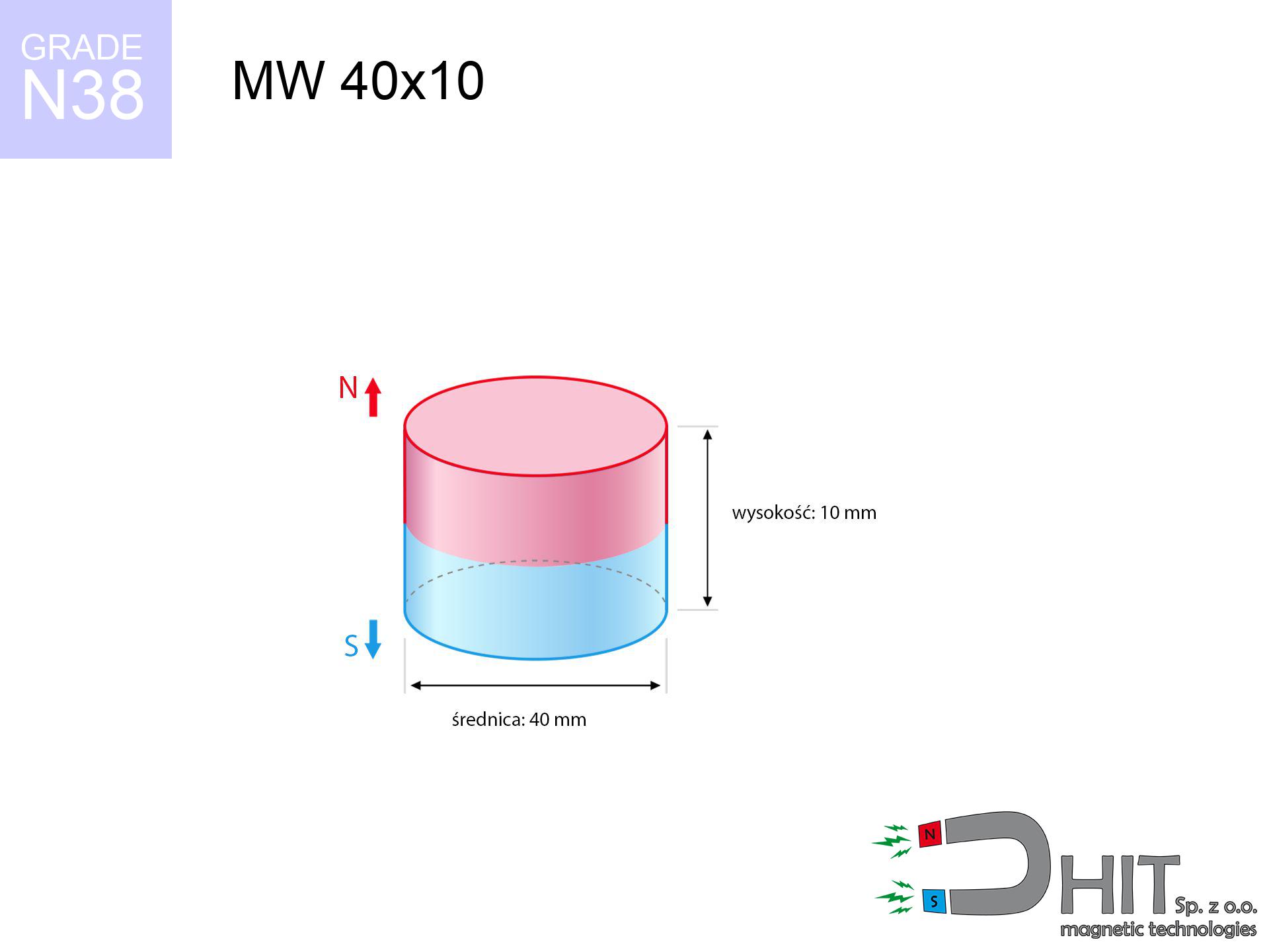
MW 40x10 / N38 - cylindrical magnet
cylindrical magnet
Catalog no 010066
GTIN/EAN: 5906301810650
- Diameter Ø
- 40 mm [±0,1 mm]
- Height
- 10 mm [±0,1 mm]
- Weight
- 94.25 g
- Magnetization Direction
- ↑ axial
- Coating
- [NiCuNi] Nickel
How we measure these parameters — certificates and measurements
29.73 zł net / pcs
36.57 zł with VAT (23% VAT) / pcs
bulk discounts:
Need more?Frequently asked questions
Where can I buy strong cylindrical neodymium magnets?
Can a small cylindrical magnet provide a strong grip for precise workshop work?
Which cylindrical magnet can work at a higher temperature?
Engineering report for this magnet
Full PDF analysis: pull and shear force, effect of distance, temperature and plate thickness, safety distances and the demagnetization curve.
Call us now
+48 888 99 98 98
alternatively let us know using
contact form
the contact section.
Specifications and structure of a neodymium magnet can be estimated using our
power calculator.
Order by 14:00 and we’ll ship today!
Technical details - MW 40x10 / N38 - cylindrical magnet
Specification / characteristics - MW 40x10 / N38 - cylindrical magnet
| properties | values |
|---|---|
| Cat. no. | 010066 |
| GTIN/EAN | 5906301810650 |
| Production/Distribution | Dhit sp. z o.o. |
| Country of origin | Poland / China / Germany |
| Customs code | 85059029 |
| Diameter Ø | 40 mm [±0,1 mm] |
| Height | 10 mm [±0,1 mm] |
| Weight | 94.25 g |
| Magnetization Direction | ↑ axial |
| Load capacity ~ ? | 27.73 kg / 271.99 N |
| Magnetic Induction ~ ? | 277.22 mT / 2772 Gs |
| Coating | [NiCuNi] Nickel |
| Manufacturing Tolerance | ±0.1 mm |
Magnetic properties of material N38
| properties | values | units |
|---|---|---|
| Remanence Br ? | 12.2-12.6 | kGs |
| Remanence Br ? | 1220-1260 | mT |
| Coercivity bHc ? | 10.8-11.5 | kOe |
| Coercivity bHc ? | 860-915 | kA/m |
| Intrinsic coercivity iHc | ≥ 12 | kOe |
| Intrinsic coercivity iHc | ≥ 955 | kA/m |
| Energy product BHmax ? | 36-38 | BH max MGOe |
| Energy product BHmax ? | 287-303 | BH max KJ/m |
| Maximum working temperature ? | ≤ 80 | °C |
Physical properties of sintered neodymium magnets Nd2Fe14B at 20°C
| properties | values | units |
|---|---|---|
| Vickers hardness | ≥550 | Hv |
| Density | ≥7.4 | g/cm3 |
| Curie Temperature TC | 310 | °C |
| Curie Temperature TF | 590 | °F |
| Specific resistance | 150 | μΩ⋅cm |
| Bending strength | 250 | MPa |
| Compressive strength | 1000~1100 | MPa |
| Thermal expansion parallel (∥) to orientation (M) | (3-4) x 10-6 | °C-1 |
| Thermal expansion perpendicular (⊥) to orientation (M) | -(1-3) x 10-6 | °C-1 |
| Young's modulus | 1.7 x 10⁴ | kg/mm² |
Technical analysis of the product - data
Presented data constitute the outcome of a physical analysis. Values rely on models for the class Nd2Fe14B. Operational parameters may deviate from the simulation results. Use these data as a reference point when designing systems.
Table 1: Static force (force vs distance) - interaction chart
MW 40x10 / N38
| Distance (mm) | Induction (Gauss) / mT | Pull Force (kg/lbs/g/N) | Risk Status |
|---|---|---|---|
| 0 mm |
2772 Gs
277.2 mT
|
27.73 kg / 61.13 lbs
27730.0 g / 272.0 N
|
dangerous! |
| 1 mm |
2678 Gs
267.8 mT
|
25.89 kg / 57.08 lbs
25889.6 g / 254.0 N
|
dangerous! |
| 2 mm |
2573 Gs
257.3 mT
|
23.89 kg / 52.68 lbs
23893.3 g / 234.4 N
|
dangerous! |
| 3 mm |
2459 Gs
245.9 mT
|
21.83 kg / 48.12 lbs
21827.6 g / 214.1 N
|
dangerous! |
| 5 mm |
2216 Gs
221.6 mT
|
17.73 kg / 39.08 lbs
17728.1 g / 173.9 N
|
dangerous! |
| 10 mm |
1611 Gs
161.1 mT
|
9.37 kg / 20.66 lbs
9371.0 g / 91.9 N
|
warning |
| 15 mm |
1121 Gs
112.1 mT
|
4.54 kg / 10.01 lbs
4538.6 g / 44.5 N
|
warning |
| 20 mm |
775 Gs
77.5 mT
|
2.17 kg / 4.77 lbs
2165.8 g / 21.2 N
|
warning |
| 30 mm |
387 Gs
38.7 mT
|
0.54 kg / 1.19 lbs
539.8 g / 5.3 N
|
weak grip |
| 50 mm |
125 Gs
12.5 mT
|
0.06 kg / 0.12 lbs
56.6 g / 0.6 N
|
weak grip |
Table 2: Vertical hold (wall)
MW 40x10 / N38
| Distance (mm) | Friction coefficient | Pull Force (kg/lbs/g/N) |
|---|---|---|
| 0 mm | Stal (~0.2) |
5.55 kg / 12.23 lbs
5546.0 g / 54.4 N
|
| 1 mm | Stal (~0.2) |
5.18 kg / 11.42 lbs
5178.0 g / 50.8 N
|
| 2 mm | Stal (~0.2) |
4.78 kg / 10.53 lbs
4778.0 g / 46.9 N
|
| 3 mm | Stal (~0.2) |
4.37 kg / 9.63 lbs
4366.0 g / 42.8 N
|
| 5 mm | Stal (~0.2) |
3.55 kg / 7.82 lbs
3546.0 g / 34.8 N
|
| 10 mm | Stal (~0.2) |
1.87 kg / 4.13 lbs
1874.0 g / 18.4 N
|
| 15 mm | Stal (~0.2) |
0.91 kg / 2.00 lbs
908.0 g / 8.9 N
|
| 20 mm | Stal (~0.2) |
0.43 kg / 0.96 lbs
434.0 g / 4.3 N
|
| 30 mm | Stal (~0.2) |
0.11 kg / 0.24 lbs
108.0 g / 1.1 N
|
| 50 mm | Stal (~0.2) |
0.01 kg / 0.03 lbs
12.0 g / 0.1 N
|
Table 3: Vertical assembly (shearing) - behavior on slippery surfaces
MW 40x10 / N38
| Surface type | Friction coefficient / % Mocy | Max load (kg/lbs/g/N) |
|---|---|---|
| Raw steel |
µ = 0.3
30% Nominalnej Siły
|
8.32 kg / 18.34 lbs
8319.0 g / 81.6 N
|
| Painted steel (standard) |
µ = 0.2
20% Nominalnej Siły
|
5.55 kg / 12.23 lbs
5546.0 g / 54.4 N
|
| Oily/slippery steel |
µ = 0.1
10% Nominalnej Siły
|
2.77 kg / 6.11 lbs
2773.0 g / 27.2 N
|
| Magnet with anti-slip rubber |
µ = 0.5
50% Nominalnej Siły
|
13.87 kg / 30.57 lbs
13865.0 g / 136.0 N
|
Table 4: Material efficiency (substrate influence) - sheet metal selection
MW 40x10 / N38
| Steel thickness (mm) | % power | Real pull force (kg/lbs/g/N) |
|---|---|---|
| 0.5 mm |
|
1.39 kg / 3.06 lbs
1386.5 g / 13.6 N
|
| 1 mm |
|
3.47 kg / 7.64 lbs
3466.3 g / 34.0 N
|
| 2 mm |
|
6.93 kg / 15.28 lbs
6932.5 g / 68.0 N
|
| 3 mm |
|
10.40 kg / 22.93 lbs
10398.8 g / 102.0 N
|
| 5 mm |
|
17.33 kg / 38.21 lbs
17331.3 g / 170.0 N
|
| 10 mm |
|
27.73 kg / 61.13 lbs
27730.0 g / 272.0 N
|
| 11 mm |
|
27.73 kg / 61.13 lbs
27730.0 g / 272.0 N
|
| 12 mm |
|
27.73 kg / 61.13 lbs
27730.0 g / 272.0 N
|
Table 5: Thermal resistance (stability) - power drop
MW 40x10 / N38
| Ambient temp. (°C) | Power loss | Remaining pull (kg/lbs/g/N) | Status |
|---|---|---|---|
| 20 °C | 0.0% |
27.73 kg / 61.13 lbs
27730.0 g / 272.0 N
|
OK |
| 40 °C | -2.2% |
27.12 kg / 59.79 lbs
27119.9 g / 266.0 N
|
OK |
| 60 °C | -4.4% |
26.51 kg / 58.44 lbs
26509.9 g / 260.1 N
|
|
| 80 °C | -6.6% |
25.90 kg / 57.10 lbs
25899.8 g / 254.1 N
|
|
| 100 °C | -28.8% |
19.74 kg / 43.53 lbs
19743.8 g / 193.7 N
|
Table 6: Two magnets (attraction) - forces in the system
MW 40x10 / N38
| Gap (mm) | Attraction (kg/lbs) (N-S) | Sliding Force (kg/lbs/g/N) | Repulsion (kg/lbs) (N-N) |
|---|---|---|---|
| 0 mm |
59.52 kg / 131.22 lbs
4 382 Gs
|
8.93 kg / 19.68 lbs
8928 g / 87.6 N
|
N/A |
| 1 mm |
57.61 kg / 127.01 lbs
5 454 Gs
|
8.64 kg / 19.05 lbs
8642 g / 84.8 N
|
51.85 kg / 114.31 lbs
~0 Gs
|
| 2 mm |
55.57 kg / 122.52 lbs
5 357 Gs
|
8.34 kg / 18.38 lbs
8336 g / 81.8 N
|
50.01 kg / 110.26 lbs
~0 Gs
|
| 3 mm |
53.46 kg / 117.85 lbs
5 254 Gs
|
8.02 kg / 17.68 lbs
8019 g / 78.7 N
|
48.11 kg / 106.07 lbs
~0 Gs
|
| 5 mm |
49.08 kg / 108.20 lbs
5 034 Gs
|
7.36 kg / 16.23 lbs
7362 g / 72.2 N
|
44.17 kg / 97.38 lbs
~0 Gs
|
| 10 mm |
38.05 kg / 83.89 lbs
4 433 Gs
|
5.71 kg / 12.58 lbs
5708 g / 56.0 N
|
34.25 kg / 75.50 lbs
~0 Gs
|
| 20 mm |
20.11 kg / 44.35 lbs
3 223 Gs
|
3.02 kg / 6.65 lbs
3017 g / 29.6 N
|
18.10 kg / 39.91 lbs
~0 Gs
|
| 50 mm |
2.27 kg / 5.01 lbs
1 083 Gs
|
0.34 kg / 0.75 lbs
341 g / 3.3 N
|
2.05 kg / 4.51 lbs
~0 Gs
|
| 60 mm |
1.16 kg / 2.55 lbs
773 Gs
|
0.17 kg / 0.38 lbs
174 g / 1.7 N
|
1.04 kg / 2.30 lbs
~0 Gs
|
| 70 mm |
0.62 kg / 1.36 lbs
565 Gs
|
0.09 kg / 0.20 lbs
93 g / 0.9 N
|
0.56 kg / 1.23 lbs
~0 Gs
|
| 80 mm |
0.35 kg / 0.76 lbs
422 Gs
|
0.05 kg / 0.11 lbs
52 g / 0.5 N
|
0.31 kg / 0.69 lbs
~0 Gs
|
| 90 mm |
0.20 kg / 0.44 lbs
322 Gs
|
0.03 kg / 0.07 lbs
30 g / 0.3 N
|
0.18 kg / 0.40 lbs
~0 Gs
|
| 100 mm |
0.12 kg / 0.27 lbs
251 Gs
|
0.02 kg / 0.04 lbs
18 g / 0.2 N
|
0.11 kg / 0.24 lbs
~0 Gs
|
Table 7: Protective zones (implants) - precautionary measures
MW 40x10 / N38
| Object / Device | Limit (Gauss) / mT | Safe distance |
|---|---|---|
| Pacemaker | 5 Gs (0.5 mT) | 16.5 cm |
| Hearing aid | 10 Gs (1.0 mT) | 13.0 cm |
| Timepiece | 20 Gs (2.0 mT) | 10.5 cm |
| Mobile device | 40 Gs (4.0 mT) | 8.0 cm |
| Car key | 50 Gs (5.0 mT) | 7.5 cm |
| Payment card | 400 Gs (40.0 mT) | 3.0 cm |
| HDD hard drive | 600 Gs (60.0 mT) | 2.5 cm |
Table 8: Collisions (cracking risk) - collision effects
MW 40x10 / N38
| Start from (mm) | Speed (km/h) | Energy (J) | Predicted outcome |
|---|---|---|---|
| 10 mm |
22.06 km/h
(6.13 m/s)
|
1.77 J | |
| 30 mm |
25.52 km/h
(7.09 m/s)
|
2.37 J | |
| 50 mm |
25.74 km/h
(7.15 m/s)
|
2.41 J | |
| 100 mm |
25.77 km/h
(7.16 m/s)
|
2.41 J |
Table 9: Corrosion resistance
MW 40x10 / N38
| Technical parameter | Value / Description |
|---|---|
| Coating type | [NiCuNi] Nickel |
| Layer structure | Nickel - Copper - Nickel |
| Layer thickness | 10-20 µm |
| Salt spray test (SST) ? | 24 h |
| Recommended environment | Indoors only (dry) |
Table 10: Electrical data (Flux)
MW 40x10 / N38
| Parameter | Value | SI Unit / Description |
|---|---|---|
| Magnetic Flux | 38 700 Mx | 387.0 µWb |
| Pc Coefficient | 0.35 | Low (Flat) |
Table 11: Hydrostatics and buoyancy
MW 40x10 / N38
| Environment | Effective steel pull | Effect |
|---|---|---|
| Air (land) | 27.73 kg | Standard |
| Water (riverbed) |
31.75 kg
(+4.02 kg buoyancy gain)
|
+14.5% |
1. Wall mount (shear)
*Caution: On a vertical surface, the magnet holds just ~20% of its nominal pull.
2. Steel thickness impact
*Thin metal sheet (e.g. computer case) drastically weakens the holding force.
3. Heat tolerance
N38: the maximum material working temperature is 80°C. Permitted conditions also depend on the shape and magnetic circuit.
4. Demagnetization curve and operating point (B-H)
chart generated for the permeance coefficient Pc (Permeance Coefficient) = 0.35
This simulation demonstrates the magnetic stability of the selected magnet under specific geometric conditions. The solid red line represents the demagnetization curve (material potential), while the dashed blue line is the load line based on the magnet's geometry. The Pc (Permeance Coefficient), also known as the load line slope, is a dimensionless value that describes the relationship between the magnet's shape and its magnetic stability. The intersection of these two lines (the black dot) is the operating point — it determines the actual magnetic flux density generated by the magnet in this specific configuration. A higher Pc value means the magnet is more 'slender' (tall relative to its area), resulting in a higher operating point and better resistance to irreversible demagnetization caused by external fields or temperature. A value of 0.42 is relatively low (typical for flat magnets), meaning the operating point is closer to the 'knee' of the curve — caution is advised when operating at temperatures near the maximum limit to avoid strength loss.
Elemental analysis
| iron (Fe) | 64% – 68% |
| neodymium (Nd) | 29% – 32% |
| boron (B) | 1.1% – 1.2% |
| dysprosium (Dy) | 0.5% – 2.0% |
| coating (Ni-Cu-Ni) | < 0.05% |
Environmental data
| recyclability (EoL) | 100% |
| recycled raw materials | ~10% (pre-cons) |
| carbon footprint | low / zredukowany |
| waste code (EWC) | 16 02 16 |
Other products
![UMH 48x11x65 [M6] / N38 - magnetic holder with hook](https://cdn3.dhit.pl/graphics/products/umh-48x11x65-m6-wiw.jpg "UMH 48x11x65 [M6] / N38 - magnetic holder with hook")
Pros as well as cons of Nd2Fe14B magnets.
Pros
- They do not lose strength, even during approximately ten years – the drop in lifting capacity is only ~1% (according to tests),
- Magnets very well protect themselves against demagnetization caused by external fields,
- The use of an metallic layer of noble metals (nickel, gold, silver) causes the element to present itself better,
- They feature high magnetic induction at the operating surface, making them more effective,
- Through (appropriate) combination of ingredients, they can achieve high thermal resistance, allowing for functioning at temperatures reaching 230°C and above...
- Possibility of detailed shaping and adjusting to precise applications,
- Significant place in high-tech industry – they find application in computer drives, motor assemblies, precision medical tools, as well as complex engineering applications.
- Compactness – despite small sizes they provide effective action, making them ideal for precision applications
Limitations
- They are fragile upon too strong impacts. To avoid cracks, it is worth protecting magnets using a steel holder. Such protection not only shields the magnet but also improves its resistance to damage
- Do not exceed this material temperature limit: 80°C. Overheating may permanently weaken the magnet.
- When exposed to humidity, magnets usually rust. To use them in conditions outside, it is recommended to use protective magnets, such as those in rubber or plastics, which secure oxidation as well as corrosion.
- Limited ability of producing threads in the magnet and complicated shapes - preferred is cover - magnet mounting.
- Possible danger resulting from small fragments of magnets are risky, in case of ingestion, which becomes key in the aspect of protecting the youngest. It is also worth noting that tiny parts of these devices can complicate diagnosis medical in case of swallowing.
- With large orders the cost of neodymium magnets can be a barrier,
Pull force analysis
Breakaway strength of the magnet in ideal conditions – what affects it?
- using a base made of high-permeability steel, functioning as a circuit closing element
- whose thickness reaches at least 10 mm
- with an polished touching surface
- under conditions of ideal adhesion (metal-to-metal)
- for force acting at a right angle (in the magnet axis)
- at standard ambient temperature
Magnet lifting force in use – key factors
- Distance (betwixt the magnet and the plate), since even a microscopic distance (e.g. 0.5 mm) leads to a decrease in lifting capacity by up to 50% (this also applies to paint, corrosion or dirt).
- Loading method – declared lifting capacity refers to pulling vertically. When attempting to slide, the magnet exhibits significantly lower power (typically approx. 20-30% of maximum force).
- Element thickness – to utilize 100% power, the steel must be adequately massive. Paper-thin metal restricts the lifting capacity (the magnet "punches through" it).
- Material type – the best choice is high-permeability steel. Hardened steels may attract less.
- Surface condition – ground elements guarantee perfect abutment, which improves field saturation. Uneven metal weaken the grip.
- Thermal factor – high temperature reduces pulling force. Too high temperature can permanently demagnetize the magnet.
Holding force was measured on a smooth steel plate of 20 mm thickness, when a perpendicular force was applied, in contrast under attempts to slide the magnet the holding force is lower. Additionally, even a minimal clearance between the magnet’s surface and the plate lowers the holding force.
Precautions when working with NdFeB magnets
Heat sensitivity
Keep cool. NdFeB magnets are susceptible to heat. If you need operation above 80°C, ask us about special high-temperature series (H, SH, UH).
Adults only
Only for adults. Tiny parts can be swallowed, leading to intestinal necrosis. Store away from children and animals.
Threat to electronics
Avoid bringing magnets close to a purse, computer, or TV. The magnetic field can destroy these devices and erase data from cards.
Serious injuries
Danger of trauma: The pulling power is so great that it can result in blood blisters, crushing, and broken bones. Protective gloves are recommended.
Implant safety
Individuals with a ICD should maintain an large gap from magnets. The magnetic field can disrupt the operation of the implant.
Flammability
Powder produced during machining of magnets is self-igniting. Avoid drilling into magnets without proper cooling and knowledge.
Allergic reactions
Nickel alert: The Ni-Cu-Ni coating consists of nickel. If redness appears, cease working with magnets and use protective gear.
Precision electronics
Be aware: neodymium magnets produce a field that confuses sensitive sensors. Keep a separation from your mobile, device, and GPS.
Respect the power
Before starting, read the rules. Sudden snapping can break the magnet or hurt your hand. Be predictive.
Fragile material
NdFeB magnets are sintered ceramics, meaning they are very brittle. Clashing of two magnets leads to them cracking into small pieces.
Tabela kosztu i czasu dostawy
Płatność przed wysyłką:

GLS kurier
Przesyłka będzie u Ciebie za 2-3 dni
14.99 ZŁ

InPost Paczkomaty 24/7
Przesyłka będzie u Ciebie za 1-2 dni
12.30 ZŁ
Płatność przy odbiorze (pobranie):
GLS kurier
Przesyłka będzie u Ciebie za 1-2 dni
23.00 ZŁ