

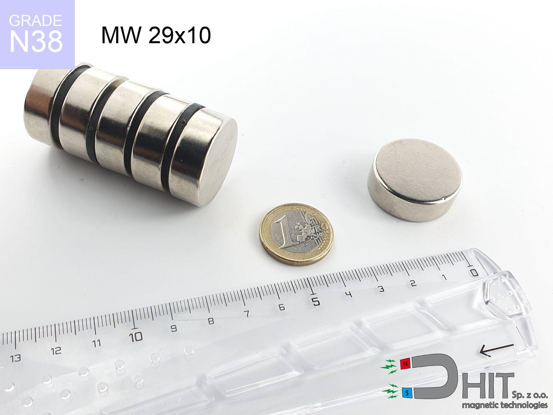
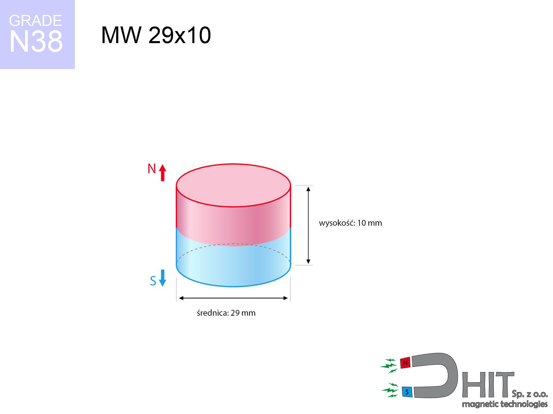
MW 29x10 / N38 - cylindrical magnet
cylindrical magnet
Catalog no 010053
GTIN/EAN: 5906301810520
- Diameter Ø
- 29 mm [±0,1 mm]
- Height
- 10 mm [±0,1 mm]
- Weight
- 49.54 g
- Magnetization Direction
- ↑ axial
- Coating
- [NiCuNi] Nickel
How we measure these parameters — certificates and measurements
14.10 zł net / pcs
17.34 zł with VAT (23% VAT) / pcs
bulk discounts:
Need more?Frequently asked questions
Where can I buy strong cylindrical neodymium magnets?
Can a small cylindrical magnet provide a strong grip for precise workshop work?
Which cylindrical magnet can work at a higher temperature?
Engineering report for this magnet
Full PDF analysis: pull and shear force, effect of distance, temperature and plate thickness, safety distances and the demagnetization curve.
Call us now
+48 888 99 98 98
alternatively let us know using
contact form
the contact section.
Specifications and structure of a neodymium magnet can be estimated using our
power calculator.
Order by 14:00 and we’ll ship today!
Technical data of the product - MW 29x10 / N38 - cylindrical magnet
Specification / characteristics - MW 29x10 / N38 - cylindrical magnet
| properties | values |
|---|---|
| Cat. no. | 010053 |
| GTIN/EAN | 5906301810520 |
| Production/Distribution | Dhit sp. z o.o. |
| Country of origin | Poland / China / Germany |
| Customs code | 85059029 |
| Diameter Ø | 29 mm [±0,1 mm] |
| Height | 10 mm [±0,1 mm] |
| Weight | 49.54 g |
| Magnetization Direction | ↑ axial |
| Load capacity ~ ? | 20.82 kg / 204.22 N |
| Magnetic Induction ~ ? | 351.88 mT / 3519 Gs |
| Coating | [NiCuNi] Nickel |
| Manufacturing Tolerance | ±0.1 mm |
Magnetic properties of material N38
| properties | values | units |
|---|---|---|
| Remanence Br ? | 12.2-12.6 | kGs |
| Remanence Br ? | 1220-1260 | mT |
| Coercivity bHc ? | 10.8-11.5 | kOe |
| Coercivity bHc ? | 860-915 | kA/m |
| Intrinsic coercivity iHc | ≥ 12 | kOe |
| Intrinsic coercivity iHc | ≥ 955 | kA/m |
| Energy product BHmax ? | 36-38 | BH max MGOe |
| Energy product BHmax ? | 287-303 | BH max KJ/m |
| Maximum working temperature ? | ≤ 80 | °C |
Physical properties of sintered neodymium magnets Nd2Fe14B at 20°C
| properties | values | units |
|---|---|---|
| Vickers hardness | ≥550 | Hv |
| Density | ≥7.4 | g/cm3 |
| Curie Temperature TC | 310 | °C |
| Curie Temperature TF | 590 | °F |
| Specific resistance | 150 | μΩ⋅cm |
| Bending strength | 250 | MPa |
| Compressive strength | 1000~1100 | MPa |
| Thermal expansion parallel (∥) to orientation (M) | (3-4) x 10-6 | °C-1 |
| Thermal expansion perpendicular (⊥) to orientation (M) | -(1-3) x 10-6 | °C-1 |
| Young's modulus | 1.7 x 10⁴ | kg/mm² |
Technical simulation of the magnet - data
The following values constitute the result of a mathematical analysis. Results were calculated on algorithms for the material Nd2Fe14B. Real-world conditions might slightly differ. Treat these calculations as a preliminary roadmap when designing systems.
Table 1: Static force (pull vs distance) - power drop
MW 29x10 / N38
| Distance (mm) | Induction (Gauss) / mT | Pull Force (kg/lbs/g/N) | Risk Status |
|---|---|---|---|
| 0 mm |
3518 Gs
351.8 mT
|
20.82 kg / 45.90 pounds
20820.0 g / 204.2 N
|
crushing |
| 1 mm |
3321 Gs
332.1 mT
|
18.55 kg / 40.89 pounds
18548.8 g / 182.0 N
|
crushing |
| 2 mm |
3106 Gs
310.6 mT
|
16.23 kg / 35.77 pounds
16226.1 g / 159.2 N
|
crushing |
| 3 mm |
2883 Gs
288.3 mT
|
13.98 kg / 30.82 pounds
13978.2 g / 137.1 N
|
crushing |
| 5 mm |
2437 Gs
243.7 mT
|
9.99 kg / 22.02 pounds
9987.1 g / 98.0 N
|
strong |
| 10 mm |
1500 Gs
150.0 mT
|
3.78 kg / 8.34 pounds
3783.1 g / 37.1 N
|
strong |
| 15 mm |
905 Gs
90.5 mT
|
1.38 kg / 3.04 pounds
1379.2 g / 13.5 N
|
low risk |
| 20 mm |
563 Gs
56.3 mT
|
0.53 kg / 1.17 pounds
532.4 g / 5.2 N
|
low risk |
| 30 mm |
247 Gs
24.7 mT
|
0.10 kg / 0.23 pounds
102.4 g / 1.0 N
|
low risk |
| 50 mm |
72 Gs
7.2 mT
|
0.01 kg / 0.02 pounds
8.7 g / 0.1 N
|
low risk |
Table 2: Vertical capacity (wall)
MW 29x10 / N38
| Distance (mm) | Friction coefficient | Pull Force (kg/lbs/g/N) |
|---|---|---|
| 0 mm | Stal (~0.2) |
4.16 kg / 9.18 pounds
4164.0 g / 40.8 N
|
| 1 mm | Stal (~0.2) |
3.71 kg / 8.18 pounds
3710.0 g / 36.4 N
|
| 2 mm | Stal (~0.2) |
3.25 kg / 7.16 pounds
3246.0 g / 31.8 N
|
| 3 mm | Stal (~0.2) |
2.80 kg / 6.16 pounds
2796.0 g / 27.4 N
|
| 5 mm | Stal (~0.2) |
2.00 kg / 4.40 pounds
1998.0 g / 19.6 N
|
| 10 mm | Stal (~0.2) |
0.76 kg / 1.67 pounds
756.0 g / 7.4 N
|
| 15 mm | Stal (~0.2) |
0.28 kg / 0.61 pounds
276.0 g / 2.7 N
|
| 20 mm | Stal (~0.2) |
0.11 kg / 0.23 pounds
106.0 g / 1.0 N
|
| 30 mm | Stal (~0.2) |
0.02 kg / 0.04 pounds
20.0 g / 0.2 N
|
| 50 mm | Stal (~0.2) |
0.00 kg / 0.00 pounds
2.0 g / 0.0 N
|
Table 3: Vertical assembly (shearing) - vertical pull
MW 29x10 / N38
| Surface type | Friction coefficient / % Mocy | Max load (kg/lbs/g/N) |
|---|---|---|
| Raw steel |
µ = 0.3
30% Nominalnej Siły
|
6.25 kg / 13.77 pounds
6246.0 g / 61.3 N
|
| Painted steel (standard) |
µ = 0.2
20% Nominalnej Siły
|
4.16 kg / 9.18 pounds
4164.0 g / 40.8 N
|
| Oily/slippery steel |
µ = 0.1
10% Nominalnej Siły
|
2.08 kg / 4.59 pounds
2082.0 g / 20.4 N
|
| Magnet with anti-slip rubber |
µ = 0.5
50% Nominalnej Siły
|
10.41 kg / 22.95 pounds
10410.0 g / 102.1 N
|
Table 4: Steel thickness (substrate influence) - power losses
MW 29x10 / N38
| Steel thickness (mm) | % power | Real pull force (kg/lbs/g/N) |
|---|---|---|
| 0.5 mm |
|
1.04 kg / 2.30 pounds
1041.0 g / 10.2 N
|
| 1 mm |
|
2.60 kg / 5.74 pounds
2602.5 g / 25.5 N
|
| 2 mm |
|
5.21 kg / 11.48 pounds
5205.0 g / 51.1 N
|
| 3 mm |
|
7.81 kg / 17.21 pounds
7807.5 g / 76.6 N
|
| 5 mm |
|
13.01 kg / 28.69 pounds
13012.5 g / 127.7 N
|
| 10 mm |
|
20.82 kg / 45.90 pounds
20820.0 g / 204.2 N
|
| 11 mm |
|
20.82 kg / 45.90 pounds
20820.0 g / 204.2 N
|
| 12 mm |
|
20.82 kg / 45.90 pounds
20820.0 g / 204.2 N
|
Table 5: Thermal stability (stability) - power drop
MW 29x10 / N38
| Ambient temp. (°C) | Power loss | Remaining pull (kg/lbs/g/N) | Status |
|---|---|---|---|
| 20 °C | 0.0% |
20.82 kg / 45.90 pounds
20820.0 g / 204.2 N
|
OK |
| 40 °C | -2.2% |
20.36 kg / 44.89 pounds
20362.0 g / 199.8 N
|
OK |
| 60 °C | -4.4% |
19.90 kg / 43.88 pounds
19903.9 g / 195.3 N
|
|
| 80 °C | -6.6% |
19.45 kg / 42.87 pounds
19445.9 g / 190.8 N
|
|
| 100 °C | -28.8% |
14.82 kg / 32.68 pounds
14823.8 g / 145.4 N
|
Table 6: Magnet-Magnet interaction (attraction) - forces in the system
MW 29x10 / N38
| Gap (mm) | Attraction (kg/lbs) (N-S) | Sliding Force (kg/lbs/g/N) | Repulsion (kg/lbs) (N-N) |
|---|---|---|---|
| 0 mm |
50.40 kg / 111.11 pounds
5 016 Gs
|
7.56 kg / 16.67 pounds
7560 g / 74.2 N
|
N/A |
| 1 mm |
47.70 kg / 105.17 pounds
6 845 Gs
|
7.16 kg / 15.78 pounds
7156 g / 70.2 N
|
42.93 kg / 94.65 pounds
~0 Gs
|
| 2 mm |
44.90 kg / 98.99 pounds
6 641 Gs
|
6.74 kg / 14.85 pounds
6735 g / 66.1 N
|
40.41 kg / 89.09 pounds
~0 Gs
|
| 3 mm |
42.08 kg / 92.77 pounds
6 429 Gs
|
6.31 kg / 13.92 pounds
6312 g / 61.9 N
|
37.87 kg / 83.50 pounds
~0 Gs
|
| 5 mm |
36.52 kg / 80.52 pounds
5 990 Gs
|
5.48 kg / 12.08 pounds
5478 g / 53.7 N
|
32.87 kg / 72.47 pounds
~0 Gs
|
| 10 mm |
24.18 kg / 53.30 pounds
4 873 Gs
|
3.63 kg / 7.99 pounds
3626 g / 35.6 N
|
21.76 kg / 47.97 pounds
~0 Gs
|
| 20 mm |
9.16 kg / 20.19 pounds
2 999 Gs
|
1.37 kg / 3.03 pounds
1374 g / 13.5 N
|
8.24 kg / 18.17 pounds
~0 Gs
|
| 50 mm |
0.54 kg / 1.19 pounds
729 Gs
|
0.08 kg / 0.18 pounds
81 g / 0.8 N
|
0.49 kg / 1.07 pounds
~0 Gs
|
| 60 mm |
0.25 kg / 0.55 pounds
493 Gs
|
0.04 kg / 0.08 pounds
37 g / 0.4 N
|
0.22 kg / 0.49 pounds
~0 Gs
|
| 70 mm |
0.12 kg / 0.27 pounds
347 Gs
|
0.02 kg / 0.04 pounds
18 g / 0.2 N
|
0.11 kg / 0.24 pounds
~0 Gs
|
| 80 mm |
0.06 kg / 0.14 pounds
252 Gs
|
0.01 kg / 0.02 pounds
10 g / 0.1 N
|
0.06 kg / 0.13 pounds
~0 Gs
|
| 90 mm |
0.04 kg / 0.08 pounds
188 Gs
|
0.01 kg / 0.01 pounds
5 g / 0.1 N
|
0.03 kg / 0.07 pounds
~0 Gs
|
| 100 mm |
0.02 kg / 0.05 pounds
144 Gs
|
0.00 kg / 0.01 pounds
3 g / 0.0 N
|
0.02 kg / 0.04 pounds
~0 Gs
|
Table 7: Safety (HSE) (implants) - warnings
MW 29x10 / N38
| Object / Device | Limit (Gauss) / mT | Safe distance |
|---|---|---|
| Pacemaker | 5 Gs (0.5 mT) | 13.5 cm |
| Hearing aid | 10 Gs (1.0 mT) | 10.5 cm |
| Timepiece | 20 Gs (2.0 mT) | 8.5 cm |
| Mobile device | 40 Gs (4.0 mT) | 6.5 cm |
| Remote | 50 Gs (5.0 mT) | 6.0 cm |
| Payment card | 400 Gs (40.0 mT) | 2.5 cm |
| HDD hard drive | 600 Gs (60.0 mT) | 2.0 cm |
Table 8: Dynamics (cracking risk) - collision effects
MW 29x10 / N38
| Start from (mm) | Speed (km/h) | Energy (J) | Predicted outcome |
|---|---|---|---|
| 10 mm |
23.58 km/h
(6.55 m/s)
|
1.06 J | |
| 30 mm |
25.55 km/h
(7.10 m/s)
|
1.25 J | |
| 50 mm |
25.62 km/h
(7.12 m/s)
|
1.25 J | |
| 100 mm |
25.63 km/h
(7.12 m/s)
|
1.26 J |
Table 9: Corrosion resistance
MW 29x10 / N38
| Technical parameter | Value / Description |
|---|---|
| Coating type | [NiCuNi] Nickel |
| Layer structure | Nickel - Copper - Nickel |
| Layer thickness | 10-20 µm |
| Salt spray test (SST) ? | 24 h |
| Recommended environment | Indoors only (dry) |
Table 10: Electrical data (Flux)
MW 29x10 / N38
| Parameter | Value | SI Unit / Description |
|---|---|---|
| Magnetic Flux | 24 471 Mx | 244.7 µWb |
| Pc Coefficient | 0.45 | Low (Flat) |
Table 11: Hydrostatics and buoyancy
MW 29x10 / N38
| Environment | Effective steel pull | Effect |
|---|---|---|
| Air (land) | 20.82 kg | Standard |
| Water (riverbed) |
23.84 kg
(+3.02 kg buoyancy gain)
|
+14.5% |
1. Sliding resistance
*Warning: On a vertical wall, the magnet retains only approx. 20-30% of its nominal pull.
2. Steel saturation
*Thin metal sheet (e.g. computer case) significantly reduces the holding force.
3. Heat tolerance
N38: the maximum material working temperature is 80°C. Permitted conditions also depend on the shape and magnetic circuit.
4. Demagnetization curve and operating point (B-H)
chart generated for the permeance coefficient Pc (Permeance Coefficient) = 0.45
This simulation demonstrates the magnetic stability of the selected magnet under specific geometric conditions. The solid red line represents the demagnetization curve (material potential), while the dashed blue line is the load line based on the magnet's geometry. The Pc (Permeance Coefficient), also known as the load line slope, is a dimensionless value that describes the relationship between the magnet's shape and its magnetic stability. The intersection of these two lines (the black dot) is the operating point — it determines the actual magnetic flux density generated by the magnet in this specific configuration. A higher Pc value means the magnet is more 'slender' (tall relative to its area), resulting in a higher operating point and better resistance to irreversible demagnetization caused by external fields or temperature. A value of 0.42 is relatively low (typical for flat magnets), meaning the operating point is closer to the 'knee' of the curve — caution is advised when operating at temperatures near the maximum limit to avoid strength loss.
Elemental analysis
| iron (Fe) | 64% – 68% |
| neodymium (Nd) | 29% – 32% |
| boron (B) | 1.1% – 1.2% |
| dysprosium (Dy) | 0.5% – 2.0% |
| coating (Ni-Cu-Ni) | < 0.05% |
Environmental data
| recyclability (EoL) | 100% |
| recycled raw materials | ~10% (pre-cons) |
| carbon footprint | low / zredukowany |
| waste code (EWC) | 16 02 16 |
See more proposals

![SM 32x125 [2xM8] / N52 - magnetic separator](https://cdn3.dhit.pl/graphics/products/sm-32x125-2xm8-moj.jpg "SM 32x125 [2xM8] / N52 - magnetic separator")

![SM 32x400 [2xM8] / N42 - magnetic separator](https://cdn3.dhit.pl/graphics/products/sm-32x400-2xm8-tep.jpg "SM 32x400 [2xM8] / N42 - magnetic separator")
Strengths as well as weaknesses of Nd2Fe14B magnets.
Pros
- They have unchanged lifting capacity, and over more than ten years their attraction force decreases symbolically – ~1% (according to theory),
- They retain their magnetic properties even under external field action,
- In other words, due to the glossy finish of nickel, the element is aesthetically pleasing,
- They are known for high magnetic induction at the operating surface, which improves attraction properties,
- Neodymium magnets are characterized by extremely high magnetic induction on the magnet surface and can work (depending on the form) even at a temperature of 230°C or more...
- Possibility of precise modeling and adjusting to specific needs,
- Universal use in electronics industry – they are utilized in magnetic memories, electric drive systems, advanced medical instruments, and modern systems.
- Relatively small size with high pulling force – neodymium magnets offer impressive pulling force in compact dimensions, which makes them useful in small systems
Disadvantages
- They are fragile upon too strong impacts. To avoid cracks, it is worth securing magnets in a protective case. Such protection not only shields the magnet but also improves its resistance to damage
- Do not exceed this material temperature limit: 80°C. Overheating may permanently weaken the magnet.
- They oxidize in a humid environment - during use outdoors we recommend using waterproof magnets e.g. in rubber, plastic
- Limited possibility of making threads in the magnet and complex shapes - preferred is cover - mounting mechanism.
- Potential hazard resulting from small fragments of magnets can be dangerous, when accidentally swallowed, which gains importance in the context of child health protection. Additionally, small components of these devices can complicate diagnosis medical when they are in the body.
- With mass production the cost of neodymium magnets is a challenge,
Lifting parameters
Maximum lifting force for a neodymium magnet – what contributes to it?
- using a plate made of mild steel, acting as a ideal flux conductor
- whose transverse dimension equals approx. 10 mm
- characterized by smoothness
- under conditions of gap-free contact (surface-to-surface)
- for force acting at a right angle (in the magnet axis)
- in stable room temperature
Impact of factors on magnetic holding capacity in practice
- Gap (between the magnet and the plate), because even a microscopic clearance (e.g. 0.5 mm) results in a decrease in lifting capacity by up to 50% (this also applies to varnish, corrosion or dirt).
- Pull-off angle – remember that the magnet holds strongest perpendicularly. Under sliding down, the holding force drops significantly, often to levels of 20-30% of the nominal value.
- Wall thickness – the thinner the sheet, the weaker the hold. Magnetic flux penetrates through instead of converting into lifting capacity.
- Metal type – different alloys reacts the same. High carbon content weaken the attraction effect.
- Smoothness – full contact is obtained only on polished steel. Rough texture create air cushions, reducing force.
- Temperature – heating the magnet results in weakening of induction. It is worth remembering the maximum operating temperature for a given model.
Lifting capacity testing was carried out on plates with a smooth surface of suitable thickness, under perpendicular forces, in contrast under attempts to slide the magnet the load capacity is reduced by as much as 75%. Moreover, even a minimal clearance between the magnet’s surface and the plate lowers the holding force.
Precautions when working with NdFeB magnets
Crushing risk
Protect your hands. Two large magnets will join immediately with a force of massive weight, crushing anything in their path. Be careful!
Fire risk
Dust generated during machining of magnets is combustible. Avoid drilling into magnets unless you are an expert.
Shattering risk
Protect your eyes. Magnets can explode upon violent connection, launching sharp fragments into the air. We recommend safety glasses.
Choking Hazard
Strictly store magnets away from children. Choking hazard is high, and the consequences of magnets connecting inside the body are fatal.
Electronic hazard
Data protection: Neodymium magnets can damage data carriers and delicate electronics (pacemakers, medical aids, mechanical watches).
Heat warning
Keep cool. NdFeB magnets are susceptible to heat. If you require operation above 80°C, inquire about special high-temperature series (H, SH, UH).
Powerful field
Before use, read the rules. Sudden snapping can destroy the magnet or injure your hand. Be predictive.
Warning for heart patients
For implant holders: Strong magnetic fields disrupt medical devices. Keep at least 30 cm distance or request help to work with the magnets.
Compass and GPS
Navigation devices and mobile phones are extremely susceptible to magnetic fields. Close proximity with a powerful NdFeB magnet can decalibrate the internal compass in your phone.
Metal Allergy
Nickel alert: The nickel-copper-nickel coating consists of nickel. If redness appears, cease working with magnets and wear gloves.
Tabela kosztu i czasu dostawy
Płatność przed wysyłką:

GLS kurier
Przesyłka będzie u Ciebie za 2-3 dni
14.99 ZŁ

InPost Paczkomaty 24/7
Przesyłka będzie u Ciebie za 1-2 dni
12.30 ZŁ
Płatność przy odbiorze (pobranie):
GLS kurier
Przesyłka będzie u Ciebie za 1-2 dni
23.00 ZŁ