

MW 18x2 / N38 - cylindrical magnet
cylindrical magnet
Catalog no 010592
GTIN/EAN: 5906301815860
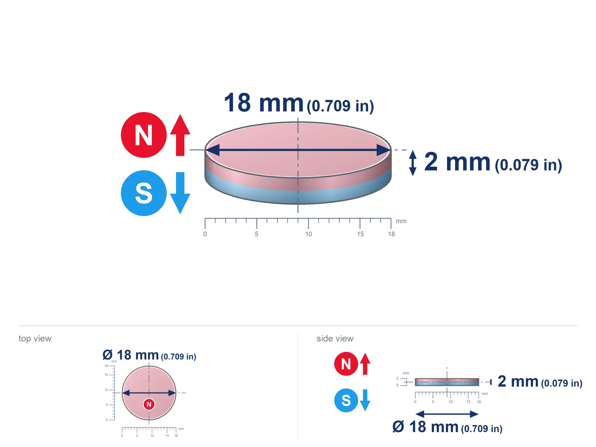
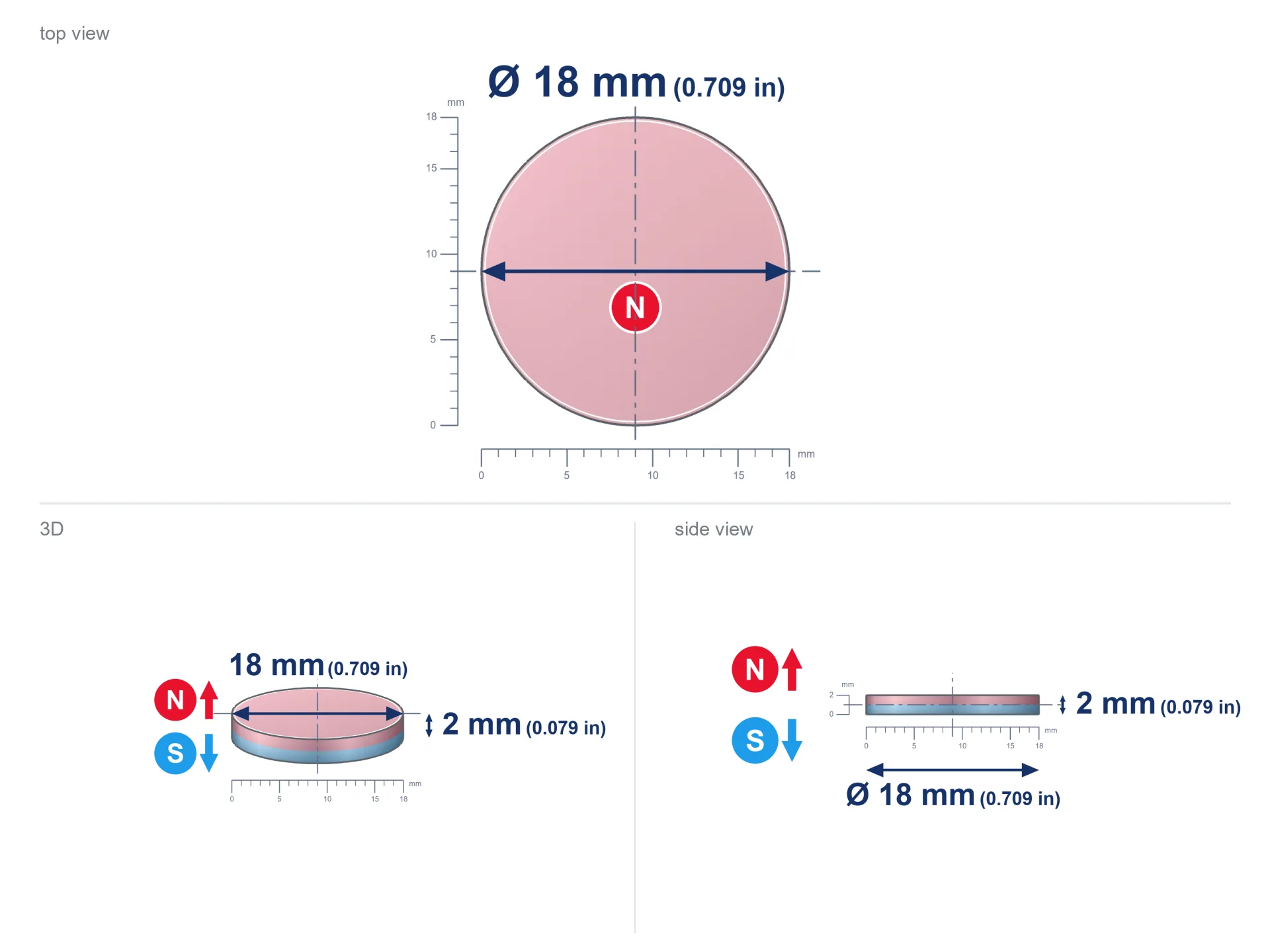
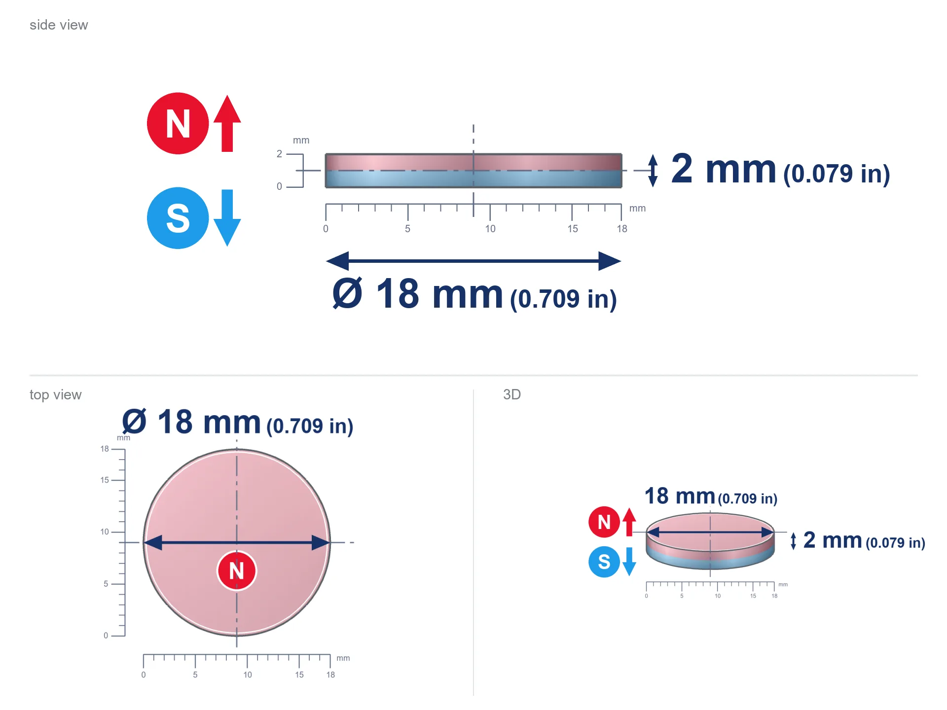
- Diameter Ø
- 18 mm [±0,1 mm]
- Height
- 2 mm [±0,1 mm]
- Weight
- 3.82 g
- Magnetization Direction
- ↑ axial
- Coating
- [NiCuNi] Nickel
How we measure these parameters — certificates and measurements
1.730 zł net / pcs
2.13 zł with VAT (23% VAT) / pcs
bulk discounts:
Need more?Frequently asked questions
Where can I buy strong cylindrical neodymium magnets?
Can a small cylindrical magnet provide a strong grip for precise workshop work?
Which cylindrical magnet can work at a higher temperature?
Engineering report for this magnet
Full PDF analysis: pull and shear force, effect of distance, temperature and plate thickness, safety distances and the demagnetization curve.
Call us now
+48 888 99 98 98
alternatively let us know using
contact form
the contact section.
Specifications and structure of a neodymium magnet can be estimated using our
power calculator.
Order by 14:00 and we’ll ship today!
Technical parameters of the product - MW 18x2 / N38 - cylindrical magnet
Specification / characteristics - MW 18x2 / N38 - cylindrical magnet
| properties | values |
|---|---|
| Cat. no. | 010592 |
| GTIN/EAN | 5906301815860 |
| Distributor | Dhit sp. z o.o. |
| Country of origin | Poland / China / Germany |
| Customs code | 85059029 |
| Diameter Ø | 18 mm [±0,1 mm] |
| Height | 2 mm [±0,1 mm] |
| Weight | 3.82 g |
| Magnetization Direction | ↑ axial |
| Load capacity ~ ? | 1.58 kg / 15.49 N |
| Magnetic Induction ~ ? | 134.47 mT / 1345 Gs |
| Coating | [NiCuNi] Nickel |
| Manufacturing Tolerance | ±0.1 mm |
Magnetic properties of material N38
| properties | values | units |
|---|---|---|
| Remanence Br ? | 12.2-12.6 | kGs |
| Remanence Br ? | 1220-1260 | mT |
| Coercivity bHc ? | 10.8-11.5 | kOe |
| Coercivity bHc ? | 860-915 | kA/m |
| Intrinsic coercivity iHc | ≥ 12 | kOe |
| Intrinsic coercivity iHc | ≥ 955 | kA/m |
| Energy product BHmax ? | 36-38 | BH max MGOe |
| Energy product BHmax ? | 287-303 | BH max KJ/m |
| Maximum working temperature ? | ≤ 80 | °C |
Physical properties of sintered neodymium magnets Nd2Fe14B at 20°C
| properties | values | units |
|---|---|---|
| Vickers hardness | ≥550 | Hv |
| Density | ≥7.4 | g/cm3 |
| Curie Temperature TC | 310 | °C |
| Curie Temperature TF | 590 | °F |
| Specific resistance | 150 | μΩ⋅cm |
| Bending strength | 250 | MPa |
| Compressive strength | 1000~1100 | MPa |
| Thermal expansion parallel (∥) to orientation (M) | (3-4) x 10-6 | °C-1 |
| Thermal expansion perpendicular (⊥) to orientation (M) | -(1-3) x 10-6 | °C-1 |
| Young's modulus | 1.7 x 10⁴ | kg/mm² |
Technical simulation of the magnet - technical parameters
These information represent the result of a mathematical calculation. Results rely on algorithms for the material Nd2Fe14B. Operational parameters may deviate from the simulation results. Treat these calculations as a supplementary guide during assembly planning.
Table 1: Static force (pull vs gap) - power drop
MW 18x2 / N38
| Distance (mm) | Induction (Gauss) / mT | Pull Force (kg/lbs/g/N) | Risk Status |
|---|---|---|---|
| 0 mm |
1344 Gs
134.4 mT
|
1.58 kg / 3.48 lbs
1580.0 g / 15.5 N
|
weak grip |
| 1 mm |
1276 Gs
127.6 mT
|
1.42 kg / 3.14 lbs
1423.0 g / 14.0 N
|
weak grip |
| 2 mm |
1173 Gs
117.3 mT
|
1.20 kg / 2.65 lbs
1202.8 g / 11.8 N
|
weak grip |
| 3 mm |
1050 Gs
105.0 mT
|
0.96 kg / 2.13 lbs
964.3 g / 9.5 N
|
weak grip |
| 5 mm |
795 Gs
79.5 mT
|
0.55 kg / 1.22 lbs
553.1 g / 5.4 N
|
weak grip |
| 10 mm |
352 Gs
35.2 mT
|
0.11 kg / 0.24 lbs
108.0 g / 1.1 N
|
weak grip |
| 15 mm |
163 Gs
16.3 mT
|
0.02 kg / 0.05 lbs
23.2 g / 0.2 N
|
weak grip |
| 20 mm |
84 Gs
8.4 mT
|
0.01 kg / 0.01 lbs
6.2 g / 0.1 N
|
weak grip |
| 30 mm |
30 Gs
3.0 mT
|
0.00 kg / 0.00 lbs
0.8 g / 0.0 N
|
weak grip |
| 50 mm |
7 Gs
0.7 mT
|
0.00 kg / 0.00 lbs
0.0 g / 0.0 N
|
weak grip |
Table 2: Vertical hold (wall)
MW 18x2 / N38
| Distance (mm) | Friction coefficient | Pull Force (kg/lbs/g/N) |
|---|---|---|
| 0 mm | Raw steel (µ ≈ 0.2) |
0.32 kg / 0.70 lbs
316.0 g / 3.1 N
|
| 1 mm | Raw steel (µ ≈ 0.2) |
0.28 kg / 0.63 lbs
284.0 g / 2.8 N
|
| 2 mm | Raw steel (µ ≈ 0.2) |
0.24 kg / 0.53 lbs
240.0 g / 2.4 N
|
| 3 mm | Raw steel (µ ≈ 0.2) |
0.19 kg / 0.42 lbs
192.0 g / 1.9 N
|
| 5 mm | Raw steel (µ ≈ 0.2) |
0.11 kg / 0.24 lbs
110.0 g / 1.1 N
|
| 10 mm | Raw steel (µ ≈ 0.2) |
0.02 kg / 0.05 lbs
22.0 g / 0.2 N
|
| 15 mm | Raw steel (µ ≈ 0.2) |
0.00 kg / 0.01 lbs
4.0 g / 0.0 N
|
| 20 mm | Raw steel (µ ≈ 0.2) |
0.00 kg / 0.00 lbs
2.0 g / 0.0 N
|
| 30 mm | Raw steel (µ ≈ 0.2) |
0.00 kg / 0.00 lbs
0.0 g / 0.0 N
|
| 50 mm | Raw steel (µ ≈ 0.2) |
0.00 kg / 0.00 lbs
0.0 g / 0.0 N
|
Table 3: Vertical assembly (sliding) - behavior on slippery surfaces
MW 18x2 / N38
| Surface type | Friction coefficient / % | Max load (kg/lbs/g/N) |
|---|---|---|
| Raw steel |
µ = 0.3
30% of nominal force
|
0.47 kg / 1.04 lbs
474.0 g / 4.6 N
|
| Painted steel (standard) |
µ = 0.2
20% of nominal force
|
0.32 kg / 0.70 lbs
316.0 g / 3.1 N
|
| Oily/slippery steel |
µ = 0.1
10% of nominal force
|
0.16 kg / 0.35 lbs
158.0 g / 1.5 N
|
| Magnet with anti-slip rubber |
µ = 0.5
50% of nominal force
|
0.79 kg / 1.74 lbs
790.0 g / 7.7 N
|
Table 4: Material efficiency (saturation) - sheet metal selection
MW 18x2 / N38
| Steel thickness (mm) | % power | Real pull force (kg/lbs/g/N) |
|---|---|---|
| 0.5 mm |
|
0.16 kg / 0.35 lbs
158.0 g / 1.5 N
|
| 1 mm |
|
0.40 kg / 0.87 lbs
395.0 g / 3.9 N
|
| 2 mm |
|
0.79 kg / 1.74 lbs
790.0 g / 7.7 N
|
| 3 mm |
|
1.19 kg / 2.61 lbs
1185.0 g / 11.6 N
|
| 5 mm |
|
1.58 kg / 3.48 lbs
1580.0 g / 15.5 N
|
| 10 mm |
|
1.58 kg / 3.48 lbs
1580.0 g / 15.5 N
|
| 11 mm |
|
1.58 kg / 3.48 lbs
1580.0 g / 15.5 N
|
| 12 mm |
|
1.58 kg / 3.48 lbs
1580.0 g / 15.5 N
|
Table 5: Thermal resistance (material behavior) - power drop
MW 18x2 / N38
| Magnet temperature (°C) | Force change relative to 20°C | Remaining pull (kg/lbs/g/N) | Status |
|---|---|---|---|
| 20 °C | 0.0% |
1.58 kg / 3.48 lbs
1580.0 g / 15.5 N
|
Estimate |
| 40 °C | -4.4% |
1.51 kg / 3.33 lbs
1511.2 g / 14.8 N
|
Estimate |
| 60 °C | -8.6% |
1.44 kg / 3.18 lbs
1444.0 g / 14.2 N
|
Estimate |
| 80 °C | -12.8% |
1.38 kg / 3.04 lbs
1378.3 g / 13.5 N
|
Material limit |
| 100 °C | — | — | Out of range — no model |
Table 6: Two magnets (attraction) - forces in the system
MW 18x2 / N38
| Gap (mm) | Attraction (kg/lbs) (N-S) | Sliding Force (kg/lbs/g/N) | Repulsion (kg/lbs) (N-N) |
|---|---|---|---|
| 0 mm |
2.84 kg / 6.25 lbs
2 516 Gs
|
0.43 kg / 0.94 lbs
425 g / 4.2 N
|
N/A |
| 1 mm |
2.71 kg / 5.99 lbs
2 631 Gs
|
0.41 kg / 0.90 lbs
407 g / 4.0 N
|
2.44 kg / 5.39 lbs
~0 Gs
|
| 2 mm |
2.55 kg / 5.63 lbs
2 552 Gs
|
0.38 kg / 0.84 lbs
383 g / 3.8 N
|
2.30 kg / 5.07 lbs
~0 Gs
|
| 3 mm |
2.37 kg / 5.21 lbs
2 456 Gs
|
0.35 kg / 0.78 lbs
355 g / 3.5 N
|
2.13 kg / 4.69 lbs
~0 Gs
|
| 5 mm |
1.94 kg / 4.29 lbs
2 227 Gs
|
0.29 kg / 0.64 lbs
292 g / 2.9 N
|
1.75 kg / 3.86 lbs
~0 Gs
|
| 10 mm |
0.99 kg / 2.19 lbs
1 591 Gs
|
0.15 kg / 0.33 lbs
149 g / 1.5 N
|
0.89 kg / 1.97 lbs
~0 Gs
|
| 20 mm |
0.19 kg / 0.43 lbs
703 Gs
|
0.03 kg / 0.06 lbs
29 g / 0.3 N
|
0.17 kg / 0.38 lbs
~0 Gs
|
| 50 mm |
0.00 kg / 0.01 lbs
97 Gs
|
0.00 kg / 0.00 lbs
1 g / 0.0 N
|
0.00 kg / 0.00 lbs
~0 Gs
|
| 60 mm |
0.00 kg / 0.00 lbs
60 Gs
|
0.00 kg / 0.00 lbs
0 g / 0.0 N
|
0.00 kg / 0.00 lbs
~0 Gs
|
| 70 mm |
0.00 kg / 0.00 lbs
39 Gs
|
0.00 kg / 0.00 lbs
0 g / 0.0 N
|
0.00 kg / 0.00 lbs
~0 Gs
|
| 80 mm |
0.00 kg / 0.00 lbs
27 Gs
|
0.00 kg / 0.00 lbs
0 g / 0.0 N
|
0.00 kg / 0.00 lbs
~0 Gs
|
| 90 mm |
0.00 kg / 0.00 lbs
20 Gs
|
0.00 kg / 0.00 lbs
0 g / 0.0 N
|
0.00 kg / 0.00 lbs
~0 Gs
|
| 100 mm |
0.00 kg / 0.00 lbs
14 Gs
|
0.00 kg / 0.00 lbs
0 g / 0.0 N
|
0.00 kg / 0.00 lbs
~0 Gs
|
Table 7: Axial field levels — not safety zones
MW 18x2 / N38
| Field level (Gs) | mT | Model distance (cm) |
|---|---|---|
| < 5 Gs | < 0.5 mT | 6.0 cm |
| < 10 Gs | < 1.0 mT | 4.5 cm |
| < 20 Gs | < 2.0 mT | 3.5 cm |
| < 40 Gs | < 4.0 mT | 3.0 cm |
| < 50 Gs | < 5.0 mT | 2.5 cm |
| < 400 Gs | < 40.0 mT | 1.0 cm |
| < 600 Gs | < 60.0 mT | 1.0 cm |
Table 8: Impact energy (kinetic energy) - collision effects
MW 18x2 / N38
| Start from (mm) | Speed (km/h) | Energy (J) | Predicted outcome |
|---|---|---|---|
| 10 mm |
21.24 km/h
(5.90 m/s)
|
0.07 J | |
| 30 mm |
21.80 km/h
(6.05 m/s)
|
0.07 J | |
| 50 mm |
21.80 km/h
(6.06 m/s)
|
0.07 J | |
| 100 mm |
21.81 km/h
(6.06 m/s)
|
0.07 J |
Table 9: Coating parameters (durability)
MW 18x2 / N38
| Technical parameter | Value / Description |
|---|---|
| Coating type | [NiCuNi] Nickel |
| Layer structure | Nickel - Copper - Nickel |
| Layer thickness | 10-20 µm |
| Salt spray test (SST) ? | 24 h |
| Recommended environment | Indoors only (dry) |
Table 10: Electrical data (Pc)
MW 18x2 / N38
| Parameter | Value | SI Unit / Description |
|---|---|---|
| Magnetic Flux | 4 435 Mx | 44.4 µWb |
| Pc Coefficient | 0.17 | Low (Flat) |
Table 11: Underwater work (magnet fishing)
MW 18x2 / N38
| Environment | Effective steel pull | Effect |
|---|---|---|
| Air (land) | 1.58 kg | Standard |
| Water (riverbed) |
1.81 kg
(+0.23 kg buoyancy gain)
|
+14.5% |
1. Vertical hold
*Warning: On a vertical wall, the magnet holds merely ~20% of its nominal pull.
2. Plate thickness effect
*Thin steel (e.g. 0.5mm PC case) drastically reduces the holding force.
3. Thermal stability
N38: the maximum material working temperature is 80°C. Permitted conditions also depend on the shape and magnetic circuit.
4. Demagnetization curve and operating point (B-H)
chart generated for the permeance coefficient Pc (Permeance Coefficient) = 0.17
This simulation demonstrates the magnetic stability of the selected magnet under specific geometric conditions. The solid red line represents the demagnetization curve (material potential), while the dashed blue line is the load line based on the magnet's geometry. The Pc (Permeance Coefficient), also known as the load line slope, is a dimensionless value that describes the relationship between the magnet's shape and its magnetic stability. The intersection of these two lines (the black dot) is the operating point — it determines the actual magnetic flux density generated by the magnet in this specific configuration. A higher Pc value means the magnet is more 'slender' (tall relative to its area), resulting in a higher operating point and better resistance to irreversible demagnetization caused by external fields or temperature. At low Pc values (typical for flat magnets, below about 1) the operating point is closer to the 'knee' of the curve — caution is advised when operating at temperatures near the maximum limit to avoid strength loss.
Elemental analysis
| iron (Fe) | 64% – 68% |
| neodymium (Nd) | 29% – 32% |
| boron (B) | 1.1% – 1.2% |
| dysprosium (Dy) | 0.5% – 2.0% |
| coating (Ni-Cu-Ni) | < 0.05% |
Sustainability
| recyclability (EoL) | 100% |
| recycled raw materials | ~10% (pre-cons) |
| carbon footprint | low / zredukowany |
| waste code (EWC) | 16 02 16 |
Other deals
Pros as well as cons of Nd2Fe14B magnets.
Pros
- They retain full power for nearly 10 years – the loss is just ~1% (based on simulations),
- They are noted for resistance to demagnetization induced by presence of other magnetic fields,
- By using a smooth layer of nickel, the element acquires an proper look,
- The surface of neodymium magnets generates a strong magnetic field – this is one of their assets,
- Through (adequate) combination of ingredients, they can achieve high thermal strength, enabling operation at temperatures approaching 230°C and above...
- In view of the ability of free shaping and customization to unique solutions, neodymium magnets can be produced in a broad palette of forms and dimensions, which amplifies use scope,
- Universal use in future technologies – they find application in mass storage devices, electric drive systems, precision medical tools, as well as modern systems.
- Relatively small size with high pulling force – neodymium magnets offer high power in small dimensions, which makes them useful in miniature devices
Limitations
- To avoid cracks upon strong impacts, we suggest using special steel holders. Such a solution protects the magnet and simultaneously increases its durability.
- Do not exceed this material temperature limit: 80°C. Overheating may permanently weaken the magnet.
- Magnets exposed to a humid environment can corrode. Therefore while using outdoors, we advise using water-impermeable magnets made of rubber, plastic or other material protecting against moisture
- Due to limitations in creating nuts and complex forms in magnets, we recommend using casing - magnetic holder.
- Potential hazard resulting from small fragments of magnets are risky, if swallowed, which becomes key in the aspect of protecting the youngest. Furthermore, small elements of these magnets are able to be problematic in diagnostics medical when they are in the body.
- With large orders the cost of neodymium magnets is a challenge,
Lifting parameters
Maximum lifting force for a neodymium magnet – what affects it?
- using a plate made of mild steel, acting as a magnetic yoke
- whose transverse dimension reaches at least 10 mm
- with a plane free of scratches
- without the slightest insulating layer between the magnet and steel
- during pulling in a direction perpendicular to the mounting surface
- at standard ambient temperature
What influences lifting capacity in practice
- Gap between surfaces – even a fraction of a millimeter of separation (caused e.g. by varnish or unevenness) significantly weakens the magnet efficiency, often by half at just 0.5 mm.
- Angle of force application – highest force is reached only during perpendicular pulling. The force required to slide of the magnet along the plate is typically several times smaller (approx. 1/5 of the lifting capacity).
- Wall thickness – thin material does not allow full use of the magnet. Part of the magnetic field penetrates through instead of converting into lifting capacity.
- Metal type – different alloys attracts identically. Alloy additives worsen the attraction effect.
- Smoothness – ideal contact is possible only on smooth steel. Any scratches and bumps reduce the real contact area, weakening the magnet.
- Temperature – temperature increase causes a temporary drop of force. Check the maximum operating temperature for a given model.
Lifting capacity was determined using a steel plate with a smooth surface of suitable thickness (min. 20 mm), under vertically applied force, whereas under shearing force the holding force is lower. In addition, even a small distance between the magnet and the plate reduces the load capacity.
Safe handling of neodymium magnets
Fire risk
Powder created during grinding of magnets is flammable. Do not drill into magnets unless you are an expert.
Protect data
Equipment safety: Strong magnets can ruin data carriers and sensitive devices (heart implants, hearing aids, mechanical watches).
Shattering risk
Despite the nickel coating, neodymium is delicate and cannot withstand shocks. Do not hit, as the magnet may shatter into sharp, dangerous pieces.
This is not a toy
These products are not toys. Accidental ingestion of several magnets may result in them pinching intestinal walls, which constitutes a direct threat to life and requires immediate surgery.
Do not overheat magnets
Do not exceed the maximum operating temperature stated in the specifications of the particular product. The limit depends on the material, geometry and operating arrangement; there is no single threshold for all neodymium magnets. Overheating can permanently weaken a magnet.
Sensitization to coating
Studies show that the nickel plating (the usual finish) is a common allergen. For allergy sufferers, avoid direct skin contact and opt for encased magnets.
Immense force
Before use, check safety instructions. Sudden snapping can break the magnet or hurt your hand. Think ahead.
Medical interference
Medical warning: Neodymium magnets can turn off pacemakers and defibrillators. Stay away if you have medical devices.
Crushing risk
Danger of trauma: The attraction force is so great that it can cause hematomas, crushing, and even bone fractures. Use thick gloves.
Impact on smartphones
Navigation devices and smartphones are extremely sensitive to magnetism. Close proximity with a strong magnet can decalibrate the sensors in your phone.
Tabela kosztu i czasu dostawy
Płatność przed wysyłką:

GLS kurier
Przesyłka będzie u Ciebie za 2-3 dni
14.99 ZŁ

InPost Paczkomaty 24/7
Przesyłka będzie u Ciebie za 1-2 dni
12.30 ZŁ
Płatność przy odbiorze (pobranie):
GLS kurier
Przesyłka będzie u Ciebie za 1-2 dni
23.00 ZŁ