

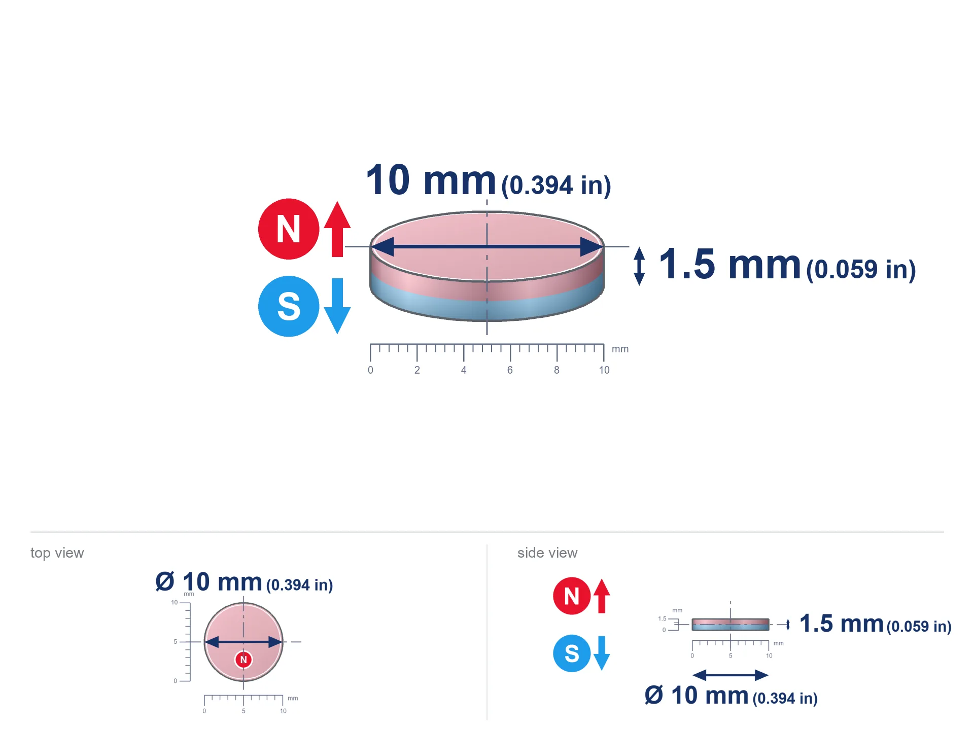
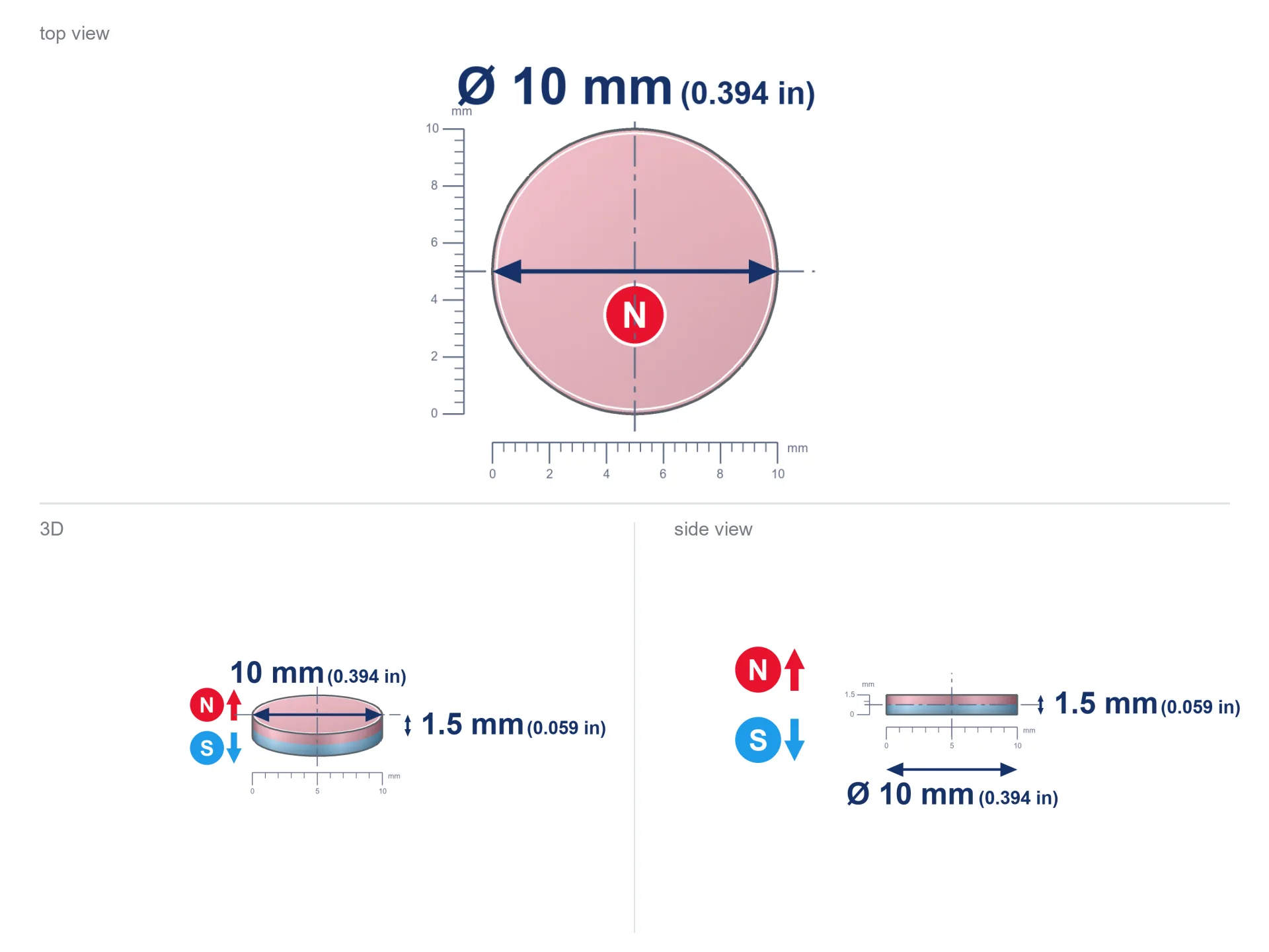
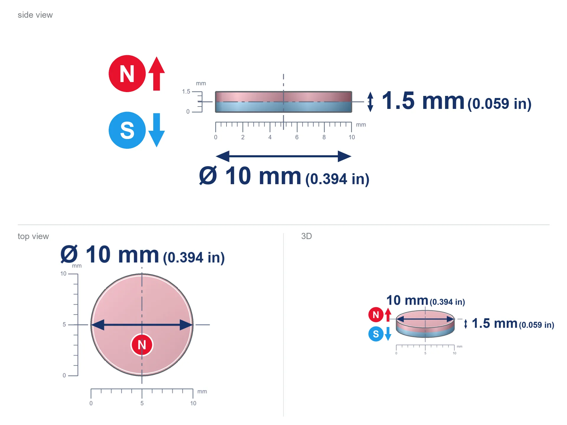
MW 10x1.5 / N52 - cylindrical magnet
cylindrical magnet
Catalog no 010596
GTIN/EAN: 5906301815907
- Diameter Ø
- 10 mm [±0,1 mm]
- Height
- 1.5 mm [±0,1 mm]
- Weight
- 0.88 g
- Magnetization Direction
- ↑ axial
- Coating
- [NiCuNi] Nickel
How we measure these parameters — certificates and measurements
0.550 zł net / pcs
0.677 zł with VAT (23% VAT) / pcs
bulk discounts:
Need more?Frequently asked questions
Where can I buy strong cylindrical neodymium magnets?
Can a small cylindrical magnet provide a strong grip for precise workshop work?
Which cylindrical magnet can work at a higher temperature?
Engineering report for this magnet
Full PDF analysis: pull and shear force, effect of distance, temperature and plate thickness, safety distances and the demagnetization curve.
Call us now
+48 888 99 98 98
alternatively let us know using
contact form
the contact section.
Specifications and structure of a neodymium magnet can be estimated using our
power calculator.
Order by 14:00 and we’ll ship today!
Detailed specification - MW 10x1.5 / N52 - cylindrical magnet
Specification / characteristics - MW 10x1.5 / N52 - cylindrical magnet
| properties | values |
|---|---|
| Cat. no. | 010596 |
| GTIN/EAN | 5906301815907 |
| Distributor | Dhit sp. z o.o. |
| Country of origin | Poland / China / Germany |
| Customs code | 85059029 |
| Diameter Ø | 10 mm [±0,1 mm] |
| Height | 1.5 mm [±0,1 mm] |
| Weight | 0.88 g |
| Magnetization Direction | ↑ axial |
| Load capacity ~ ? | 0.82 kg / 8.04 N |
| Magnetic Induction ~ ? | 207.50 mT / 2075 Gs |
| Coating | [NiCuNi] Nickel |
| Manufacturing Tolerance | ±0.1 mm |
Magnetic properties of material N52
| properties | values | units |
|---|---|---|
| Remanence Br ? | 14.2-14.7 | kGs |
| Remanence Br ? | 1420-1470 | mT |
| Coercivity bHc ? | 10.8-12.5 | kOe |
| Coercivity bHc ? | 860-995 | kA/m |
| Intrinsic coercivity iHc | ≥ 12 | kOe |
| Intrinsic coercivity iHc | ≥ 955 | kA/m |
| Energy product BHmax ? | 48-53 | BH max MGOe |
| Energy product BHmax ? | 380-422 | BH max KJ/m |
| Maximum working temperature ? | ≤ 60 | °C |
Physical properties of sintered neodymium magnets Nd2Fe14B at 20°C
| properties | values | units |
|---|---|---|
| Vickers hardness | ≥550 | Hv |
| Density | ≥7.4 | g/cm3 |
| Curie Temperature TC | 310 | °C |
| Curie Temperature TF | 590 | °F |
| Specific resistance | 150 | μΩ⋅cm |
| Bending strength | 250 | MPa |
| Compressive strength | 1000~1100 | MPa |
| Thermal expansion parallel (∥) to orientation (M) | (3-4) x 10-6 | °C-1 |
| Thermal expansion perpendicular (⊥) to orientation (M) | -(1-3) x 10-6 | °C-1 |
| Young's modulus | 1.7 x 10⁴ | kg/mm² |
Technical analysis of the assembly - data
The following information constitute the outcome of a engineering analysis. Values rely on models for the material Nd2Fe14B. Operational conditions might slightly differ from theoretical values. Use these data as a supplementary guide during assembly planning.
Table 1: Static force (pull vs gap) - characteristics
MW 10x1.5 / N52
| Distance (mm) | Induction (Gauss) / mT | Pull Force (kg/lbs/g/N) | Risk Status |
|---|---|---|---|
| 0 mm |
2074 Gs
207.4 mT
|
0.82 kg / 1.81 pounds
820.0 g / 8.0 N
|
weak grip |
| 1 mm |
1814 Gs
181.4 mT
|
0.63 kg / 1.38 pounds
627.2 g / 6.2 N
|
weak grip |
| 2 mm |
1460 Gs
146.0 mT
|
0.41 kg / 0.90 pounds
406.2 g / 4.0 N
|
weak grip |
| 3 mm |
1116 Gs
111.6 mT
|
0.24 kg / 0.52 pounds
237.4 g / 2.3 N
|
weak grip |
| 5 mm |
618 Gs
61.8 mT
|
0.07 kg / 0.16 pounds
72.8 g / 0.7 N
|
weak grip |
| 10 mm |
164 Gs
16.4 mT
|
0.01 kg / 0.01 pounds
5.1 g / 0.1 N
|
weak grip |
| 15 mm |
60 Gs
6.0 mT
|
0.00 kg / 0.00 pounds
0.7 g / 0.0 N
|
weak grip |
| 20 mm |
28 Gs
2.8 mT
|
0.00 kg / 0.00 pounds
0.1 g / 0.0 N
|
weak grip |
| 30 mm |
9 Gs
0.9 mT
|
0.00 kg / 0.00 pounds
0.0 g / 0.0 N
|
weak grip |
| 50 mm |
2 Gs
0.2 mT
|
0.00 kg / 0.00 pounds
0.0 g / 0.0 N
|
weak grip |
Table 2: Sliding capacity (wall)
MW 10x1.5 / N52
| Distance (mm) | Friction coefficient | Pull Force (kg/lbs/g/N) |
|---|---|---|
| 0 mm | Raw steel (µ ≈ 0.2) |
0.16 kg / 0.36 pounds
164.0 g / 1.6 N
|
| 1 mm | Raw steel (µ ≈ 0.2) |
0.13 kg / 0.28 pounds
126.0 g / 1.2 N
|
| 2 mm | Raw steel (µ ≈ 0.2) |
0.08 kg / 0.18 pounds
82.0 g / 0.8 N
|
| 3 mm | Raw steel (µ ≈ 0.2) |
0.05 kg / 0.11 pounds
48.0 g / 0.5 N
|
| 5 mm | Raw steel (µ ≈ 0.2) |
0.01 kg / 0.03 pounds
14.0 g / 0.1 N
|
| 10 mm | Raw steel (µ ≈ 0.2) |
0.00 kg / 0.00 pounds
2.0 g / 0.0 N
|
| 15 mm | Raw steel (µ ≈ 0.2) |
0.00 kg / 0.00 pounds
0.0 g / 0.0 N
|
| 20 mm | Raw steel (µ ≈ 0.2) |
0.00 kg / 0.00 pounds
0.0 g / 0.0 N
|
| 30 mm | Raw steel (µ ≈ 0.2) |
0.00 kg / 0.00 pounds
0.0 g / 0.0 N
|
| 50 mm | Raw steel (µ ≈ 0.2) |
0.00 kg / 0.00 pounds
0.0 g / 0.0 N
|
Table 3: Vertical assembly (shearing) - vertical pull
MW 10x1.5 / N52
| Surface type | Friction coefficient / % | Max load (kg/lbs/g/N) |
|---|---|---|
| Raw steel |
µ = 0.3
30% of nominal force
|
0.25 kg / 0.54 pounds
246.0 g / 2.4 N
|
| Painted steel (standard) |
µ = 0.2
20% of nominal force
|
0.16 kg / 0.36 pounds
164.0 g / 1.6 N
|
| Oily/slippery steel |
µ = 0.1
10% of nominal force
|
0.08 kg / 0.18 pounds
82.0 g / 0.8 N
|
| Magnet with anti-slip rubber |
µ = 0.5
50% of nominal force
|
0.41 kg / 0.90 pounds
410.0 g / 4.0 N
|
Table 4: Material efficiency (substrate influence) - power losses
MW 10x1.5 / N52
| Steel thickness (mm) | % power | Real pull force (kg/lbs/g/N) |
|---|---|---|
| 0.5 mm |
|
0.08 kg / 0.18 pounds
82.0 g / 0.8 N
|
| 1 mm |
|
0.21 kg / 0.45 pounds
205.0 g / 2.0 N
|
| 2 mm |
|
0.41 kg / 0.90 pounds
410.0 g / 4.0 N
|
| 3 mm |
|
0.62 kg / 1.36 pounds
615.0 g / 6.0 N
|
| 5 mm |
|
0.82 kg / 1.81 pounds
820.0 g / 8.0 N
|
| 10 mm |
|
0.82 kg / 1.81 pounds
820.0 g / 8.0 N
|
| 11 mm |
|
0.82 kg / 1.81 pounds
820.0 g / 8.0 N
|
| 12 mm |
|
0.82 kg / 1.81 pounds
820.0 g / 8.0 N
|
Table 5: Thermal resistance (stability) - power drop
MW 10x1.5 / N52
| Magnet temperature (°C) | Force change relative to 20°C | Remaining pull (kg/lbs/g/N) | Status |
|---|---|---|---|
| 20 °C | 0.0% |
0.82 kg / 1.81 pounds
820.0 g / 8.0 N
|
Estimate |
| 40 °C | -4.4% |
0.78 kg / 1.73 pounds
784.3 g / 7.7 N
|
Estimate |
| 60 °C | -8.6% |
0.75 kg / 1.65 pounds
749.4 g / 7.4 N
|
Material limit |
| 80 °C | — | — | Out of range — no model |
Table 6: Magnet-Magnet interaction (attraction) - forces in the system
MW 10x1.5 / N52
| Gap (mm) | Attraction (kg/lbs) (N-S) | Sliding Force (kg/lbs/g/N) | Repulsion (kg/lbs) (N-N) |
|---|---|---|---|
| 0 mm |
2.08 kg / 4.59 pounds
3 712 Gs
|
0.31 kg / 0.69 pounds
313 g / 3.1 N
|
N/A |
| 1 mm |
1.87 kg / 4.12 pounds
3 929 Gs
|
0.28 kg / 0.62 pounds
280 g / 2.7 N
|
1.68 kg / 3.71 pounds
~0 Gs
|
| 2 mm |
1.59 kg / 3.51 pounds
3 628 Gs
|
0.24 kg / 0.53 pounds
239 g / 2.3 N
|
1.43 kg / 3.16 pounds
~0 Gs
|
| 3 mm |
1.30 kg / 2.88 pounds
3 282 Gs
|
0.20 kg / 0.43 pounds
196 g / 1.9 N
|
1.17 kg / 2.59 pounds
~0 Gs
|
| 5 mm |
0.80 kg / 1.76 pounds
2 565 Gs
|
0.12 kg / 0.26 pounds
119 g / 1.2 N
|
0.72 kg / 1.58 pounds
~0 Gs
|
| 10 mm |
0.18 kg / 0.41 pounds
1 236 Gs
|
0.03 kg / 0.06 pounds
28 g / 0.3 N
|
0.17 kg / 0.37 pounds
~0 Gs
|
| 20 mm |
0.01 kg / 0.03 pounds
327 Gs
|
0.00 kg / 0.00 pounds
2 g / 0.0 N
|
0.01 kg / 0.03 pounds
~0 Gs
|
| 50 mm |
0.00 kg / 0.00 pounds
30 Gs
|
0.00 kg / 0.00 pounds
0 g / 0.0 N
|
0.00 kg / 0.00 pounds
~0 Gs
|
| 60 mm |
0.00 kg / 0.00 pounds
18 Gs
|
0.00 kg / 0.00 pounds
0 g / 0.0 N
|
0.00 kg / 0.00 pounds
~0 Gs
|
| 70 mm |
0.00 kg / 0.00 pounds
12 Gs
|
0.00 kg / 0.00 pounds
0 g / 0.0 N
|
0.00 kg / 0.00 pounds
~0 Gs
|
| 80 mm |
0.00 kg / 0.00 pounds
8 Gs
|
0.00 kg / 0.00 pounds
0 g / 0.0 N
|
0.00 kg / 0.00 pounds
~0 Gs
|
| 90 mm |
0.00 kg / 0.00 pounds
6 Gs
|
0.00 kg / 0.00 pounds
0 g / 0.0 N
|
0.00 kg / 0.00 pounds
~0 Gs
|
| 100 mm |
0.00 kg / 0.00 pounds
4 Gs
|
0.00 kg / 0.00 pounds
0 g / 0.0 N
|
0.00 kg / 0.00 pounds
~0 Gs
|
Table 7: Axial field levels — not safety zones
MW 10x1.5 / N52
| Field level (Gs) | mT | Model distance (cm) |
|---|---|---|
| < 5 Gs | < 0.5 mT | 4.0 cm |
| < 10 Gs | < 1.0 mT | 3.0 cm |
| < 20 Gs | < 2.0 mT | 2.5 cm |
| < 40 Gs | < 4.0 mT | 2.0 cm |
| < 50 Gs | < 5.0 mT | 2.0 cm |
| < 400 Gs | < 40.0 mT | 1.0 cm |
| < 600 Gs | < 60.0 mT | 1.0 cm |
Table 8: Dynamics (cracking risk) - warning
MW 10x1.5 / N52
| Start from (mm) | Speed (km/h) | Energy (J) | Predicted outcome |
|---|---|---|---|
| 10 mm |
23.81 km/h
(6.62 m/s)
|
0.02 J | |
| 30 mm |
23.89 km/h
(6.64 m/s)
|
0.02 J | |
| 50 mm |
23.89 km/h
(6.64 m/s)
|
0.02 J | |
| 100 mm |
23.89 km/h
(6.64 m/s)
|
0.02 J |
Table 9: Corrosion resistance
MW 10x1.5 / N52
| Technical parameter | Value / Description |
|---|---|
| Coating type | [NiCuNi] Nickel |
| Layer structure | Nickel - Copper - Nickel |
| Layer thickness | 10-20 µm |
| Salt spray test (SST) ? | 24 h |
| Recommended environment | Indoors only (dry) |
Table 10: Electrical data (Flux)
MW 10x1.5 / N52
| Parameter | Value | SI Unit / Description |
|---|---|---|
| Magnetic Flux | 2 000 Mx | 20.0 µWb |
| Pc Coefficient | 0.22 | Low (Flat) |
Table 11: Hydrostatics and buoyancy
MW 10x1.5 / N52
| Environment | Effective steel pull | Effect |
|---|---|---|
| Air (land) | 0.82 kg | Standard |
| Water (riverbed) |
0.94 kg
(+0.12 kg buoyancy gain)
|
+14.5% |
1. Vertical hold
*Caution: On a vertical wall, the magnet holds just a fraction of its max power.
2. Plate thickness effect
*Thin metal sheet (e.g. computer case) severely reduces the holding force.
3. Power loss vs temp
N52: the maximum material working temperature is 60°C. Permitted conditions also depend on the shape and magnetic circuit.
4. Demagnetization curve and operating point (B-H)
chart generated for the permeance coefficient Pc (Permeance Coefficient) = 0.22
This simulation demonstrates the magnetic stability of the selected magnet under specific geometric conditions. The solid red line represents the demagnetization curve (material potential), while the dashed blue line is the load line based on the magnet's geometry. The Pc (Permeance Coefficient), also known as the load line slope, is a dimensionless value that describes the relationship between the magnet's shape and its magnetic stability. The intersection of these two lines (the black dot) is the operating point — it determines the actual magnetic flux density generated by the magnet in this specific configuration. A higher Pc value means the magnet is more 'slender' (tall relative to its area), resulting in a higher operating point and better resistance to irreversible demagnetization caused by external fields or temperature. At low Pc values (typical for flat magnets, below about 1) the operating point is closer to the 'knee' of the curve — caution is advised when operating at temperatures near the maximum limit to avoid strength loss.
Chemical composition
| iron (Fe) | 64% – 68% |
| neodymium (Nd) | 29% – 32% |
| boron (B) | 1.1% – 1.2% |
| dysprosium (Dy) | 0.5% – 2.0% |
| coating (Ni-Cu-Ni) | < 0.05% |
Ecology and recycling (GPSR)
| recyclability (EoL) | 100% |
| recycled raw materials | ~10% (pre-cons) |
| carbon footprint | low / zredukowany |
| waste code (EWC) | 16 02 16 |
Other offers

Advantages and disadvantages of neodymium magnets.
Strengths
- Their strength remains stable, and after around 10 years it drops only by ~1% (theoretically),
- They feature excellent resistance to weakening of magnetic properties when exposed to external fields,
- The use of an shiny finish of noble metals (nickel, gold, silver) causes the element to have aesthetics,
- Magnetic induction on the top side of the magnet remains very high,
- Due to their durability and thermal resistance, neodymium magnets are capable of operate (depending on the form) even at high temperatures reaching 230°C or more...
- Thanks to freedom in designing and the ability to modify to complex applications,
- Universal use in electronics industry – they serve a role in data components, electric motors, advanced medical instruments, also multitasking production systems.
- Relatively small size with high pulling force – neodymium magnets offer impressive pulling force in tiny dimensions, which enables their usage in miniature devices
Weaknesses
- They are fragile upon too strong impacts. To avoid cracks, it is worth securing magnets using a steel holder. Such protection not only shields the magnet but also improves its resistance to damage
- Do not exceed this material temperature limit: 60°C. Overheating may permanently weaken the magnet.
- Due to the susceptibility of magnets to corrosion in a humid environment, we advise using waterproof magnets made of rubber, plastic or other material resistant to moisture, in case of application outdoors
- Limited possibility of making nuts in the magnet and complex forms - preferred is a housing - mounting mechanism.
- Possible danger related to microscopic parts of magnets pose a threat, in case of ingestion, which gains importance in the context of child safety. Additionally, small components of these products are able to be problematic in diagnostics medical after entering the body.
- Due to complex production process, their price is higher than average,
Lifting parameters
Optimal lifting capacity of a neodymium magnet – what it depends on?
- on a base made of mild steel, perfectly concentrating the magnetic flux
- with a thickness no less than 10 mm
- characterized by lack of roughness
- with zero gap (without coatings)
- during detachment in a direction perpendicular to the mounting surface
- at temperature room level
Lifting capacity in practice – influencing factors
- Space between surfaces – even a fraction of a millimeter of separation (caused e.g. by varnish or unevenness) drastically reduces the pulling force, often by half at just 0.5 mm.
- Direction of force – maximum parameter is reached only during perpendicular pulling. The resistance to sliding of the magnet along the plate is typically many times smaller (approx. 1/5 of the lifting capacity).
- Plate thickness – too thin sheet does not close the flux, causing part of the power to be escaped to the other side.
- Material composition – different alloys attracts identically. High carbon content worsen the attraction effect.
- Smoothness – ideal contact is possible only on smooth steel. Any scratches and bumps reduce the real contact area, reducing force.
- Thermal environment – heating the magnet results in weakening of force. It is worth remembering the thermal limit for a given model.
Holding force was measured on a smooth steel plate of 20 mm thickness, when the force acted perpendicularly, whereas under attempts to slide the magnet the holding force is lower. Moreover, even a slight gap between the magnet’s surface and the plate decreases the holding force.
Warnings
This is not a toy
Product intended for adults. Tiny parts pose a choking risk, leading to severe trauma. Store away from kids and pets.
Skin irritation risks
Warning for allergy sufferers: The Ni-Cu-Ni coating consists of nickel. If redness occurs, cease handling magnets and use protective gear.
Phone sensors
Navigation devices and mobile phones are extremely sensitive to magnetic fields. Close proximity with a strong magnet can ruin the sensors in your phone.
Flammability
Fire hazard: Rare earth powder is highly flammable. Avoid machining magnets in home conditions as this risks ignition.
Conscious usage
Exercise caution. Rare earth magnets attract from a distance and snap with huge force, often faster than you can react.
Health Danger
Warning for patients: Powerful magnets disrupt electronics. Keep minimum 30 cm distance or ask another person to handle the magnets.
Bone fractures
Danger of trauma: The pulling power is so immense that it can cause blood blisters, crushing, and even bone fractures. Use thick gloves.
Power loss in heat
Do not exceed the maximum operating temperature stated in the specifications of the particular product. The limit depends on the material, geometry and operating arrangement; there is no single threshold for all neodymium magnets. Overheating can permanently weaken a magnet.
Magnet fragility
Neodymium magnets are sintered ceramics, meaning they are prone to chipping. Impact of two magnets leads to them shattering into small pieces.
Data carriers
Powerful magnetic fields can erase data on payment cards, hard drives, and storage devices. Maintain a gap of at least 10 cm.
Tabela kosztu i czasu dostawy
Płatność przed wysyłką:

GLS kurier
Przesyłka będzie u Ciebie za 2-3 dni
14.99 ZŁ

InPost Paczkomaty 24/7
Przesyłka będzie u Ciebie za 1-2 dni
12.30 ZŁ
Płatność przy odbiorze (pobranie):
GLS kurier
Przesyłka będzie u Ciebie za 1-2 dni
23.00 ZŁ