

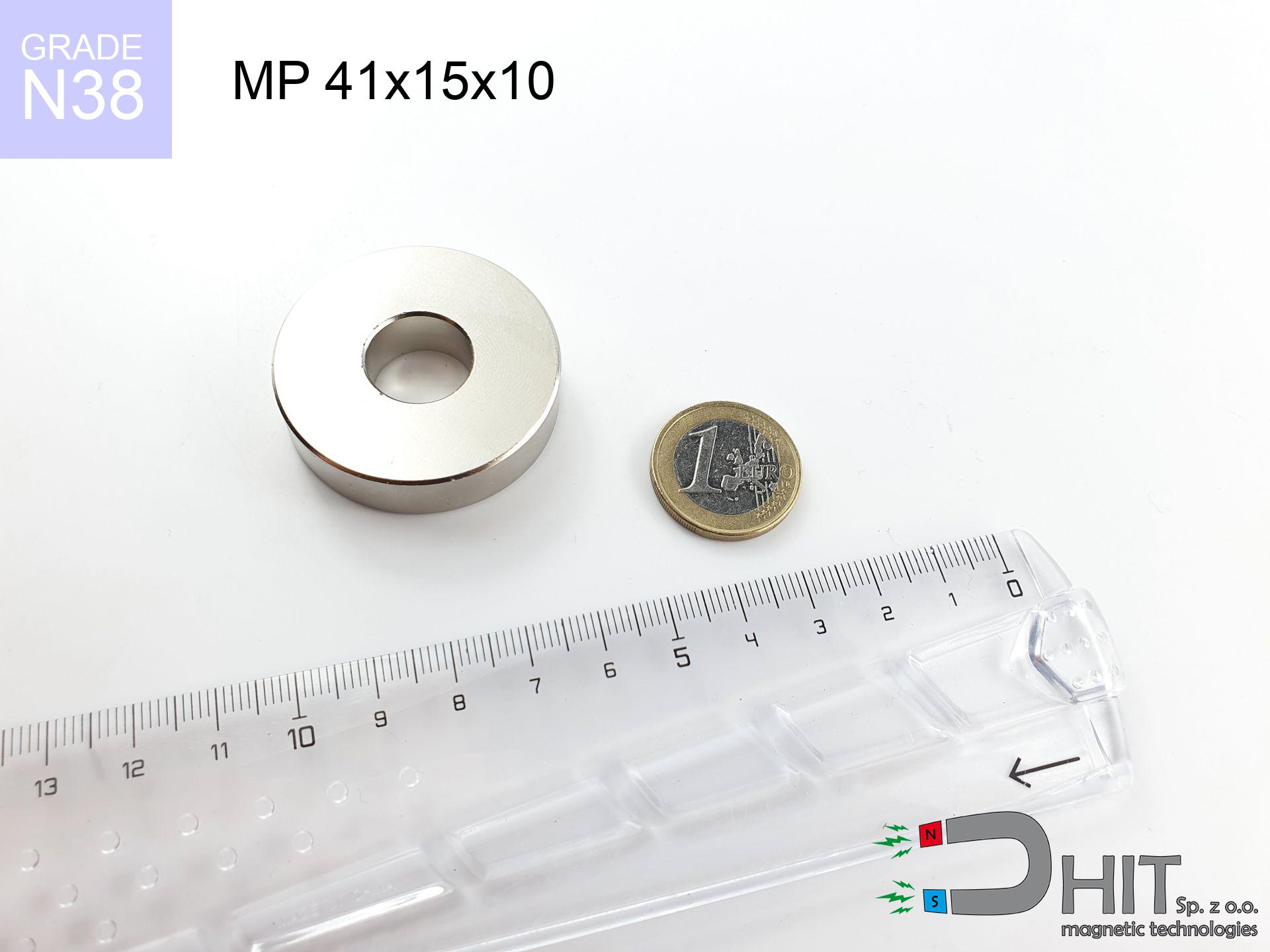
MP 41x15x10 / N38 - ring magnet
ring magnet
Catalog no 030200
GTIN/EAN: 5906301812173
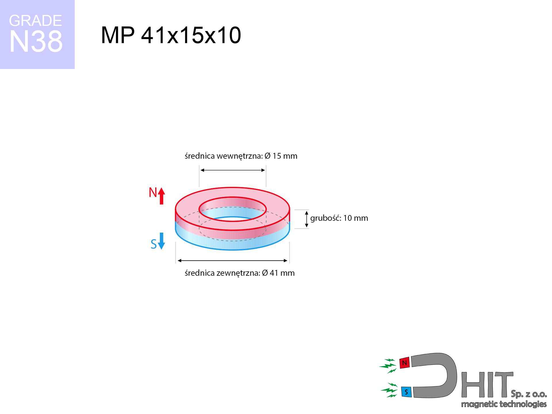
- Diameter
- 41 mm [±0,1 mm]
- internal diameter Ø
- 15 mm [±0,1 mm]
- Height
- 10 mm [±0,1 mm]
- Weight
- 85.77 g
- Magnetization Direction
- ↑ axial
- Coating
- [NiCuNi] Nickel
How we measure these parameters — certificates and measurements
40.65 zł net / pcs
50.00 zł with VAT (23% VAT) / pcs
bulk discounts:
Need more?Frequently asked questions
Where can I compare prices of ring magnets for mounting in Poland?
Are ring magnets resistant to damage?
Which ring magnet is suitable for an outdoor structure?
Where can I check the available sizes of neodymium ring magnets?
Engineering report for this magnet
Full PDF analysis: pull and shear force, effect of distance, temperature and plate thickness, safety distances and the demagnetization curve.
Call us now
+48 888 99 98 98
alternatively let us know using
contact form
the contact section.
Specifications and structure of a neodymium magnet can be estimated using our
power calculator.
Order by 14:00 and we’ll ship today!
Detailed specification - MP 41x15x10 / N38 - ring magnet
Specification / characteristics - MP 41x15x10 / N38 - ring magnet
| properties | values |
|---|---|
| Cat. no. | 030200 |
| GTIN/EAN | 5906301812173 |
| Production/Distribution | Dhit sp. z o.o. |
| Country of origin | Poland / China / Germany |
| Customs code | 85059029 |
| Diameter | 41 mm [±0,1 mm] |
| internal diameter Ø | 15 mm [±0,1 mm] |
| Height | 10 mm [±0,1 mm] |
| Weight | 85.77 g |
| Magnetization Direction | ↑ axial |
| Load capacity ~ ? | 24.44 kg / 239.78 N |
| Magnetic Induction ~ ? | 271.77 mT / 2718 Gs |
| Coating | [NiCuNi] Nickel |
| Manufacturing Tolerance | ±0.1 mm |
Magnetic properties of material N38
| properties | values | units |
|---|---|---|
| Remanence Br ? | 12.2-12.6 | kGs |
| Remanence Br ? | 1220-1260 | mT |
| Coercivity bHc ? | 10.8-11.5 | kOe |
| Coercivity bHc ? | 860-915 | kA/m |
| Intrinsic coercivity iHc | ≥ 12 | kOe |
| Intrinsic coercivity iHc | ≥ 955 | kA/m |
| Energy product BHmax ? | 36-38 | BH max MGOe |
| Energy product BHmax ? | 287-303 | BH max KJ/m |
| Maximum working temperature ? | ≤ 80 | °C |
Physical properties of sintered neodymium magnets Nd2Fe14B at 20°C
| properties | values | units |
|---|---|---|
| Vickers hardness | ≥550 | Hv |
| Density | ≥7.4 | g/cm3 |
| Curie Temperature TC | 310 | °C |
| Curie Temperature TF | 590 | °F |
| Specific resistance | 150 | μΩ⋅cm |
| Bending strength | 250 | MPa |
| Compressive strength | 1000~1100 | MPa |
| Thermal expansion parallel (∥) to orientation (M) | (3-4) x 10-6 | °C-1 |
| Thermal expansion perpendicular (⊥) to orientation (M) | -(1-3) x 10-6 | °C-1 |
| Young's modulus | 1.7 x 10⁴ | kg/mm² |
Technical modeling of the assembly - technical parameters
The following data are the result of a engineering analysis. Values were calculated on algorithms for the material Nd2Fe14B. Operational parameters may differ from theoretical values. Treat these calculations as a preliminary roadmap for designers.
Table 1: Static force (force vs distance) - characteristics
MP 41x15x10 / N38
| Distance (mm) | Induction (Gauss) / mT | Pull Force (kg/lbs/g/N) | Risk Status |
|---|---|---|---|
| 0 mm |
5232 Gs
523.2 mT
|
24.44 kg / 53.88 lbs
24440.0 g / 239.8 N
|
dangerous! |
| 1 mm |
4978 Gs
497.8 mT
|
22.12 kg / 48.77 lbs
22120.4 g / 217.0 N
|
dangerous! |
| 2 mm |
4720 Gs
472.0 mT
|
19.89 kg / 43.85 lbs
19888.8 g / 195.1 N
|
dangerous! |
| 3 mm |
4464 Gs
446.4 mT
|
17.79 kg / 39.22 lbs
17788.4 g / 174.5 N
|
dangerous! |
| 5 mm |
3964 Gs
396.4 mT
|
14.03 kg / 30.93 lbs
14030.8 g / 137.6 N
|
dangerous! |
| 10 mm |
2861 Gs
286.1 mT
|
7.31 kg / 16.11 lbs
7308.1 g / 71.7 N
|
strong |
| 15 mm |
2028 Gs
202.8 mT
|
3.67 kg / 8.09 lbs
3670.1 g / 36.0 N
|
strong |
| 20 mm |
1443 Gs
144.3 mT
|
1.86 kg / 4.10 lbs
1858.4 g / 18.2 N
|
low risk |
| 30 mm |
770 Gs
77.0 mT
|
0.53 kg / 1.17 lbs
529.8 g / 5.2 N
|
low risk |
| 50 mm |
280 Gs
28.0 mT
|
0.07 kg / 0.15 lbs
69.8 g / 0.7 N
|
low risk |
Table 2: Vertical load (wall)
MP 41x15x10 / N38
| Distance (mm) | Friction coefficient | Pull Force (kg/lbs/g/N) |
|---|---|---|
| 0 mm | Stal (~0.2) |
4.89 kg / 10.78 lbs
4888.0 g / 48.0 N
|
| 1 mm | Stal (~0.2) |
4.42 kg / 9.75 lbs
4424.0 g / 43.4 N
|
| 2 mm | Stal (~0.2) |
3.98 kg / 8.77 lbs
3978.0 g / 39.0 N
|
| 3 mm | Stal (~0.2) |
3.56 kg / 7.84 lbs
3558.0 g / 34.9 N
|
| 5 mm | Stal (~0.2) |
2.81 kg / 6.19 lbs
2806.0 g / 27.5 N
|
| 10 mm | Stal (~0.2) |
1.46 kg / 3.22 lbs
1462.0 g / 14.3 N
|
| 15 mm | Stal (~0.2) |
0.73 kg / 1.62 lbs
734.0 g / 7.2 N
|
| 20 mm | Stal (~0.2) |
0.37 kg / 0.82 lbs
372.0 g / 3.6 N
|
| 30 mm | Stal (~0.2) |
0.11 kg / 0.23 lbs
106.0 g / 1.0 N
|
| 50 mm | Stal (~0.2) |
0.01 kg / 0.03 lbs
14.0 g / 0.1 N
|
Table 3: Vertical assembly (sliding) - behavior on slippery surfaces
MP 41x15x10 / N38
| Surface type | Friction coefficient / % Mocy | Max load (kg/lbs/g/N) |
|---|---|---|
| Raw steel |
µ = 0.3
30% Nominalnej Siły
|
7.33 kg / 16.16 lbs
7332.0 g / 71.9 N
|
| Painted steel (standard) |
µ = 0.2
20% Nominalnej Siły
|
4.89 kg / 10.78 lbs
4888.0 g / 48.0 N
|
| Oily/slippery steel |
µ = 0.1
10% Nominalnej Siły
|
2.44 kg / 5.39 lbs
2444.0 g / 24.0 N
|
| Magnet with anti-slip rubber |
µ = 0.5
50% Nominalnej Siły
|
12.22 kg / 26.94 lbs
12220.0 g / 119.9 N
|
Table 4: Material efficiency (substrate influence) - sheet metal selection
MP 41x15x10 / N38
| Steel thickness (mm) | % power | Real pull force (kg/lbs/g/N) |
|---|---|---|
| 0.5 mm |
|
1.22 kg / 2.69 lbs
1222.0 g / 12.0 N
|
| 1 mm |
|
3.06 kg / 6.74 lbs
3055.0 g / 30.0 N
|
| 2 mm |
|
6.11 kg / 13.47 lbs
6110.0 g / 59.9 N
|
| 3 mm |
|
9.17 kg / 20.21 lbs
9165.0 g / 89.9 N
|
| 5 mm |
|
15.28 kg / 33.68 lbs
15275.0 g / 149.8 N
|
| 10 mm |
|
24.44 kg / 53.88 lbs
24440.0 g / 239.8 N
|
| 11 mm |
|
24.44 kg / 53.88 lbs
24440.0 g / 239.8 N
|
| 12 mm |
|
24.44 kg / 53.88 lbs
24440.0 g / 239.8 N
|
Table 5: Thermal stability (stability) - power drop
MP 41x15x10 / N38
| Ambient temp. (°C) | Power loss | Remaining pull (kg/lbs/g/N) | Status |
|---|---|---|---|
| 20 °C | 0.0% |
24.44 kg / 53.88 lbs
24440.0 g / 239.8 N
|
OK |
| 40 °C | -2.2% |
23.90 kg / 52.70 lbs
23902.3 g / 234.5 N
|
OK |
| 60 °C | -4.4% |
23.36 kg / 51.51 lbs
23364.6 g / 229.2 N
|
OK |
| 80 °C | -6.6% |
22.83 kg / 50.32 lbs
22827.0 g / 223.9 N
|
|
| 100 °C | -28.8% |
17.40 kg / 38.36 lbs
17401.3 g / 170.7 N
|
Table 6: Two magnets (attraction) - forces in the system
MP 41x15x10 / N38
| Gap (mm) | Attraction (kg/lbs) (N-S) | Sliding Force (kg/lbs/g/N) | Repulsion (kg/lbs) (N-N) |
|---|---|---|---|
| 0 mm |
178.13 kg / 392.71 lbs
5 907 Gs
|
26.72 kg / 58.91 lbs
26719 g / 262.1 N
|
N/A |
| 1 mm |
169.67 kg / 374.06 lbs
10 213 Gs
|
25.45 kg / 56.11 lbs
25451 g / 249.7 N
|
152.70 kg / 336.65 lbs
~0 Gs
|
| 2 mm |
161.22 kg / 355.43 lbs
9 955 Gs
|
24.18 kg / 53.32 lbs
24183 g / 237.2 N
|
145.10 kg / 319.89 lbs
~0 Gs
|
| 3 mm |
152.98 kg / 337.26 lbs
9 697 Gs
|
22.95 kg / 50.59 lbs
22947 g / 225.1 N
|
137.68 kg / 303.53 lbs
~0 Gs
|
| 5 mm |
137.18 kg / 302.42 lbs
9 183 Gs
|
20.58 kg / 45.36 lbs
20577 g / 201.9 N
|
123.46 kg / 272.18 lbs
~0 Gs
|
| 10 mm |
102.26 kg / 225.45 lbs
7 929 Gs
|
15.34 kg / 33.82 lbs
15339 g / 150.5 N
|
92.04 kg / 202.90 lbs
~0 Gs
|
| 20 mm |
53.26 kg / 117.43 lbs
5 722 Gs
|
7.99 kg / 17.61 lbs
7990 g / 78.4 N
|
47.94 kg / 105.69 lbs
~0 Gs
|
| 50 mm |
7.08 kg / 15.62 lbs
2 087 Gs
|
1.06 kg / 2.34 lbs
1063 g / 10.4 N
|
6.38 kg / 14.06 lbs
~0 Gs
|
| 60 mm |
3.86 kg / 8.51 lbs
1 541 Gs
|
0.58 kg / 1.28 lbs
579 g / 5.7 N
|
3.48 kg / 7.66 lbs
~0 Gs
|
| 70 mm |
2.20 kg / 4.84 lbs
1 162 Gs
|
0.33 kg / 0.73 lbs
330 g / 3.2 N
|
1.98 kg / 4.36 lbs
~0 Gs
|
| 80 mm |
1.30 kg / 2.87 lbs
895 Gs
|
0.20 kg / 0.43 lbs
195 g / 1.9 N
|
1.17 kg / 2.58 lbs
~0 Gs
|
| 90 mm |
0.80 kg / 1.76 lbs
701 Gs
|
0.12 kg / 0.26 lbs
120 g / 1.2 N
|
0.72 kg / 1.59 lbs
~0 Gs
|
| 100 mm |
0.51 kg / 1.12 lbs
559 Gs
|
0.08 kg / 0.17 lbs
76 g / 0.7 N
|
0.46 kg / 1.01 lbs
~0 Gs
|
Table 7: Safety (HSE) (electronics) - warnings
MP 41x15x10 / N38
| Object / Device | Limit (Gauss) / mT | Safe distance |
|---|---|---|
| Pacemaker | 5 Gs (0.5 mT) | 24.0 cm |
| Hearing aid | 10 Gs (1.0 mT) | 19.0 cm |
| Timepiece | 20 Gs (2.0 mT) | 15.0 cm |
| Mobile device | 40 Gs (4.0 mT) | 11.5 cm |
| Remote | 50 Gs (5.0 mT) | 10.5 cm |
| Payment card | 400 Gs (40.0 mT) | 4.5 cm |
| HDD hard drive | 600 Gs (60.0 mT) | 3.5 cm |
Table 8: Impact energy (cracking risk) - warning
MP 41x15x10 / N38
| Start from (mm) | Speed (km/h) | Energy (J) | Predicted outcome |
|---|---|---|---|
| 10 mm |
20.85 km/h
(5.79 m/s)
|
1.44 J | |
| 30 mm |
24.15 km/h
(6.71 m/s)
|
1.93 J | |
| 50 mm |
24.42 km/h
(6.78 m/s)
|
1.97 J | |
| 100 mm |
24.47 km/h
(6.80 m/s)
|
1.98 J |
Table 9: Anti-corrosion coating durability
MP 41x15x10 / N38
| Technical parameter | Value / Description |
|---|---|
| Coating type | [NiCuNi] Nickel |
| Layer structure | Nickel - Copper - Nickel |
| Layer thickness | 10-20 µm |
| Salt spray test (SST) ? | 24 h |
| Recommended environment | Indoors only (dry) |
Table 10: Electrical data (Pc)
MP 41x15x10 / N38
| Parameter | Value | SI Unit / Description |
|---|---|---|
| Magnetic Flux | 56 505 Mx | 565.0 µWb |
| Pc Coefficient | 0.80 | High (Stable) |
Table 11: Physics of underwater searching
MP 41x15x10 / N38
| Environment | Effective steel pull | Effect |
|---|---|---|
| Air (land) | 24.44 kg | Standard |
| Water (riverbed) |
27.98 kg
(+3.54 kg buoyancy gain)
|
+14.5% |
1. Sliding resistance
*Note: On a vertical surface, the magnet holds just a fraction of its perpendicular strength.
2. Steel thickness impact
*Thin steel (e.g. 0.5mm PC case) drastically weakens the holding force.
3. Power loss vs temp
N38: the maximum material working temperature is 80°C. Permitted conditions also depend on the shape and magnetic circuit.
4. Demagnetization curve and operating point (B-H)
chart generated for the permeance coefficient Pc (Permeance Coefficient) = 0.80
This simulation demonstrates the magnetic stability of the selected magnet under specific geometric conditions. The solid red line represents the demagnetization curve (material potential), while the dashed blue line is the load line based on the magnet's geometry. The Pc (Permeance Coefficient), also known as the load line slope, is a dimensionless value that describes the relationship between the magnet's shape and its magnetic stability. The intersection of these two lines (the black dot) is the operating point — it determines the actual magnetic flux density generated by the magnet in this specific configuration. A higher Pc value means the magnet is more 'slender' (tall relative to its area), resulting in a higher operating point and better resistance to irreversible demagnetization caused by external fields or temperature. A value of 0.42 is relatively low (typical for flat magnets), meaning the operating point is closer to the 'knee' of the curve — caution is advised when operating at temperatures near the maximum limit to avoid strength loss.
Chemical composition
| iron (Fe) | 64% – 68% |
| neodymium (Nd) | 29% – 32% |
| boron (B) | 1.1% – 1.2% |
| dysprosium (Dy) | 0.5% – 2.0% |
| coating (Ni-Cu-Ni) | < 0.05% |
Ecology and recycling (GPSR)
| recyclability (EoL) | 100% |
| recycled raw materials | ~10% (pre-cons) |
| carbon footprint | low / zredukowany |
| waste code (EWC) | 16 02 16 |
Other proposals
![SM 25x350 [2xM8] / N42 - magnetic separator](https://cdn3.dhit.pl/graphics/products/sm-25x350-2xm8-pim.jpg "SM 25x350 [2xM8] / N42 - magnetic separator")
![SM 32x325 [2xM8] / N52 - magnetic separator](https://cdn3.dhit.pl/graphics/products/sm-32x325-2xm8-xec.jpg "SM 32x325 [2xM8] / N52 - magnetic separator")

Pros as well as cons of Nd2Fe14B magnets.
Pros
- They virtually do not lose strength, because even after ten years the decline in efficiency is only ~1% (based on calculations),
- They possess excellent resistance to magnetic field loss due to external fields,
- A magnet with a smooth gold surface looks better,
- Magnetic induction on the top side of the magnet turns out to be impressive,
- Thanks to resistance to high temperature, they can operate (depending on the form) even at temperatures up to 230°C and higher...
- Thanks to the ability of flexible molding and customization to custom solutions, NdFeB magnets can be produced in a broad palette of forms and dimensions, which expands the range of possible applications,
- Wide application in modern technologies – they serve a role in magnetic memories, electric motors, advanced medical instruments, also industrial machines.
- Compactness – despite small sizes they provide effective action, making them ideal for precision applications
Disadvantages
- To avoid cracks upon strong impacts, we suggest using special steel housings. Such a solution secures the magnet and simultaneously improves its durability.
- Do not exceed this material temperature limit: 80°C. Overheating may permanently weaken the magnet.
- They oxidize in a humid environment - during use outdoors we suggest using waterproof magnets e.g. in rubber, plastic
- We recommend casing - magnetic mechanism, due to difficulties in producing threads inside the magnet and complicated shapes.
- Health risk resulting from small fragments of magnets can be dangerous, if swallowed, which gains importance in the aspect of protecting the youngest. Additionally, tiny parts of these products can complicate diagnosis medical after entering the body.
- Due to expensive raw materials, their price is relatively high,
Pull force analysis
Maximum lifting capacity of the magnet – what affects it?
- on a block made of structural steel, effectively closing the magnetic field
- possessing a thickness of at least 10 mm to avoid saturation
- with a surface perfectly flat
- under conditions of no distance (surface-to-surface)
- under axial force vector (90-degree angle)
- at ambient temperature room level
What influences lifting capacity in practice
- Space between magnet and steel – every millimeter of distance (caused e.g. by veneer or dirt) diminishes the magnet efficiency, often by half at just 0.5 mm.
- Load vector – highest force is available only during perpendicular pulling. The shear force of the magnet along the surface is usually many times lower (approx. 1/5 of the lifting capacity).
- Substrate thickness – to utilize 100% power, the steel must be sufficiently thick. Paper-thin metal limits the attraction force (the magnet "punches through" it).
- Steel grade – the best choice is high-permeability steel. Hardened steels may generate lower lifting capacity.
- Surface finish – full contact is obtained only on polished steel. Any scratches and bumps create air cushions, reducing force.
- Heat – neodymium magnets have a negative temperature coefficient. When it is hot they lose power, and at low temperatures they can be stronger (up to a certain limit).
Holding force was measured on the plate surface of 20 mm thickness, when the force acted perpendicularly, however under attempts to slide the magnet the holding force is lower. Moreover, even a minimal clearance between the magnet’s surface and the plate lowers the lifting capacity.
Safety rules for work with neodymium magnets
Medical implants
Warning for patients: Powerful magnets affect medical devices. Maintain at least 30 cm distance or request help to work with the magnets.
Product not for children
Strictly keep magnets away from children. Ingestion danger is high, and the consequences of magnets connecting inside the body are very dangerous.
Magnet fragility
Watch out for shards. Magnets can explode upon violent connection, launching sharp fragments into the air. Wear goggles.
Demagnetization risk
Control the heat. Exposing the magnet above 80 degrees Celsius will destroy its properties and pulling force.
Respect the power
Use magnets consciously. Their immense force can surprise even professionals. Stay alert and do not underestimate their force.
Fire risk
Fire warning: Neodymium dust is highly flammable. Avoid machining magnets in home conditions as this may cause fire.
Allergy Warning
Some people suffer from a sensitization to nickel, which is the common plating for NdFeB magnets. Frequent touching might lead to an allergic reaction. It is best to wear protective gloves.
Compass and GPS
A powerful magnetic field negatively affects the functioning of magnetometers in smartphones and navigation systems. Maintain magnets close to a device to avoid breaking the sensors.
Data carriers
Powerful magnetic fields can destroy records on credit cards, HDDs, and storage devices. Stay away of min. 10 cm.
Hand protection
Protect your hands. Two large magnets will join immediately with a force of massive weight, destroying everything in their path. Exercise extreme caution!
Tabela kosztu i czasu dostawy
Płatność przed wysyłką:

GLS kurier
Przesyłka będzie u Ciebie za 2-3 dni
14.99 ZŁ

InPost Paczkomaty 24/7
Przesyłka będzie u Ciebie za 1-2 dni
12.30 ZŁ
Płatność przy odbiorze (pobranie):
GLS kurier
Przesyłka będzie u Ciebie za 1-2 dni
23.00 ZŁ