

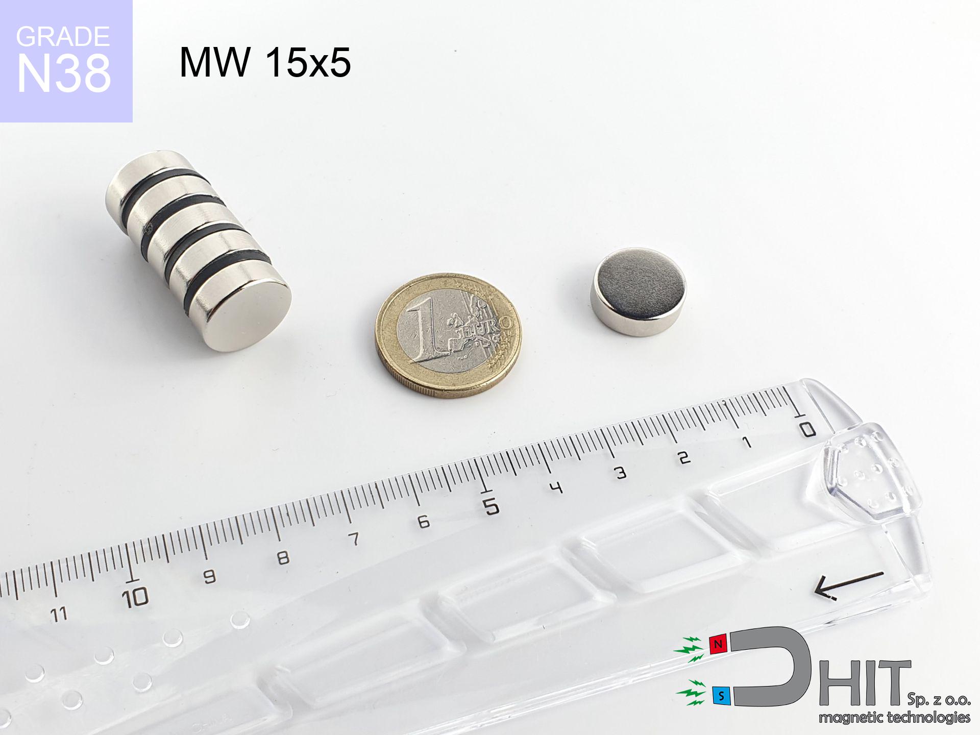
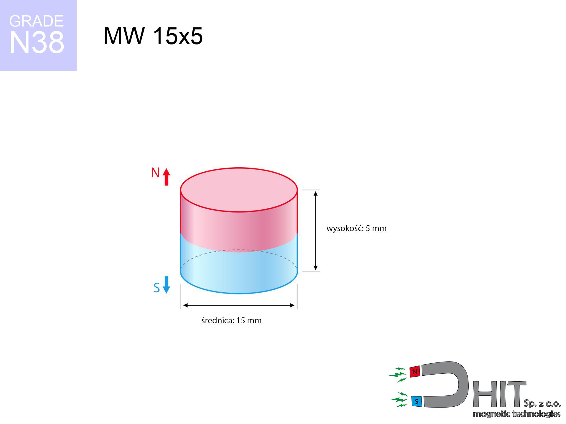
MW 15x5 / N38 - cylindrical magnet
cylindrical magnet
Catalog no 010031
GTIN/EAN: 5906301810308
- Diameter Ø
- 15 mm [±0,1 mm]
- Height
- 5 mm [±0,1 mm]
- Weight
- 6.63 g
- Magnetization Direction
- ↑ axial
- Coating
- [NiCuNi] Nickel
How we measure these parameters — certificates and measurements
2.60 zł net / pcs
3.20 zł with VAT (23% VAT) / pcs
bulk discounts:
Need more?Frequently asked questions
Where can I buy strong cylindrical neodymium magnets?
Can a small cylindrical magnet provide a strong grip for precise workshop work?
Which cylindrical magnet can work at a higher temperature?
Engineering report for this magnet
Full PDF analysis: pull and shear force, effect of distance, temperature and plate thickness, safety distances and the demagnetization curve.
Call us now
+48 888 99 98 98
alternatively let us know using
contact form
the contact section.
Specifications and structure of a neodymium magnet can be estimated using our
power calculator.
Order by 14:00 and we’ll ship today!
Technical specification of the product - MW 15x5 / N38 - cylindrical magnet
Specification / characteristics - MW 15x5 / N38 - cylindrical magnet
| properties | values |
|---|---|
| Cat. no. | 010031 |
| GTIN/EAN | 5906301810308 |
| Production/Distribution | Dhit sp. z o.o. |
| Country of origin | Poland / China / Germany |
| Customs code | 85059029 |
| Diameter Ø | 15 mm [±0,1 mm] |
| Height | 5 mm [±0,1 mm] |
| Weight | 6.63 g |
| Magnetization Direction | ↑ axial |
| Load capacity ~ ? | 5.39 kg / 52.83 N |
| Magnetic Induction ~ ? | 343.70 mT / 3437 Gs |
| Coating | [NiCuNi] Nickel |
| Manufacturing Tolerance | ±0.1 mm |
Magnetic properties of material N38
| properties | values | units |
|---|---|---|
| Remanence Br ? | 12.2-12.6 | kGs |
| Remanence Br ? | 1220-1260 | mT |
| Coercivity bHc ? | 10.8-11.5 | kOe |
| Coercivity bHc ? | 860-915 | kA/m |
| Intrinsic coercivity iHc | ≥ 12 | kOe |
| Intrinsic coercivity iHc | ≥ 955 | kA/m |
| Energy product BHmax ? | 36-38 | BH max MGOe |
| Energy product BHmax ? | 287-303 | BH max KJ/m |
| Maximum working temperature ? | ≤ 80 | °C |
Physical properties of sintered neodymium magnets Nd2Fe14B at 20°C
| properties | values | units |
|---|---|---|
| Vickers hardness | ≥550 | Hv |
| Density | ≥7.4 | g/cm3 |
| Curie Temperature TC | 310 | °C |
| Curie Temperature TF | 590 | °F |
| Specific resistance | 150 | μΩ⋅cm |
| Bending strength | 250 | MPa |
| Compressive strength | 1000~1100 | MPa |
| Thermal expansion parallel (∥) to orientation (M) | (3-4) x 10-6 | °C-1 |
| Thermal expansion perpendicular (⊥) to orientation (M) | -(1-3) x 10-6 | °C-1 |
| Young's modulus | 1.7 x 10⁴ | kg/mm² |
Physical analysis of the assembly - report
These values represent the outcome of a engineering analysis. Values are based on algorithms for the material Nd2Fe14B. Actual conditions may differ. Treat these calculations as a preliminary roadmap during assembly planning.
Table 1: Static pull force (pull vs distance) - power drop
MW 15x5 / N38
| Distance (mm) | Induction (Gauss) / mT | Pull Force (kg/lbs/g/N) | Risk Status |
|---|---|---|---|
| 0 mm |
3436 Gs
343.6 mT
|
5.39 kg / 11.88 lbs
5390.0 g / 52.9 N
|
warning |
| 1 mm |
3054 Gs
305.4 mT
|
4.26 kg / 9.39 lbs
4258.2 g / 41.8 N
|
warning |
| 2 mm |
2633 Gs
263.3 mT
|
3.17 kg / 6.98 lbs
3165.4 g / 31.1 N
|
warning |
| 3 mm |
2221 Gs
222.1 mT
|
2.25 kg / 4.96 lbs
2251.5 g / 22.1 N
|
warning |
| 5 mm |
1521 Gs
152.1 mT
|
1.06 kg / 2.33 lbs
1056.2 g / 10.4 N
|
safe |
| 10 mm |
585 Gs
58.5 mT
|
0.16 kg / 0.35 lbs
156.5 g / 1.5 N
|
safe |
| 15 mm |
260 Gs
26.0 mT
|
0.03 kg / 0.07 lbs
30.8 g / 0.3 N
|
safe |
| 20 mm |
133 Gs
13.3 mT
|
0.01 kg / 0.02 lbs
8.1 g / 0.1 N
|
safe |
| 30 mm |
47 Gs
4.7 mT
|
0.00 kg / 0.00 lbs
1.0 g / 0.0 N
|
safe |
| 50 mm |
12 Gs
1.2 mT
|
0.00 kg / 0.00 lbs
0.1 g / 0.0 N
|
safe |
Table 2: Shear capacity (vertical surface)
MW 15x5 / N38
| Distance (mm) | Friction coefficient | Pull Force (kg/lbs/g/N) |
|---|---|---|
| 0 mm | Stal (~0.2) |
1.08 kg / 2.38 lbs
1078.0 g / 10.6 N
|
| 1 mm | Stal (~0.2) |
0.85 kg / 1.88 lbs
852.0 g / 8.4 N
|
| 2 mm | Stal (~0.2) |
0.63 kg / 1.40 lbs
634.0 g / 6.2 N
|
| 3 mm | Stal (~0.2) |
0.45 kg / 0.99 lbs
450.0 g / 4.4 N
|
| 5 mm | Stal (~0.2) |
0.21 kg / 0.47 lbs
212.0 g / 2.1 N
|
| 10 mm | Stal (~0.2) |
0.03 kg / 0.07 lbs
32.0 g / 0.3 N
|
| 15 mm | Stal (~0.2) |
0.01 kg / 0.01 lbs
6.0 g / 0.1 N
|
| 20 mm | Stal (~0.2) |
0.00 kg / 0.00 lbs
2.0 g / 0.0 N
|
| 30 mm | Stal (~0.2) |
0.00 kg / 0.00 lbs
0.0 g / 0.0 N
|
| 50 mm | Stal (~0.2) |
0.00 kg / 0.00 lbs
0.0 g / 0.0 N
|
Table 3: Wall mounting (sliding) - vertical pull
MW 15x5 / N38
| Surface type | Friction coefficient / % Mocy | Max load (kg/lbs/g/N) |
|---|---|---|
| Raw steel |
µ = 0.3
30% Nominalnej Siły
|
1.62 kg / 3.56 lbs
1617.0 g / 15.9 N
|
| Painted steel (standard) |
µ = 0.2
20% Nominalnej Siły
|
1.08 kg / 2.38 lbs
1078.0 g / 10.6 N
|
| Oily/slippery steel |
µ = 0.1
10% Nominalnej Siły
|
0.54 kg / 1.19 lbs
539.0 g / 5.3 N
|
| Magnet with anti-slip rubber |
µ = 0.5
50% Nominalnej Siły
|
2.70 kg / 5.94 lbs
2695.0 g / 26.4 N
|
Table 4: Material efficiency (substrate influence) - sheet metal selection
MW 15x5 / N38
| Steel thickness (mm) | % power | Real pull force (kg/lbs/g/N) |
|---|---|---|
| 0.5 mm |
|
0.54 kg / 1.19 lbs
539.0 g / 5.3 N
|
| 1 mm |
|
1.35 kg / 2.97 lbs
1347.5 g / 13.2 N
|
| 2 mm |
|
2.70 kg / 5.94 lbs
2695.0 g / 26.4 N
|
| 3 mm |
|
4.04 kg / 8.91 lbs
4042.5 g / 39.7 N
|
| 5 mm |
|
5.39 kg / 11.88 lbs
5390.0 g / 52.9 N
|
| 10 mm |
|
5.39 kg / 11.88 lbs
5390.0 g / 52.9 N
|
| 11 mm |
|
5.39 kg / 11.88 lbs
5390.0 g / 52.9 N
|
| 12 mm |
|
5.39 kg / 11.88 lbs
5390.0 g / 52.9 N
|
Table 5: Thermal resistance (material behavior) - resistance threshold
MW 15x5 / N38
| Ambient temp. (°C) | Power loss | Remaining pull (kg/lbs/g/N) | Status |
|---|---|---|---|
| 20 °C | 0.0% |
5.39 kg / 11.88 lbs
5390.0 g / 52.9 N
|
OK |
| 40 °C | -2.2% |
5.27 kg / 11.62 lbs
5271.4 g / 51.7 N
|
OK |
| 60 °C | -4.4% |
5.15 kg / 11.36 lbs
5152.8 g / 50.5 N
|
|
| 80 °C | -6.6% |
5.03 kg / 11.10 lbs
5034.3 g / 49.4 N
|
|
| 100 °C | -28.8% |
3.84 kg / 8.46 lbs
3837.7 g / 37.6 N
|
Table 6: Two magnets (repulsion) - field collision
MW 15x5 / N38
| Gap (mm) | Attraction (kg/lbs) (N-S) | Shear Force (kg/lbs/g/N) | Repulsion (kg/lbs) (N-N) |
|---|---|---|---|
| 0 mm |
12.86 kg / 28.35 lbs
4 954 Gs
|
1.93 kg / 4.25 lbs
1929 g / 18.9 N
|
N/A |
| 1 mm |
11.54 kg / 25.43 lbs
6 508 Gs
|
1.73 kg / 3.81 lbs
1730 g / 17.0 N
|
10.38 kg / 22.89 lbs
~0 Gs
|
| 2 mm |
10.16 kg / 22.40 lbs
6 107 Gs
|
1.52 kg / 3.36 lbs
1524 g / 14.9 N
|
9.14 kg / 20.16 lbs
~0 Gs
|
| 3 mm |
8.82 kg / 19.44 lbs
5 689 Gs
|
1.32 kg / 2.92 lbs
1322 g / 13.0 N
|
7.93 kg / 17.49 lbs
~0 Gs
|
| 5 mm |
6.40 kg / 14.11 lbs
4 847 Gs
|
0.96 kg / 2.12 lbs
960 g / 9.4 N
|
5.76 kg / 12.70 lbs
~0 Gs
|
| 10 mm |
2.52 kg / 5.56 lbs
3 042 Gs
|
0.38 kg / 0.83 lbs
378 g / 3.7 N
|
2.27 kg / 5.00 lbs
~0 Gs
|
| 20 mm |
0.37 kg / 0.82 lbs
1 171 Gs
|
0.06 kg / 0.12 lbs
56 g / 0.5 N
|
0.34 kg / 0.74 lbs
~0 Gs
|
| 50 mm |
0.01 kg / 0.01 lbs
153 Gs
|
0.00 kg / 0.00 lbs
1 g / 0.0 N
|
0.00 kg / 0.00 lbs
~0 Gs
|
| 60 mm |
0.00 kg / 0.01 lbs
95 Gs
|
0.00 kg / 0.00 lbs
0 g / 0.0 N
|
0.00 kg / 0.00 lbs
~0 Gs
|
| 70 mm |
0.00 kg / 0.00 lbs
63 Gs
|
0.00 kg / 0.00 lbs
0 g / 0.0 N
|
0.00 kg / 0.00 lbs
~0 Gs
|
| 80 mm |
0.00 kg / 0.00 lbs
44 Gs
|
0.00 kg / 0.00 lbs
0 g / 0.0 N
|
0.00 kg / 0.00 lbs
~0 Gs
|
| 90 mm |
0.00 kg / 0.00 lbs
32 Gs
|
0.00 kg / 0.00 lbs
0 g / 0.0 N
|
0.00 kg / 0.00 lbs
~0 Gs
|
| 100 mm |
0.00 kg / 0.00 lbs
23 Gs
|
0.00 kg / 0.00 lbs
0 g / 0.0 N
|
0.00 kg / 0.00 lbs
~0 Gs
|
Table 7: Safety (HSE) (electronics) - precautionary measures
MW 15x5 / N38
| Object / Device | Limit (Gauss) / mT | Safe distance |
|---|---|---|
| Pacemaker | 5 Gs (0.5 mT) | 7.0 cm |
| Hearing aid | 10 Gs (1.0 mT) | 5.5 cm |
| Timepiece | 20 Gs (2.0 mT) | 4.5 cm |
| Phone / Smartphone | 40 Gs (4.0 mT) | 3.5 cm |
| Remote | 50 Gs (5.0 mT) | 3.0 cm |
| Payment card | 400 Gs (40.0 mT) | 1.5 cm |
| HDD hard drive | 600 Gs (60.0 mT) | 1.0 cm |
Table 8: Collisions (kinetic energy) - warning
MW 15x5 / N38
| Start from (mm) | Speed (km/h) | Energy (J) | Predicted outcome |
|---|---|---|---|
| 10 mm |
25.33 km/h
(7.04 m/s)
|
0.16 J | |
| 30 mm |
25.70 km/h
(7.14 m/s)
|
0.17 J | |
| 50 mm |
25.70 km/h
(7.14 m/s)
|
0.17 J | |
| 100 mm |
25.70 km/h
(7.14 m/s)
|
0.17 J |
Table 9: Corrosion resistance
MW 15x5 / N38
| Technical parameter | Value / Description |
|---|---|
| Coating type | [NiCuNi] Nickel |
| Layer structure | Nickel - Copper - Nickel |
| Layer thickness | 10-20 µm |
| Salt spray test (SST) ? | 24 h |
| Recommended environment | Indoors only (dry) |
Table 10: Construction data (Pc)
MW 15x5 / N38
| Parameter | Value | SI Unit / Description |
|---|---|---|
| Magnetic Flux | 6 428 Mx | 64.3 µWb |
| Pc Coefficient | 0.44 | Low (Flat) |
Table 11: Hydrostatics and buoyancy
MW 15x5 / N38
| Environment | Effective steel pull | Effect |
|---|---|---|
| Air (land) | 5.39 kg | Standard |
| Water (riverbed) |
6.17 kg
(+0.78 kg buoyancy gain)
|
+14.5% |
1. Wall mount (shear)
*Caution: On a vertical surface, the magnet holds merely approx. 20-30% of its max power.
2. Plate thickness effect
*Thin steel (e.g. 0.5mm PC case) significantly limits the holding force.
3. Thermal stability
N38: the maximum material working temperature is 80°C. Permitted conditions also depend on the shape and magnetic circuit.
4. Demagnetization curve and operating point (B-H)
chart generated for the permeance coefficient Pc (Permeance Coefficient) = 0.44
The chart above illustrates the magnetic characteristics of the material within the second quadrant of the hysteresis loop. The solid red line represents the demagnetization curve (material potential), while the dashed blue line is the load line based on the magnet's geometry. The Pc (Permeance Coefficient), also known as the load line slope, is a dimensionless value that describes the relationship between the magnet's shape and its magnetic stability. The intersection of these two lines (the black dot) is the operating point — it determines the actual magnetic flux density generated by the magnet in this specific configuration. A higher Pc value means the magnet is more 'slender' (tall relative to its area), resulting in a higher operating point and better resistance to irreversible demagnetization caused by external fields or temperature. A value of 0.42 is relatively low (typical for flat magnets), meaning the operating point is closer to the 'knee' of the curve — caution is advised when operating at temperatures near the maximum limit to avoid strength loss.
Material specification
| iron (Fe) | 64% – 68% |
| neodymium (Nd) | 29% – 32% |
| boron (B) | 1.1% – 1.2% |
| dysprosium (Dy) | 0.5% – 2.0% |
| coating (Ni-Cu-Ni) | < 0.05% |
Sustainability
| recyclability (EoL) | 100% |
| recycled raw materials | ~10% (pre-cons) |
| carbon footprint | low / zredukowany |
| waste code (EWC) | 16 02 16 |
Other products

![MPL 40x10x4x2[7/3.5] / N38 - lamellar magnet](https://cdn3.dhit.pl/graphics/products/mpl40x10x4x27-3.5-suw.jpg "MPL 40x10x4x2[7/3.5] / N38 - lamellar magnet")
![SM 25x275 [2xM8] / N42 - magnetic separator](https://cdn3.dhit.pl/graphics/products/sm-25x275-2xm8-boc.jpg "SM 25x275 [2xM8] / N42 - magnetic separator")
Advantages as well as disadvantages of Nd2Fe14B magnets.
Strengths
- Their strength remains stable, and after approximately ten years it decreases only by ~1% (theoretically),
- Neodymium magnets prove to be highly resistant to loss of magnetic properties caused by external field sources,
- A magnet with a shiny gold surface is more attractive,
- Neodymium magnets achieve maximum magnetic induction on a small area, which allows for strong attraction,
- Neodymium magnets are characterized by very high magnetic induction on the magnet surface and can function (depending on the form) even at a temperature of 230°C or more...
- Thanks to freedom in constructing and the ability to adapt to specific needs,
- Universal use in modern industrial fields – they are used in data components, drive modules, advanced medical instruments, and other advanced devices.
- Relatively small size with high pulling force – neodymium magnets offer impressive pulling force in compact dimensions, which enables their usage in small systems
Cons
- Brittleness is one of their disadvantages. Upon intense impact they can break. We advise keeping them in a strong case, which not only secures them against impacts but also raises their durability
- Do not exceed this material temperature limit: 80°C. Overheating may permanently weaken the magnet.
- They rust in a humid environment. For use outdoors we recommend using waterproof magnets e.g. in rubber, plastic
- We suggest casing - magnetic mechanism, due to difficulties in producing threads inside the magnet and complicated shapes.
- Health risk related to microscopic parts of magnets can be dangerous, in case of ingestion, which is particularly important in the aspect of protecting the youngest. Additionally, tiny parts of these magnets can complicate diagnosis medical when they are in the body.
- Due to complex production process, their price is higher than average,
Pull force analysis
Maximum lifting capacity of the magnet – what it depends on?
- on a base made of structural steel, optimally conducting the magnetic flux
- whose thickness reaches at least 10 mm
- with an ground contact surface
- without any clearance between the magnet and steel
- during pulling in a direction perpendicular to the mounting surface
- at temperature room level
Determinants of practical lifting force of a magnet
- Distance – existence of any layer (paint, tape, gap) acts as an insulator, which lowers power steeply (even by 50% at 0.5 mm).
- Force direction – remember that the magnet has greatest strength perpendicularly. Under sliding down, the capacity drops significantly, often to levels of 20-30% of the nominal value.
- Plate thickness – insufficiently thick sheet does not close the flux, causing part of the power to be wasted into the air.
- Material composition – not every steel reacts the same. High carbon content weaken the attraction effect.
- Smoothness – full contact is obtained only on polished steel. Any scratches and bumps create air cushions, reducing force.
- Temperature influence – hot environment weakens pulling force. Exceeding the limit temperature can permanently damage the magnet.
Lifting capacity was assessed using a polished steel plate of optimal thickness (min. 20 mm), under perpendicular detachment force, however under shearing force the lifting capacity is smaller. In addition, even a minimal clearance between the magnet’s surface and the plate lowers the holding force.
H&S for magnets
Warning for allergy sufferers
Certain individuals experience a hypersensitivity to nickel, which is the standard coating for NdFeB magnets. Extended handling might lead to an allergic reaction. We recommend wear protective gloves.
Do not overheat magnets
Watch the temperature. Heating the magnet to high heat will ruin its properties and strength.
Phone sensors
An intense magnetic field negatively affects the functioning of compasses in smartphones and navigation systems. Maintain magnets close to a device to avoid breaking the sensors.
Keep away from children
Neodymium magnets are not suitable for play. Accidental ingestion of multiple magnets can lead to them connecting inside the digestive tract, which poses a direct threat to life and necessitates urgent medical intervention.
Handling rules
Handle magnets with awareness. Their powerful strength can shock even experienced users. Be vigilant and do not underestimate their force.
Shattering risk
Despite metallic appearance, the material is delicate and not impact-resistant. Avoid impacts, as the magnet may crumble into hazardous fragments.
Data carriers
Device Safety: Neodymium magnets can damage payment cards and sensitive devices (heart implants, hearing aids, timepieces).
Bodily injuries
Protect your hands. Two large magnets will join immediately with a force of massive weight, destroying everything in their path. Exercise extreme caution!
Mechanical processing
Mechanical processing of NdFeB material poses a fire hazard. Magnetic powder reacts violently with oxygen and is difficult to extinguish.
Life threat
Health Alert: Neodymium magnets can deactivate heart devices and defibrillators. Do not approach if you have medical devices.
Tabela kosztu i czasu dostawy
Płatność przed wysyłką:

GLS kurier
Przesyłka będzie u Ciebie za 2-3 dni
14.99 ZŁ

InPost Paczkomaty 24/7
Przesyłka będzie u Ciebie za 1-2 dni
12.30 ZŁ
Płatność przy odbiorze (pobranie):
GLS kurier
Przesyłka będzie u Ciebie za 1-2 dni
23.00 ZŁ