


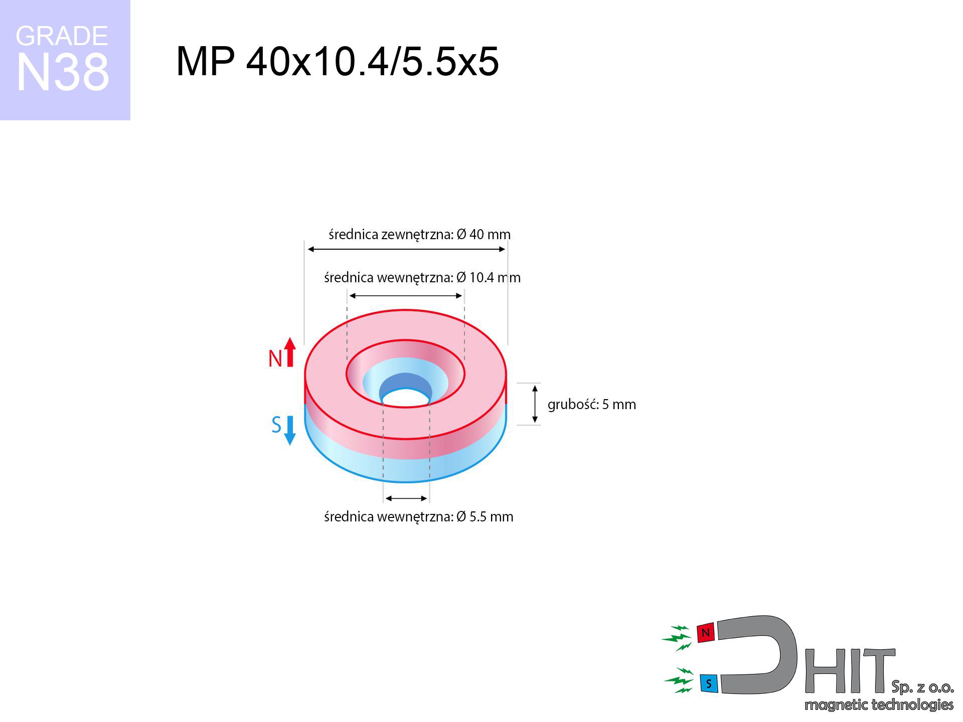
MP 40x10.4/5.5x5 / N38 - ring magnet
ring magnet
Catalog no 030249
GTIN/EAN: 5906301812258
- Diameter
- 40 mm [±0,1 mm]
- internal diameter Ø
- 10.4/5.5 mm [±0,1 mm]
- Height
- 5 mm [±0,1 mm]
- Weight
- 46.23 g
- Magnetization Direction
- ↑ axial
- Coating
- [NiCuNi] Nickel
How we measure these parameters — certificates and measurements
21.95 zł net / pcs
27.00 zł with VAT (23% VAT) / pcs
bulk discounts:
Need more?Frequently asked questions
Where can I compare prices of ring magnets for mounting in Poland?
Are ring magnets resistant to damage?
Which ring magnet is suitable for an outdoor structure?
Where can I check the available sizes of neodymium ring magnets?
Engineering report for this magnet
Full PDF analysis: pull and shear force, effect of distance, temperature and plate thickness, safety distances and the demagnetization curve.
Call us now
+48 888 99 98 98
alternatively let us know using
contact form
the contact section.
Specifications and structure of a neodymium magnet can be estimated using our
power calculator.
Order by 14:00 and we’ll ship today!
Technical data of the product - MP 40x10.4/5.5x5 / N38 - ring magnet
Specification / characteristics - MP 40x10.4/5.5x5 / N38 - ring magnet
| properties | values |
|---|---|
| Cat. no. | 030249 |
| GTIN/EAN | 5906301812258 |
| Production/Distribution | Dhit sp. z o.o. |
| Country of origin | Poland / China / Germany |
| Customs code | 85059029 |
| Diameter | 40 mm [±0,1 mm] |
| internal diameter Ø | 10.4/5.5 mm [±0,1 mm] |
| Height | 5 mm [±0,1 mm] |
| Weight | 46.23 g |
| Magnetization Direction | ↑ axial |
| Load capacity ~ ? | 9.47 kg / 92.86 N |
| Magnetic Induction ~ ? | 150.36 mT / 1504 Gs |
| Coating | [NiCuNi] Nickel |
| Manufacturing Tolerance | ±0.1 mm |
Magnetic properties of material N38
| properties | values | units |
|---|---|---|
| Remanence Br ? | 12.2-12.6 | kGs |
| Remanence Br ? | 1220-1260 | mT |
| Coercivity bHc ? | 10.8-11.5 | kOe |
| Coercivity bHc ? | 860-915 | kA/m |
| Intrinsic coercivity iHc | ≥ 12 | kOe |
| Intrinsic coercivity iHc | ≥ 955 | kA/m |
| Energy product BHmax ? | 36-38 | BH max MGOe |
| Energy product BHmax ? | 287-303 | BH max KJ/m |
| Maximum working temperature ? | ≤ 80 | °C |
Physical properties of sintered neodymium magnets Nd2Fe14B at 20°C
| properties | values | units |
|---|---|---|
| Vickers hardness | ≥550 | Hv |
| Density | ≥7.4 | g/cm3 |
| Curie Temperature TC | 310 | °C |
| Curie Temperature TF | 590 | °F |
| Specific resistance | 150 | μΩ⋅cm |
| Bending strength | 250 | MPa |
| Compressive strength | 1000~1100 | MPa |
| Thermal expansion parallel (∥) to orientation (M) | (3-4) x 10-6 | °C-1 |
| Thermal expansion perpendicular (⊥) to orientation (M) | -(1-3) x 10-6 | °C-1 |
| Young's modulus | 1.7 x 10⁴ | kg/mm² |
Physical simulation of the assembly - report
Presented information constitute the result of a physical analysis. Results are based on models for the material Nd2Fe14B. Actual parameters might slightly differ. Use these data as a supplementary guide when designing systems.
Table 1: Static pull force (pull vs gap) - characteristics
MP 40x10.4/5.5x5 / N38
| Distance (mm) | Induction (Gauss) / mT | Pull Force (kg/lbs/g/N) | Risk Status |
|---|---|---|---|
| 0 mm |
1289 Gs
128.9 mT
|
9.47 kg / 20.88 lbs
9470.0 g / 92.9 N
|
warning |
| 1 mm |
1265 Gs
126.5 mT
|
9.12 kg / 20.11 lbs
9120.9 g / 89.5 N
|
warning |
| 2 mm |
1232 Gs
123.2 mT
|
8.66 kg / 19.10 lbs
8662.7 g / 85.0 N
|
warning |
| 3 mm |
1193 Gs
119.3 mT
|
8.12 kg / 17.90 lbs
8121.3 g / 79.7 N
|
warning |
| 5 mm |
1099 Gs
109.9 mT
|
6.89 kg / 15.18 lbs
6887.8 g / 67.6 N
|
warning |
| 10 mm |
825 Gs
82.5 mT
|
3.88 kg / 8.56 lbs
3882.0 g / 38.1 N
|
warning |
| 15 mm |
580 Gs
58.0 mT
|
1.92 kg / 4.22 lbs
1915.5 g / 18.8 N
|
weak grip |
| 20 mm |
399 Gs
39.9 mT
|
0.91 kg / 2.00 lbs
908.3 g / 8.9 N
|
weak grip |
| 30 mm |
195 Gs
19.5 mT
|
0.22 kg / 0.48 lbs
217.6 g / 2.1 N
|
weak grip |
| 50 mm |
61 Gs
6.1 mT
|
0.02 kg / 0.05 lbs
21.0 g / 0.2 N
|
weak grip |
Table 2: Shear force (wall)
MP 40x10.4/5.5x5 / N38
| Distance (mm) | Friction coefficient | Pull Force (kg/lbs/g/N) |
|---|---|---|
| 0 mm | Raw steel (µ ≈ 0.2) |
1.89 kg / 4.18 lbs
1894.0 g / 18.6 N
|
| 1 mm | Raw steel (µ ≈ 0.2) |
1.82 kg / 4.02 lbs
1824.0 g / 17.9 N
|
| 2 mm | Raw steel (µ ≈ 0.2) |
1.73 kg / 3.82 lbs
1732.0 g / 17.0 N
|
| 3 mm | Raw steel (µ ≈ 0.2) |
1.62 kg / 3.58 lbs
1624.0 g / 15.9 N
|
| 5 mm | Raw steel (µ ≈ 0.2) |
1.38 kg / 3.04 lbs
1378.0 g / 13.5 N
|
| 10 mm | Raw steel (µ ≈ 0.2) |
0.78 kg / 1.71 lbs
776.0 g / 7.6 N
|
| 15 mm | Raw steel (µ ≈ 0.2) |
0.38 kg / 0.85 lbs
384.0 g / 3.8 N
|
| 20 mm | Raw steel (µ ≈ 0.2) |
0.18 kg / 0.40 lbs
182.0 g / 1.8 N
|
| 30 mm | Raw steel (µ ≈ 0.2) |
0.04 kg / 0.10 lbs
44.0 g / 0.4 N
|
| 50 mm | Raw steel (µ ≈ 0.2) |
0.00 kg / 0.01 lbs
4.0 g / 0.0 N
|
Table 3: Wall mounting (shearing) - vertical pull
MP 40x10.4/5.5x5 / N38
| Surface type | Friction coefficient / % | Max load (kg/lbs/g/N) |
|---|---|---|
| Raw steel |
µ = 0.3
30% of nominal force
|
2.84 kg / 6.26 lbs
2841.0 g / 27.9 N
|
| Painted steel (standard) |
µ = 0.2
20% of nominal force
|
1.89 kg / 4.18 lbs
1894.0 g / 18.6 N
|
| Oily/slippery steel |
µ = 0.1
10% of nominal force
|
0.95 kg / 2.09 lbs
947.0 g / 9.3 N
|
| Magnet with anti-slip rubber |
µ = 0.5
50% of nominal force
|
4.74 kg / 10.44 lbs
4735.0 g / 46.5 N
|
Table 4: Steel thickness (substrate influence) - sheet metal selection
MP 40x10.4/5.5x5 / N38
| Steel thickness (mm) | % power | Real pull force (kg/lbs/g/N) |
|---|---|---|
| 0.5 mm |
|
0.95 kg / 2.09 lbs
947.0 g / 9.3 N
|
| 1 mm |
|
2.37 kg / 5.22 lbs
2367.5 g / 23.2 N
|
| 2 mm |
|
4.74 kg / 10.44 lbs
4735.0 g / 46.5 N
|
| 3 mm |
|
7.10 kg / 15.66 lbs
7102.5 g / 69.7 N
|
| 5 mm |
|
9.47 kg / 20.88 lbs
9470.0 g / 92.9 N
|
| 10 mm |
|
9.47 kg / 20.88 lbs
9470.0 g / 92.9 N
|
| 11 mm |
|
9.47 kg / 20.88 lbs
9470.0 g / 92.9 N
|
| 12 mm |
|
9.47 kg / 20.88 lbs
9470.0 g / 92.9 N
|
Table 5: Thermal stability (stability) - thermal limit
MP 40x10.4/5.5x5 / N38
| Magnet temperature (°C) | Force change relative to 20°C | Remaining pull (kg/lbs/g/N) | Status |
|---|---|---|---|
| 20 °C | 0.0% |
9.47 kg / 20.88 lbs
9470.0 g / 92.9 N
|
Estimate |
| 40 °C | -4.4% |
9.06 kg / 19.97 lbs
9057.9 g / 88.9 N
|
Estimate |
| 60 °C | -8.6% |
8.65 kg / 19.08 lbs
8655.0 g / 84.9 N
|
Estimate |
| 80 °C | -12.8% |
8.26 kg / 18.21 lbs
8261.2 g / 81.0 N
|
Material limit |
| 100 °C | — | — | Out of range — no model |
Table 6: Two magnets (attraction) - field collision
MP 40x10.4/5.5x5 / N38
| Gap (mm) | Attraction (kg/lbs) (N-S) | Shear Force (kg/lbs/g/N) | Repulsion (kg/lbs) (N-N) |
|---|---|---|---|
| 0 mm |
10.73 kg / 23.65 lbs
2 424 Gs
|
1.61 kg / 3.55 lbs
1609 g / 15.8 N
|
N/A |
| 1 mm |
10.55 kg / 23.25 lbs
2 555 Gs
|
1.58 kg / 3.49 lbs
1582 g / 15.5 N
|
9.49 kg / 20.93 lbs
~0 Gs
|
| 2 mm |
10.33 kg / 22.78 lbs
2 529 Gs
|
1.55 kg / 3.42 lbs
1550 g / 15.2 N
|
9.30 kg / 20.50 lbs
~0 Gs
|
| 3 mm |
10.09 kg / 22.23 lbs
2 499 Gs
|
1.51 kg / 3.34 lbs
1513 g / 14.8 N
|
9.08 kg / 20.01 lbs
~0 Gs
|
| 5 mm |
9.52 kg / 20.98 lbs
2 427 Gs
|
1.43 kg / 3.15 lbs
1427 g / 14.0 N
|
8.56 kg / 18.88 lbs
~0 Gs
|
| 10 mm |
7.80 kg / 17.20 lbs
2 198 Gs
|
1.17 kg / 2.58 lbs
1170 g / 11.5 N
|
7.02 kg / 15.48 lbs
~0 Gs
|
| 20 mm |
4.40 kg / 9.69 lbs
1 650 Gs
|
0.66 kg / 1.45 lbs
660 g / 6.5 N
|
3.96 kg / 8.72 lbs
~0 Gs
|
| 50 mm |
0.49 kg / 1.09 lbs
553 Gs
|
0.07 kg / 0.16 lbs
74 g / 0.7 N
|
0.44 kg / 0.98 lbs
~0 Gs
|
| 60 mm |
0.25 kg / 0.54 lbs
391 Gs
|
0.04 kg / 0.08 lbs
37 g / 0.4 N
|
0.22 kg / 0.49 lbs
~0 Gs
|
| 70 mm |
0.13 kg / 0.28 lbs
282 Gs
|
0.02 kg / 0.04 lbs
19 g / 0.2 N
|
0.12 kg / 0.26 lbs
~0 Gs
|
| 80 mm |
0.07 kg / 0.15 lbs
209 Gs
|
0.01 kg / 0.02 lbs
11 g / 0.1 N
|
0.06 kg / 0.14 lbs
~0 Gs
|
| 90 mm |
0.04 kg / 0.09 lbs
158 Gs
|
0.01 kg / 0.01 lbs
6 g / 0.1 N
|
0.04 kg / 0.08 lbs
~0 Gs
|
| 100 mm |
0.02 kg / 0.05 lbs
121 Gs
|
0.00 kg / 0.01 lbs
4 g / 0.0 N
|
0.02 kg / 0.05 lbs
~0 Gs
|
Table 7: Axial field levels — not safety zones
MP 40x10.4/5.5x5 / N38
| Field level (Gs) | mT | Model distance (cm) |
|---|---|---|
| < 5 Gs | < 0.5 mT | 12.5 cm |
| < 10 Gs | < 1.0 mT | 10.0 cm |
| < 20 Gs | < 2.0 mT | 8.0 cm |
| < 40 Gs | < 4.0 mT | 6.0 cm |
| < 50 Gs | < 5.0 mT | 5.5 cm |
| < 400 Gs | < 40.0 mT | 2.0 cm |
| < 600 Gs | < 60.0 mT | 1.5 cm |
Table 8: Dynamics (cracking risk) - warning
MP 40x10.4/5.5x5 / N38
| Start from (mm) | Speed (km/h) | Energy (J) | Predicted outcome |
|---|---|---|---|
| 10 mm |
19.38 km/h
(5.38 m/s)
|
0.67 J | |
| 30 mm |
22.72 km/h
(6.31 m/s)
|
0.92 J | |
| 50 mm |
22.91 km/h
(6.36 m/s)
|
0.94 J | |
| 100 mm |
22.94 km/h
(6.37 m/s)
|
0.94 J |
Table 9: Coating parameters (durability)
MP 40x10.4/5.5x5 / N38
| Technical parameter | Value / Description |
|---|---|
| Coating type | [NiCuNi] Nickel |
| Layer structure | Nickel - Copper - Nickel |
| Layer thickness | 10-20 µm |
| Salt spray test (SST) ? | 24 h |
| Recommended environment | Indoors only (dry) |
Table 10: Electrical data (Flux)
MP 40x10.4/5.5x5 / N38
| Parameter | Value | SI Unit / Description |
|---|---|---|
| Magnetic Flux | 17 767 Mx | 177.7 µWb |
| Pc Coefficient | 0.17 | Low (Flat) |
Table 11: Underwater work (magnet fishing)
MP 40x10.4/5.5x5 / N38
| Environment | Effective steel pull | Effect |
|---|---|---|
| Air (land) | 9.47 kg | Standard |
| Water (riverbed) |
10.84 kg
(+1.37 kg buoyancy gain)
|
+14.5% |
1. Vertical hold
*Caution: On a vertical wall, the magnet holds merely approx. 20-30% of its max power.
2. Steel saturation
*Thin metal sheet (e.g. computer case) significantly weakens the holding force.
3. Power loss vs temp
N38: the maximum material working temperature is 80°C. Permitted conditions also depend on the shape and magnetic circuit.
4. Demagnetization curve and operating point (B-H)
chart generated for the permeance coefficient Pc (Permeance Coefficient) = 0.17
This simulation demonstrates the magnetic stability of the selected magnet under specific geometric conditions. The solid red line represents the demagnetization curve (material potential), while the dashed blue line is the load line based on the magnet's geometry. The Pc (Permeance Coefficient), also known as the load line slope, is a dimensionless value that describes the relationship between the magnet's shape and its magnetic stability. The intersection of these two lines (the black dot) is the operating point — it determines the actual magnetic flux density generated by the magnet in this specific configuration. A higher Pc value means the magnet is more 'slender' (tall relative to its area), resulting in a higher operating point and better resistance to irreversible demagnetization caused by external fields or temperature. A value of 0.42 is relatively low (typical for flat magnets), meaning the operating point is closer to the 'knee' of the curve — caution is advised when operating at temperatures near the maximum limit to avoid strength loss.
Material specification
| iron (Fe) | 64% – 68% |
| neodymium (Nd) | 29% – 32% |
| boron (B) | 1.1% – 1.2% |
| dysprosium (Dy) | 0.5% – 2.0% |
| coating (Ni-Cu-Ni) | < 0.05% |
Environmental data
| recyclability (EoL) | 100% |
| recycled raw materials | ~10% (pre-cons) |
| carbon footprint | low / zredukowany |
| waste code (EWC) | 16 02 16 |
See more deals

Advantages as well as disadvantages of neodymium magnets.
Benefits
- Their magnetic field is maintained, and after approximately 10 years it decreases only by ~1% (according to research),
- Magnets very well defend themselves against demagnetization caused by external fields,
- By covering with a smooth coating of silver, the element gains an professional look,
- The surface of neodymium magnets generates a unique magnetic field – this is one of their assets,
- Thanks to resistance to high temperature, they can operate (depending on the form) even at temperatures up to 230°C and higher...
- Possibility of accurate modeling and modifying to complex needs,
- Wide application in electronics industry – they are commonly used in hard drives, electric drive systems, medical devices, also multitasking production systems.
- Relatively small size with high pulling force – neodymium magnets offer impressive pulling force in compact dimensions, which enables their usage in miniature devices
Weaknesses
- At very strong impacts they can break, therefore we advise placing them in special holders. A metal housing provides additional protection against damage, as well as increases the magnet's durability.
- Do not exceed this material temperature limit: 80°C. Overheating may permanently weaken the magnet.
- Magnets exposed to a humid environment can rust. Therefore while using outdoors, we suggest using water-impermeable magnets made of rubber, plastic or other material resistant to moisture
- Due to limitations in creating threads and complex shapes in magnets, we recommend using a housing - magnetic holder.
- Potential hazard to health – tiny shards of magnets are risky, when accidentally swallowed, which becomes key in the context of child safety. It is also worth noting that small elements of these products are able to complicate diagnosis medical after entering the body.
- High unit price – neodymium magnets cost more than other types of magnets (e.g. ferrite), which can limit application in large quantities
Holding force characteristics
Optimal lifting capacity of a neodymium magnet – what contributes to it?
- using a sheet made of mild steel, functioning as a circuit closing element
- whose thickness equals approx. 10 mm
- characterized by smoothness
- without the slightest air gap between the magnet and steel
- during detachment in a direction vertical to the plane
- at ambient temperature approx. 20 degrees Celsius
Determinants of practical lifting force of a magnet
- Distance – the presence of foreign body (rust, tape, gap) interrupts the magnetic circuit, which reduces capacity rapidly (even by 50% at 0.5 mm).
- Direction of force – maximum parameter is obtained only during pulling at a 90° angle. The shear force of the magnet along the plate is typically many times smaller (approx. 1/5 of the lifting capacity).
- Wall thickness – thin material does not allow full use of the magnet. Magnetic flux penetrates through instead of generating force.
- Steel grade – ideal substrate is high-permeability steel. Cast iron may attract less.
- Base smoothness – the smoother and more polished the plate, the better the adhesion and stronger the hold. Roughness creates an air distance.
- Thermal factor – hot environment reduces pulling force. Too high temperature can permanently damage the magnet.
Lifting capacity was assessed with the use of a smooth steel plate of suitable thickness (min. 20 mm), under vertically applied force, in contrast under attempts to slide the magnet the load capacity is reduced by as much as 5 times. Moreover, even a small distance between the magnet and the plate reduces the holding force.
Precautions when working with NdFeB magnets
No play value
These products are not intended for children. Swallowing a few magnets can lead to them connecting inside the digestive tract, which poses a direct threat to life and necessitates immediate surgery.
Impact on smartphones
An intense magnetic field disrupts the functioning of magnetometers in phones and navigation systems. Keep magnets near a smartphone to prevent damaging the sensors.
Dust explosion hazard
Fire hazard: Neodymium dust is explosive. Do not process magnets without safety gear as this risks ignition.
Do not underestimate power
Handle magnets with awareness. Their huge power can shock even experienced users. Plan your moves and respect their power.
Pacemakers
For implant holders: Strong magnetic fields disrupt medical devices. Keep at least 30 cm distance or ask another person to work with the magnets.
Data carriers
Do not bring magnets close to a purse, computer, or TV. The magnetic field can destroy these devices and wipe information from cards.
Permanent damage
Do not exceed the maximum operating temperature stated in the specifications of the particular product. The limit depends on the material, geometry and operating arrangement; there is no single threshold for all neodymium magnets. Overheating can permanently weaken a magnet.
Beware of splinters
Neodymium magnets are sintered ceramics, meaning they are fragile like glass. Collision of two magnets leads to them cracking into small pieces.
Pinching danger
Pinching hazard: The pulling power is so immense that it can cause blood blisters, crushing, and even bone fractures. Use thick gloves.
Warning for allergy sufferers
It is widely known that the nickel plating (standard magnet coating) is a strong allergen. For allergy sufferers, avoid touching magnets with bare hands and opt for encased magnets.
Tabela kosztu i czasu dostawy
Płatność przed wysyłką:

GLS kurier
Przesyłka będzie u Ciebie za 2-3 dni
14.99 ZŁ

InPost Paczkomaty 24/7
Przesyłka będzie u Ciebie za 1-2 dni
12.30 ZŁ
Płatność przy odbiorze (pobranie):
GLS kurier
Przesyłka będzie u Ciebie za 1-2 dni
23.00 ZŁ