

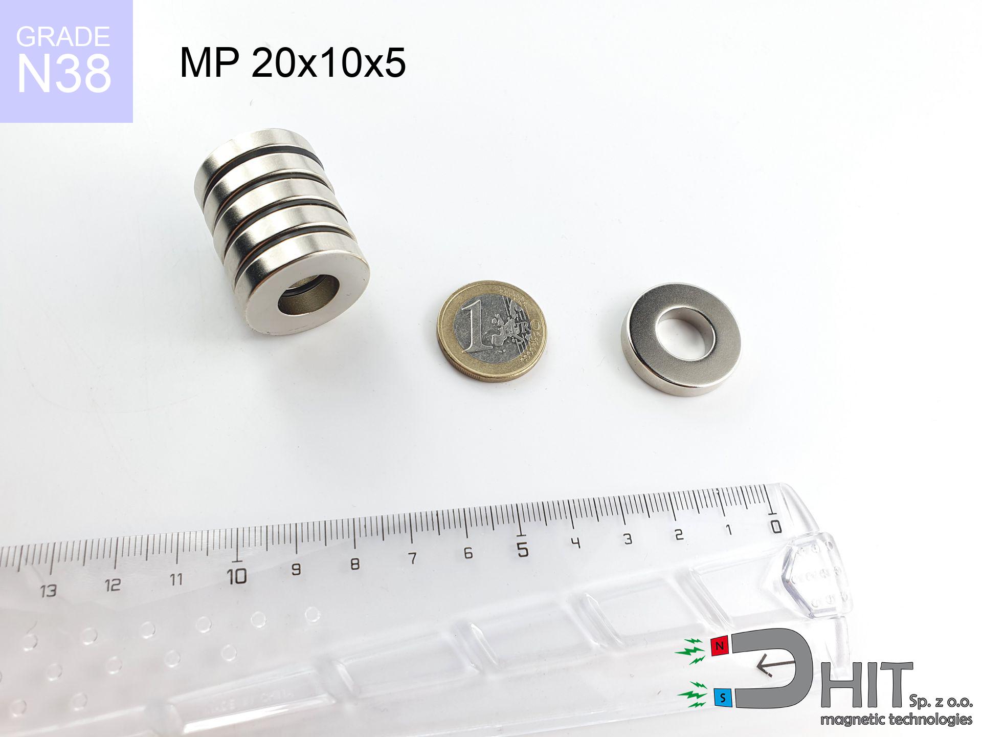
MP 20x10x5 / N38 - ring magnet
ring magnet
Catalog no 030184
GTIN/EAN: 5906301812012
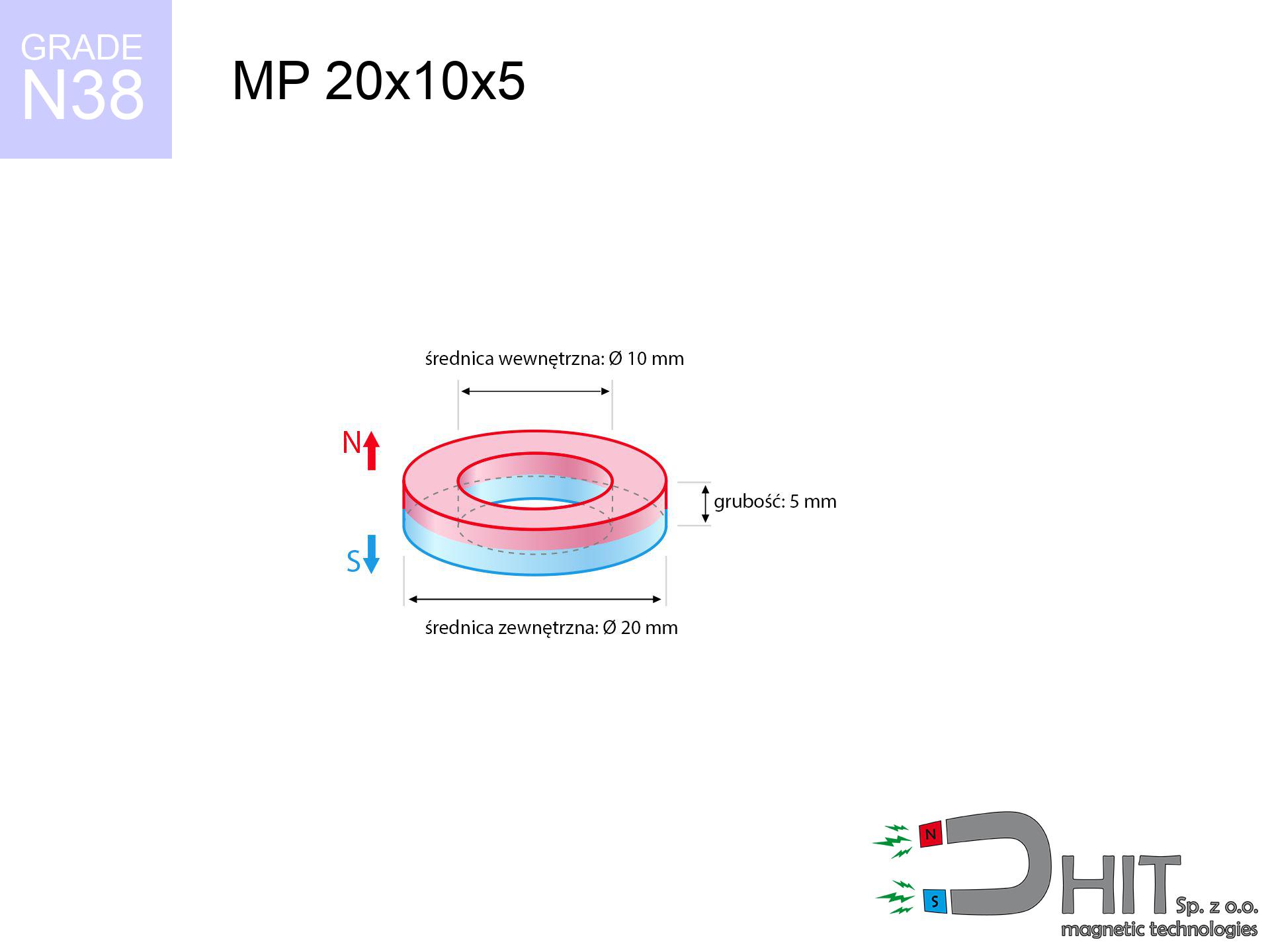
- Diameter
- 20 mm [±0,1 mm]
- internal diameter Ø
- 10 mm [±0,1 mm]
- Height
- 5 mm [±0,1 mm]
- Weight
- 8.84 g
- Magnetization Direction
- ↑ axial
- Coating
- [NiCuNi] Nickel
How we measure these parameters — certificates and measurements
3.66 zł net / pcs
4.50 zł with VAT (23% VAT) / pcs
bulk discounts:
Need more?Frequently asked questions
Where can I compare prices of ring magnets for mounting in Poland?
Are ring magnets resistant to damage?
Which ring magnet is suitable for an outdoor structure?
Where can I check the available sizes of neodymium ring magnets?
Engineering report for this magnet
Full PDF analysis: pull and shear force, effect of distance, temperature and plate thickness, safety distances and the demagnetization curve.
Call us now
+48 888 99 98 98
alternatively let us know using
contact form
the contact section.
Specifications and structure of a neodymium magnet can be estimated using our
power calculator.
Order by 14:00 and we’ll ship today!
Detailed specification - MP 20x10x5 / N38 - ring magnet
Specification / characteristics - MP 20x10x5 / N38 - ring magnet
| properties | values |
|---|---|
| Cat. no. | 030184 |
| GTIN/EAN | 5906301812012 |
| Production/Distribution | Dhit sp. z o.o. |
| Country of origin | Poland / China / Germany |
| Customs code | 85059029 |
| Diameter | 20 mm [±0,1 mm] |
| internal diameter Ø | 10 mm [±0,1 mm] |
| Height | 5 mm [±0,1 mm] |
| Weight | 8.84 g |
| Magnetization Direction | ↑ axial |
| Load capacity ~ ? | 5.20 kg / 50.97 N |
| Magnetic Induction ~ ? | 277.16 mT / 2772 Gs |
| Coating | [NiCuNi] Nickel |
| Manufacturing Tolerance | ±0.1 mm |
Magnetic properties of material N38
| properties | values | units |
|---|---|---|
| Remanence Br ? | 12.2-12.6 | kGs |
| Remanence Br ? | 1220-1260 | mT |
| Coercivity bHc ? | 10.8-11.5 | kOe |
| Coercivity bHc ? | 860-915 | kA/m |
| Intrinsic coercivity iHc | ≥ 12 | kOe |
| Intrinsic coercivity iHc | ≥ 955 | kA/m |
| Energy product BHmax ? | 36-38 | BH max MGOe |
| Energy product BHmax ? | 287-303 | BH max KJ/m |
| Maximum working temperature ? | ≤ 80 | °C |
Physical properties of sintered neodymium magnets Nd2Fe14B at 20°C
| properties | values | units |
|---|---|---|
| Vickers hardness | ≥550 | Hv |
| Density | ≥7.4 | g/cm3 |
| Curie Temperature TC | 310 | °C |
| Curie Temperature TF | 590 | °F |
| Specific resistance | 150 | μΩ⋅cm |
| Bending strength | 250 | MPa |
| Compressive strength | 1000~1100 | MPa |
| Thermal expansion parallel (∥) to orientation (M) | (3-4) x 10-6 | °C-1 |
| Thermal expansion perpendicular (⊥) to orientation (M) | -(1-3) x 10-6 | °C-1 |
| Young's modulus | 1.7 x 10⁴ | kg/mm² |
Engineering analysis of the assembly - report
These values are the result of a physical simulation. Values were calculated on models for the material Nd2Fe14B. Operational conditions might slightly differ from theoretical values. Please consider these data as a reference point when designing systems.
Table 1: Static pull force (pull vs gap) - interaction chart
MP 20x10x5 / N38
| Distance (mm) | Induction (Gauss) / mT | Pull Force (kg/lbs/g/N) | Risk Status |
|---|---|---|---|
| 0 mm |
5917 Gs
591.7 mT
|
5.20 kg / 11.46 lbs
5200.0 g / 51.0 N
|
warning |
| 1 mm |
5321 Gs
532.1 mT
|
4.21 kg / 9.27 lbs
4205.9 g / 41.3 N
|
warning |
| 2 mm |
4736 Gs
473.6 mT
|
3.33 kg / 7.35 lbs
3332.2 g / 32.7 N
|
warning |
| 3 mm |
4184 Gs
418.4 mT
|
2.60 kg / 5.73 lbs
2600.0 g / 25.5 N
|
warning |
| 5 mm |
3216 Gs
321.6 mT
|
1.54 kg / 3.39 lbs
1536.2 g / 15.1 N
|
low risk |
| 10 mm |
1650 Gs
165.0 mT
|
0.40 kg / 0.89 lbs
404.2 g / 4.0 N
|
low risk |
| 15 mm |
907 Gs
90.7 mT
|
0.12 kg / 0.27 lbs
122.3 g / 1.2 N
|
low risk |
| 20 mm |
544 Gs
54.4 mT
|
0.04 kg / 0.10 lbs
44.0 g / 0.4 N
|
low risk |
| 30 mm |
240 Gs
24.0 mT
|
0.01 kg / 0.02 lbs
8.5 g / 0.1 N
|
low risk |
| 50 mm |
75 Gs
7.5 mT
|
0.00 kg / 0.00 lbs
0.8 g / 0.0 N
|
low risk |
Table 2: Slippage load (wall)
MP 20x10x5 / N38
| Distance (mm) | Friction coefficient | Pull Force (kg/lbs/g/N) |
|---|---|---|
| 0 mm | Stal (~0.2) |
1.04 kg / 2.29 lbs
1040.0 g / 10.2 N
|
| 1 mm | Stal (~0.2) |
0.84 kg / 1.86 lbs
842.0 g / 8.3 N
|
| 2 mm | Stal (~0.2) |
0.67 kg / 1.47 lbs
666.0 g / 6.5 N
|
| 3 mm | Stal (~0.2) |
0.52 kg / 1.15 lbs
520.0 g / 5.1 N
|
| 5 mm | Stal (~0.2) |
0.31 kg / 0.68 lbs
308.0 g / 3.0 N
|
| 10 mm | Stal (~0.2) |
0.08 kg / 0.18 lbs
80.0 g / 0.8 N
|
| 15 mm | Stal (~0.2) |
0.02 kg / 0.05 lbs
24.0 g / 0.2 N
|
| 20 mm | Stal (~0.2) |
0.01 kg / 0.02 lbs
8.0 g / 0.1 N
|
| 30 mm | Stal (~0.2) |
0.00 kg / 0.00 lbs
2.0 g / 0.0 N
|
| 50 mm | Stal (~0.2) |
0.00 kg / 0.00 lbs
0.0 g / 0.0 N
|
Table 3: Wall mounting (sliding) - behavior on slippery surfaces
MP 20x10x5 / N38
| Surface type | Friction coefficient / % Mocy | Max load (kg/lbs/g/N) |
|---|---|---|
| Raw steel |
µ = 0.3
30% Nominalnej Siły
|
1.56 kg / 3.44 lbs
1560.0 g / 15.3 N
|
| Painted steel (standard) |
µ = 0.2
20% Nominalnej Siły
|
1.04 kg / 2.29 lbs
1040.0 g / 10.2 N
|
| Oily/slippery steel |
µ = 0.1
10% Nominalnej Siły
|
0.52 kg / 1.15 lbs
520.0 g / 5.1 N
|
| Magnet with anti-slip rubber |
µ = 0.5
50% Nominalnej Siły
|
2.60 kg / 5.73 lbs
2600.0 g / 25.5 N
|
Table 4: Steel thickness (substrate influence) - power losses
MP 20x10x5 / N38
| Steel thickness (mm) | % power | Real pull force (kg/lbs/g/N) |
|---|---|---|
| 0.5 mm |
|
0.52 kg / 1.15 lbs
520.0 g / 5.1 N
|
| 1 mm |
|
1.30 kg / 2.87 lbs
1300.0 g / 12.8 N
|
| 2 mm |
|
2.60 kg / 5.73 lbs
2600.0 g / 25.5 N
|
| 3 mm |
|
3.90 kg / 8.60 lbs
3900.0 g / 38.3 N
|
| 5 mm |
|
5.20 kg / 11.46 lbs
5200.0 g / 51.0 N
|
| 10 mm |
|
5.20 kg / 11.46 lbs
5200.0 g / 51.0 N
|
| 11 mm |
|
5.20 kg / 11.46 lbs
5200.0 g / 51.0 N
|
| 12 mm |
|
5.20 kg / 11.46 lbs
5200.0 g / 51.0 N
|
Table 5: Thermal resistance (stability) - resistance threshold
MP 20x10x5 / N38
| Ambient temp. (°C) | Power loss | Remaining pull (kg/lbs/g/N) | Status |
|---|---|---|---|
| 20 °C | 0.0% |
5.20 kg / 11.46 lbs
5200.0 g / 51.0 N
|
OK |
| 40 °C | -2.2% |
5.09 kg / 11.21 lbs
5085.6 g / 49.9 N
|
OK |
| 60 °C | -4.4% |
4.97 kg / 10.96 lbs
4971.2 g / 48.8 N
|
OK |
| 80 °C | -6.6% |
4.86 kg / 10.71 lbs
4856.8 g / 47.6 N
|
|
| 100 °C | -28.8% |
3.70 kg / 8.16 lbs
3702.4 g / 36.3 N
|
Table 6: Magnet-Magnet interaction (attraction) - forces in the system
MP 20x10x5 / N38
| Gap (mm) | Attraction (kg/lbs) (N-S) | Shear Strength (kg/lbs/g/N) | Repulsion (kg/lbs) (N-N) |
|---|---|---|---|
| 0 mm |
54.03 kg / 119.11 lbs
6 121 Gs
|
8.10 kg / 17.87 lbs
8104 g / 79.5 N
|
N/A |
| 1 mm |
48.76 kg / 107.50 lbs
11 242 Gs
|
7.31 kg / 16.13 lbs
7314 g / 71.8 N
|
43.89 kg / 96.75 lbs
~0 Gs
|
| 2 mm |
43.70 kg / 96.34 lbs
10 642 Gs
|
6.55 kg / 14.45 lbs
6555 g / 64.3 N
|
39.33 kg / 86.71 lbs
~0 Gs
|
| 3 mm |
38.98 kg / 85.94 lbs
10 051 Gs
|
5.85 kg / 12.89 lbs
5847 g / 57.4 N
|
35.08 kg / 77.34 lbs
~0 Gs
|
| 5 mm |
30.63 kg / 67.54 lbs
8 910 Gs
|
4.60 kg / 10.13 lbs
4595 g / 45.1 N
|
27.57 kg / 60.78 lbs
~0 Gs
|
| 10 mm |
15.96 kg / 35.19 lbs
6 432 Gs
|
2.39 kg / 5.28 lbs
2394 g / 23.5 N
|
14.36 kg / 31.67 lbs
~0 Gs
|
| 20 mm |
4.20 kg / 9.26 lbs
3 299 Gs
|
0.63 kg / 1.39 lbs
630 g / 6.2 N
|
3.78 kg / 8.33 lbs
~0 Gs
|
| 50 mm |
0.19 kg / 0.42 lbs
702 Gs
|
0.03 kg / 0.06 lbs
29 g / 0.3 N
|
0.17 kg / 0.38 lbs
~0 Gs
|
| 60 mm |
0.09 kg / 0.20 lbs
480 Gs
|
0.01 kg / 0.03 lbs
13 g / 0.1 N
|
0.08 kg / 0.18 lbs
~0 Gs
|
| 70 mm |
0.05 kg / 0.10 lbs
342 Gs
|
0.01 kg / 0.01 lbs
7 g / 0.1 N
|
0.04 kg / 0.09 lbs
~0 Gs
|
| 80 mm |
0.02 kg / 0.05 lbs
253 Gs
|
0.00 kg / 0.01 lbs
4 g / 0.0 N
|
0.02 kg / 0.05 lbs
~0 Gs
|
| 90 mm |
0.01 kg / 0.03 lbs
193 Gs
|
0.00 kg / 0.00 lbs
2 g / 0.0 N
|
0.01 kg / 0.03 lbs
~0 Gs
|
| 100 mm |
0.01 kg / 0.02 lbs
150 Gs
|
0.00 kg / 0.00 lbs
1 g / 0.0 N
|
0.00 kg / 0.00 lbs
~0 Gs
|
Table 7: Protective zones (electronics) - warnings
MP 20x10x5 / N38
| Object / Device | Limit (Gauss) / mT | Safe distance |
|---|---|---|
| Pacemaker | 5 Gs (0.5 mT) | 14.5 cm |
| Hearing aid | 10 Gs (1.0 mT) | 11.5 cm |
| Timepiece | 20 Gs (2.0 mT) | 9.0 cm |
| Phone / Smartphone | 40 Gs (4.0 mT) | 6.5 cm |
| Car key | 50 Gs (5.0 mT) | 6.0 cm |
| Payment card | 400 Gs (40.0 mT) | 2.5 cm |
| HDD hard drive | 600 Gs (60.0 mT) | 2.0 cm |
Table 8: Collisions (kinetic energy) - warning
MP 20x10x5 / N38
| Start from (mm) | Speed (km/h) | Energy (J) | Predicted outcome |
|---|---|---|---|
| 10 mm |
23.79 km/h
(6.61 m/s)
|
0.19 J | |
| 30 mm |
24.83 km/h
(6.90 m/s)
|
0.21 J | |
| 50 mm |
24.86 km/h
(6.91 m/s)
|
0.21 J | |
| 100 mm |
24.87 km/h
(6.91 m/s)
|
0.21 J |
Table 9: Anti-corrosion coating durability
MP 20x10x5 / N38
| Technical parameter | Value / Description |
|---|---|
| Coating type | [NiCuNi] Nickel |
| Layer structure | Nickel - Copper - Nickel |
| Layer thickness | 10-20 µm |
| Salt spray test (SST) ? | 24 h |
| Recommended environment | Indoors only (dry) |
Table 10: Electrical data (Pc)
MP 20x10x5 / N38
| Parameter | Value | SI Unit / Description |
|---|---|---|
| Magnetic Flux | 16 116 Mx | 161.2 µWb |
| Pc Coefficient | 1.13 | High (Stable) |
Table 11: Physics of underwater searching
MP 20x10x5 / N38
| Environment | Effective steel pull | Effect |
|---|---|---|
| Air (land) | 5.20 kg | Standard |
| Water (riverbed) |
5.95 kg
(+0.75 kg buoyancy gain)
|
+14.5% |
1. Vertical hold
*Note: On a vertical wall, the magnet holds only a fraction of its max power.
2. Efficiency vs thickness
*Thin steel (e.g. 0.5mm PC case) drastically weakens the holding force.
3. Heat tolerance
N38: the maximum material working temperature is 80°C. Permitted conditions also depend on the shape and magnetic circuit.
4. Demagnetization curve and operating point (B-H)
chart generated for the permeance coefficient Pc (Permeance Coefficient) = 1.13
This simulation demonstrates the magnetic stability of the selected magnet under specific geometric conditions. The solid red line represents the demagnetization curve (material potential), while the dashed blue line is the load line based on the magnet's geometry. The Pc (Permeance Coefficient), also known as the load line slope, is a dimensionless value that describes the relationship between the magnet's shape and its magnetic stability. The intersection of these two lines (the black dot) is the operating point — it determines the actual magnetic flux density generated by the magnet in this specific configuration. A higher Pc value means the magnet is more 'slender' (tall relative to its area), resulting in a higher operating point and better resistance to irreversible demagnetization caused by external fields or temperature. A value of 0.42 is relatively low (typical for flat magnets), meaning the operating point is closer to the 'knee' of the curve — caution is advised when operating at temperatures near the maximum limit to avoid strength loss.
Chemical composition
| iron (Fe) | 64% – 68% |
| neodymium (Nd) | 29% – 32% |
| boron (B) | 1.1% – 1.2% |
| dysprosium (Dy) | 0.5% – 2.0% |
| coating (Ni-Cu-Ni) | < 0.05% |
Sustainability
| recyclability (EoL) | 100% |
| recycled raw materials | ~10% (pre-cons) |
| carbon footprint | low / zredukowany |
| waste code (EWC) | 16 02 16 |
See more proposals


Strengths and weaknesses of neodymium magnets.
Benefits
- Their strength is durable, and after around 10 years it drops only by ~1% (theoretically),
- They feature excellent resistance to magnetism drop when exposed to external fields,
- A magnet with a metallic gold surface has better aesthetics,
- The surface of neodymium magnets generates a strong magnetic field – this is a distinguishing feature,
- Neodymium magnets are characterized by extremely high magnetic induction on the magnet surface and can work (depending on the form) even at a temperature of 230°C or more...
- Possibility of accurate modeling and optimizing to atypical needs,
- Wide application in advanced technology sectors – they serve a role in computer drives, electric drive systems, medical devices, and other advanced devices.
- Relatively small size with high pulling force – neodymium magnets offer high power in compact dimensions, which allows their use in miniature devices
Cons
- To avoid cracks under impact, we recommend using special steel holders. Such a solution protects the magnet and simultaneously improves its durability.
- Do not exceed this material temperature limit: 80°C. Overheating may permanently weaken the magnet.
- Due to the susceptibility of magnets to corrosion in a humid environment, we suggest using waterproof magnets made of rubber, plastic or other material resistant to moisture, when using outdoors
- Due to limitations in realizing nuts and complicated forms in magnets, we propose using cover - magnetic mount.
- Health risk to health – tiny shards of magnets pose a threat, if swallowed, which becomes key in the context of child safety. It is also worth noting that small elements of these products can disrupt the diagnostic process medical when they are in the body.
- High unit price – neodymium magnets cost more than other types of magnets (e.g. ferrite), which can limit application in large quantities
Holding force characteristics
Optimal lifting capacity of a neodymium magnet – what affects it?
- with the application of a yoke made of low-carbon steel, ensuring full magnetic saturation
- possessing a thickness of minimum 10 mm to avoid saturation
- with an ideally smooth touching surface
- under conditions of ideal adhesion (surface-to-surface)
- during detachment in a direction vertical to the plane
- at temperature approx. 20 degrees Celsius
Lifting capacity in real conditions – factors
- Space between magnet and steel – every millimeter of separation (caused e.g. by varnish or unevenness) diminishes the magnet efficiency, often by half at just 0.5 mm.
- Force direction – note that the magnet holds strongest perpendicularly. Under shear forces, the holding force drops drastically, often to levels of 20-30% of the maximum value.
- Base massiveness – too thin plate causes magnetic saturation, causing part of the power to be lost into the air.
- Metal type – not every steel reacts the same. High carbon content worsen the interaction with the magnet.
- Surface quality – the more even the plate, the larger the contact zone and stronger the hold. Roughness acts like micro-gaps.
- Temperature – heating the magnet causes a temporary drop of force. It is worth remembering the thermal limit for a given model.
Lifting capacity testing was carried out on a smooth plate of suitable thickness, under perpendicular forces, however under shearing force the lifting capacity is smaller. In addition, even a minimal clearance between the magnet’s surface and the plate decreases the load capacity.
Warnings
Respect the power
Handle magnets consciously. Their powerful strength can shock even experienced users. Be vigilant and do not underestimate their power.
Danger to the youngest
Neodymium magnets are not intended for children. Eating a few magnets can lead to them connecting inside the digestive tract, which poses a direct threat to life and requires immediate surgery.
Maximum temperature
Avoid heat. NdFeB magnets are sensitive to heat. If you require operation above 80°C, look for special high-temperature series (H, SH, UH).
Flammability
Mechanical processing of NdFeB material poses a fire risk. Magnetic powder reacts violently with oxygen and is difficult to extinguish.
Health Danger
Individuals with a pacemaker must keep an absolute distance from magnets. The magnetic field can stop the functioning of the implant.
Electronic hazard
Avoid bringing magnets near a purse, computer, or TV. The magnetism can destroy these devices and erase data from cards.
Keep away from electronics
Be aware: rare earth magnets generate a field that disrupts precision electronics. Keep a separation from your phone, device, and navigation systems.
Skin irritation risks
Allergy Notice: The Ni-Cu-Ni coating contains nickel. If an allergic reaction happens, immediately stop working with magnets and wear gloves.
Protective goggles
Despite the nickel coating, neodymium is delicate and cannot withstand shocks. Avoid impacts, as the magnet may shatter into hazardous fragments.
Physical harm
Mind your fingers. Two large magnets will snap together immediately with a force of several hundred kilograms, destroying everything in their path. Be careful!
Tabela kosztu i czasu dostawy
Płatność przed wysyłką:

GLS kurier
Przesyłka będzie u Ciebie za 2-3 dni
14.99 ZŁ

InPost Paczkomaty 24/7
Przesyłka będzie u Ciebie za 1-2 dni
12.30 ZŁ
Płatność przy odbiorze (pobranie):
GLS kurier
Przesyłka będzie u Ciebie za 1-2 dni
23.00 ZŁ