

MW 9x3 / N38 - cylindrical magnet
cylindrical magnet
Catalog no 010108
GTIN/EAN: 5906301811077
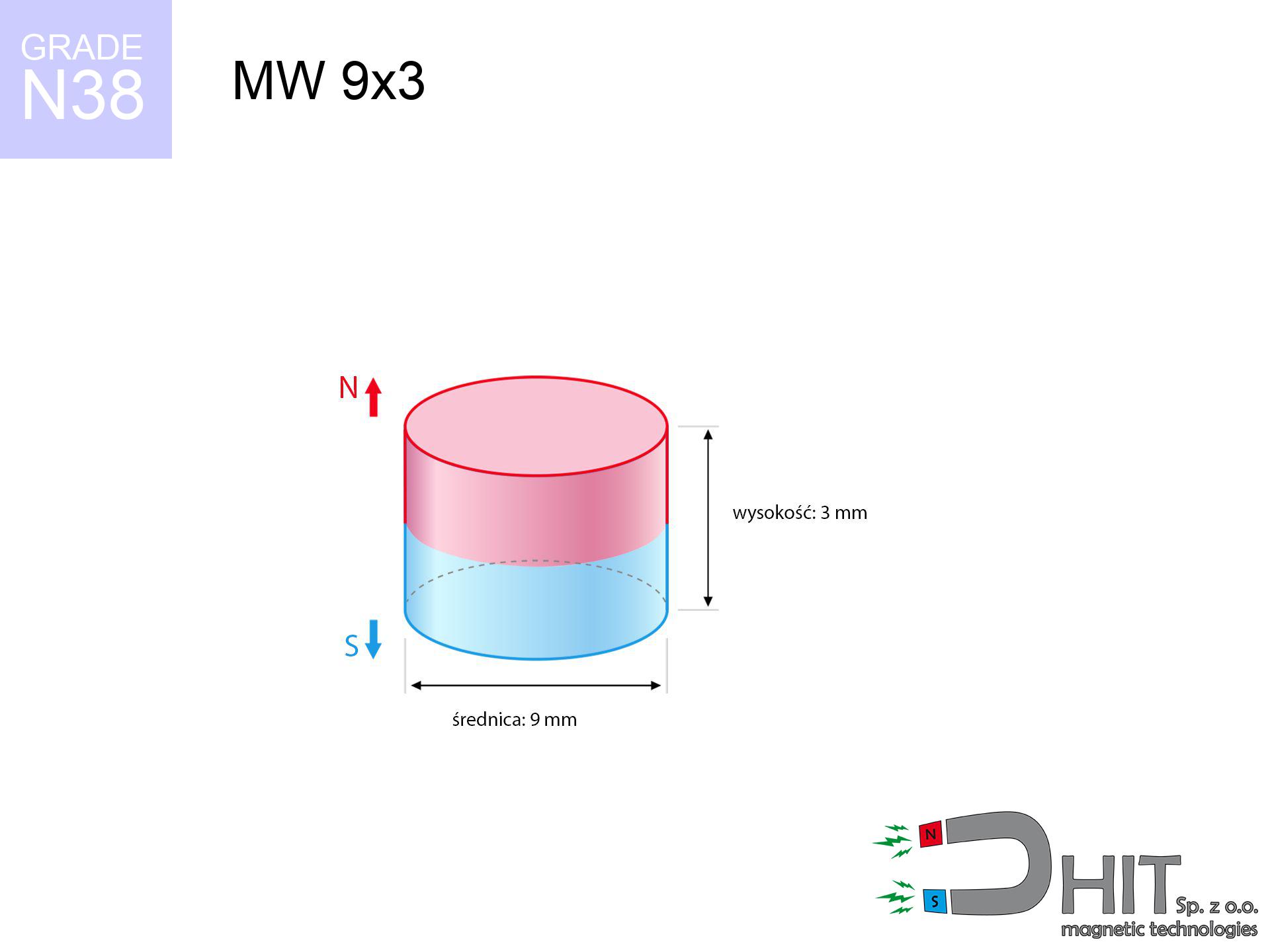
Diameter Ø
9 mm [±0,1 mm]
Height
3 mm [±0,1 mm]
Weight
1.43 g
Magnetization Direction
↑ axial
Load capacity
1.94 kg / 18.99 N
Magnetic Induction
343.55 mT / 3436 Gs
Coating
[NiCuNi] Nickel
1.132 ZŁ with VAT / pcs + price for transport
0.920 ZŁ net + 23% VAT / pcs
bulk discounts:
Need more?
Pick up the phone and ask
+48 888 99 98 98
if you prefer send us a note via
request form
through our site.
Lifting power along with form of magnetic components can be calculated using our
magnetic mass calculator.
Orders submitted before 14:00 will be dispatched today!
Product card - MW 9x3 / N38 - cylindrical magnet
Specification / characteristics - MW 9x3 / N38 - cylindrical magnet
| properties | values |
|---|---|
| Cat. no. | 010108 |
| GTIN/EAN | 5906301811077 |
| Production/Distribution | Dhit sp. z o.o. |
| Country of origin | Poland / China / Germany |
| Customs code | 85059029 |
| Diameter Ø | 9 mm [±0,1 mm] |
| Height | 3 mm [±0,1 mm] |
| Weight | 1.43 g |
| Magnetization Direction | ↑ axial |
| Load capacity ~ ? | 1.94 kg / 18.99 N |
| Magnetic Induction ~ ? | 343.55 mT / 3436 Gs |
| Coating | [NiCuNi] Nickel |
| Manufacturing Tolerance | ±0.1 mm |
Magnetic properties of material N38
| properties | values | units |
|---|---|---|
| remenance Br [min. - max.] ? | 12.2-12.6 | kGs |
| remenance Br [min. - max.] ? | 1220-1260 | mT |
| coercivity bHc ? | 10.8-11.5 | kOe |
| coercivity bHc ? | 860-915 | kA/m |
| actual internal force iHc | ≥ 12 | kOe |
| actual internal force iHc | ≥ 955 | kA/m |
| energy density [min. - max.] ? | 36-38 | BH max MGOe |
| energy density [min. - max.] ? | 287-303 | BH max KJ/m |
| max. temperature ? | ≤ 80 | °C |
Physical properties of sintered neodymium magnets Nd2Fe14B at 20°C
| properties | values | units |
|---|---|---|
| Vickers hardness | ≥550 | Hv |
| Density | ≥7.4 | g/cm3 |
| Curie Temperature TC | 312 - 380 | °C |
| Curie Temperature TF | 593 - 716 | °F |
| Specific resistance | 150 | μΩ⋅cm |
| Bending strength | 250 | MPa |
| Compressive strength | 1000~1100 | MPa |
| Thermal expansion parallel (∥) to orientation (M) | (3-4) x 10-6 | °C-1 |
| Thermal expansion perpendicular (⊥) to orientation (M) | -(1-3) x 10-6 | °C-1 |
| Young's modulus | 1.7 x 10⁴ | kg/mm² |
Engineering modeling of the product - technical parameters
The following data constitute the result of a physical analysis. Results are based on models for the material Nd2Fe14B. Operational parameters might slightly deviate from the simulation results. Treat these data as a reference point during assembly planning.
Table 1: Static pull force (force vs gap) - power drop
MW 9x3 / N38
| Distance (mm) | Induction (Gauss) / mT | Pull Force (kg/lbs/g/N) | Risk Status |
|---|---|---|---|
| 0 mm |
3433 Gs
343.3 mT
|
1.94 kg / 4.28 pounds
1940.0 g / 19.0 N
|
low risk |
| 1 mm |
2774 Gs
277.4 mT
|
1.27 kg / 2.79 pounds
1266.5 g / 12.4 N
|
low risk |
| 2 mm |
2090 Gs
209.0 mT
|
0.72 kg / 1.59 pounds
719.2 g / 7.1 N
|
low risk |
| 3 mm |
1521 Gs
152.1 mT
|
0.38 kg / 0.84 pounds
380.7 g / 3.7 N
|
low risk |
| 5 mm |
795 Gs
79.5 mT
|
0.10 kg / 0.23 pounds
104.1 g / 1.0 N
|
low risk |
| 10 mm |
205 Gs
20.5 mT
|
0.01 kg / 0.02 pounds
6.9 g / 0.1 N
|
low risk |
| 15 mm |
76 Gs
7.6 mT
|
0.00 kg / 0.00 pounds
1.0 g / 0.0 N
|
low risk |
| 20 mm |
36 Gs
3.6 mT
|
0.00 kg / 0.00 pounds
0.2 g / 0.0 N
|
low risk |
| 30 mm |
12 Gs
1.2 mT
|
0.00 kg / 0.00 pounds
0.0 g / 0.0 N
|
low risk |
| 50 mm |
3 Gs
0.3 mT
|
0.00 kg / 0.00 pounds
0.0 g / 0.0 N
|
low risk |
Table 2: Shear capacity (wall)
MW 9x3 / N38
| Distance (mm) | Friction coefficient | Pull Force (kg/lbs/g/N) |
|---|---|---|
| 0 mm | Stal (~0.2) |
0.39 kg / 0.86 pounds
388.0 g / 3.8 N
|
| 1 mm | Stal (~0.2) |
0.25 kg / 0.56 pounds
254.0 g / 2.5 N
|
| 2 mm | Stal (~0.2) |
0.14 kg / 0.32 pounds
144.0 g / 1.4 N
|
| 3 mm | Stal (~0.2) |
0.08 kg / 0.17 pounds
76.0 g / 0.7 N
|
| 5 mm | Stal (~0.2) |
0.02 kg / 0.04 pounds
20.0 g / 0.2 N
|
| 10 mm | Stal (~0.2) |
0.00 kg / 0.00 pounds
2.0 g / 0.0 N
|
| 15 mm | Stal (~0.2) |
0.00 kg / 0.00 pounds
0.0 g / 0.0 N
|
| 20 mm | Stal (~0.2) |
0.00 kg / 0.00 pounds
0.0 g / 0.0 N
|
| 30 mm | Stal (~0.2) |
0.00 kg / 0.00 pounds
0.0 g / 0.0 N
|
| 50 mm | Stal (~0.2) |
0.00 kg / 0.00 pounds
0.0 g / 0.0 N
|
Table 3: Wall mounting (sliding) - vertical pull
MW 9x3 / N38
| Surface type | Friction coefficient / % Mocy | Max load (kg/lbs/g/N) |
|---|---|---|
| Raw steel |
µ = 0.3
30% Nominalnej Siły
|
0.58 kg / 1.28 pounds
582.0 g / 5.7 N
|
| Painted steel (standard) |
µ = 0.2
20% Nominalnej Siły
|
0.39 kg / 0.86 pounds
388.0 g / 3.8 N
|
| Oily/slippery steel |
µ = 0.1
10% Nominalnej Siły
|
0.19 kg / 0.43 pounds
194.0 g / 1.9 N
|
| Magnet with anti-slip rubber |
µ = 0.5
50% Nominalnej Siły
|
0.97 kg / 2.14 pounds
970.0 g / 9.5 N
|
Table 4: Material efficiency (saturation) - sheet metal selection
MW 9x3 / N38
| Steel thickness (mm) | % power | Real pull force (kg/lbs/g/N) |
|---|---|---|
| 0.5 mm |
|
0.19 kg / 0.43 pounds
194.0 g / 1.9 N
|
| 1 mm |
|
0.49 kg / 1.07 pounds
485.0 g / 4.8 N
|
| 2 mm |
|
0.97 kg / 2.14 pounds
970.0 g / 9.5 N
|
| 3 mm |
|
1.46 kg / 3.21 pounds
1455.0 g / 14.3 N
|
| 5 mm |
|
1.94 kg / 4.28 pounds
1940.0 g / 19.0 N
|
| 10 mm |
|
1.94 kg / 4.28 pounds
1940.0 g / 19.0 N
|
| 11 mm |
|
1.94 kg / 4.28 pounds
1940.0 g / 19.0 N
|
| 12 mm |
|
1.94 kg / 4.28 pounds
1940.0 g / 19.0 N
|
Table 5: Thermal resistance (material behavior) - power drop
MW 9x3 / N38
| Ambient temp. (°C) | Power loss | Remaining pull (kg/lbs/g/N) | Status |
|---|---|---|---|
| 20 °C | 0.0% |
1.94 kg / 4.28 pounds
1940.0 g / 19.0 N
|
OK |
| 40 °C | -2.2% |
1.90 kg / 4.18 pounds
1897.3 g / 18.6 N
|
OK |
| 60 °C | -4.4% |
1.85 kg / 4.09 pounds
1854.6 g / 18.2 N
|
|
| 80 °C | -6.6% |
1.81 kg / 3.99 pounds
1812.0 g / 17.8 N
|
|
| 100 °C | -28.8% |
1.38 kg / 3.05 pounds
1381.3 g / 13.6 N
|
Table 6: Magnet-Magnet interaction (repulsion) - field range
MW 9x3 / N38
| Gap (mm) | Attraction (kg/lbs) (N-S) | Lateral Force (kg/lbs/g/N) | Repulsion (kg/lbs) (N-N) |
|---|---|---|---|
| 0 mm |
4.62 kg / 10.19 pounds
4 949 Gs
|
0.69 kg / 1.53 pounds
693 g / 6.8 N
|
N/A |
| 1 mm |
3.82 kg / 8.43 pounds
6 244 Gs
|
0.57 kg / 1.26 pounds
573 g / 5.6 N
|
3.44 kg / 7.58 pounds
~0 Gs
|
| 2 mm |
3.02 kg / 6.65 pounds
5 548 Gs
|
0.45 kg / 1.00 pounds
453 g / 4.4 N
|
2.72 kg / 5.99 pounds
~0 Gs
|
| 3 mm |
2.30 kg / 5.08 pounds
4 847 Gs
|
0.35 kg / 0.76 pounds
346 g / 3.4 N
|
2.07 kg / 4.57 pounds
~0 Gs
|
| 5 mm |
1.25 kg / 2.76 pounds
3 575 Gs
|
0.19 kg / 0.41 pounds
188 g / 1.8 N
|
1.13 kg / 2.49 pounds
~0 Gs
|
| 10 mm |
0.25 kg / 0.55 pounds
1 591 Gs
|
0.04 kg / 0.08 pounds
37 g / 0.4 N
|
0.22 kg / 0.49 pounds
~0 Gs
|
| 20 mm |
0.02 kg / 0.04 pounds
410 Gs
|
0.00 kg / 0.01 pounds
2 g / 0.0 N
|
0.01 kg / 0.03 pounds
~0 Gs
|
| 50 mm |
0.00 kg / 0.00 pounds
39 Gs
|
0.00 kg / 0.00 pounds
0 g / 0.0 N
|
0.00 kg / 0.00 pounds
~0 Gs
|
| 60 mm |
0.00 kg / 0.00 pounds
23 Gs
|
0.00 kg / 0.00 pounds
0 g / 0.0 N
|
0.00 kg / 0.00 pounds
~0 Gs
|
| 70 mm |
0.00 kg / 0.00 pounds
15 Gs
|
0.00 kg / 0.00 pounds
0 g / 0.0 N
|
0.00 kg / 0.00 pounds
~0 Gs
|
| 80 mm |
0.00 kg / 0.00 pounds
10 Gs
|
0.00 kg / 0.00 pounds
0 g / 0.0 N
|
0.00 kg / 0.00 pounds
~0 Gs
|
| 90 mm |
0.00 kg / 0.00 pounds
7 Gs
|
0.00 kg / 0.00 pounds
0 g / 0.0 N
|
0.00 kg / 0.00 pounds
~0 Gs
|
| 100 mm |
0.00 kg / 0.00 pounds
5 Gs
|
0.00 kg / 0.00 pounds
0 g / 0.0 N
|
0.00 kg / 0.00 pounds
~0 Gs
|
Table 7: Hazards (implants) - warnings
MW 9x3 / N38
| Object / Device | Limit (Gauss) / mT | Safe distance |
|---|---|---|
| Pacemaker | 5 Gs (0.5 mT) | 4.5 cm |
| Hearing aid | 10 Gs (1.0 mT) | 3.5 cm |
| Timepiece | 20 Gs (2.0 mT) | 2.5 cm |
| Phone / Smartphone | 40 Gs (4.0 mT) | 2.0 cm |
| Remote | 50 Gs (5.0 mT) | 2.0 cm |
| Payment card | 400 Gs (40.0 mT) | 1.0 cm |
| HDD hard drive | 600 Gs (60.0 mT) | 1.0 cm |
Table 8: Dynamics (cracking risk) - collision effects
MW 9x3 / N38
| Start from (mm) | Speed (km/h) | Energy (J) | Predicted outcome |
|---|---|---|---|
| 10 mm |
37.23 km/h
(10.34 m/s)
|
0.08 J | |
| 30 mm |
64.34 km/h
(17.87 m/s)
|
0.23 J | |
| 50 mm |
83.06 km/h
(23.07 m/s)
|
0.38 J | |
| 100 mm |
117.47 km/h
(32.63 m/s)
|
0.76 J |
Table 9: Corrosion resistance
MW 9x3 / N38
| Technical parameter | Value / Description |
|---|---|
| Coating type | [NiCuNi] Nickel |
| Layer structure | Nickel - Copper - Nickel |
| Layer thickness | 10-20 µm |
| Salt spray test (SST) ? | 24 h |
| Recommended environment | Indoors only (dry) |
Table 10: Electrical data (Pc)
MW 9x3 / N38
| Parameter | Value | SI Unit / Description |
|---|---|---|
| Magnetic Flux | 2 314 Mx | 23.1 µWb |
| Pc Coefficient | 0.44 | Low (Flat) |
Table 11: Submerged application
MW 9x3 / N38
| Environment | Effective steel pull | Effect |
|---|---|---|
| Air (land) | 1.94 kg | Standard |
| Water (riverbed) |
2.22 kg
(+0.28 kg buoyancy gain)
|
+14.5% |
1. Wall mount (shear)
*Caution: On a vertical wall, the magnet holds just approx. 20-30% of its nominal pull.
2. Steel thickness impact
*Thin metal sheet (e.g. 0.5mm PC case) drastically limits the holding force.
3. Thermal stability
*For standard magnets, the safety limit is 80°C.
4. Demagnetization curve and operating point (B-H)
chart generated for the permeance coefficient Pc (Permeance Coefficient) = 0.44
The chart above illustrates the magnetic characteristics of the material within the second quadrant of the hysteresis loop. The solid red line represents the demagnetization curve (material potential), while the dashed blue line is the load line based on the magnet's geometry. The Pc (Permeance Coefficient), also known as the load line slope, is a dimensionless value that describes the relationship between the magnet's shape and its magnetic stability. The intersection of these two lines (the black dot) is the operating point — it determines the actual magnetic flux density generated by the magnet in this specific configuration. A higher Pc value means the magnet is more 'slender' (tall relative to its area), resulting in a higher operating point and better resistance to irreversible demagnetization caused by external fields or temperature. A value of 0.42 is relatively low (typical for flat magnets), meaning the operating point is closer to the 'knee' of the curve — caution is advised when operating at temperatures near the maximum limit to avoid strength loss.
Material specification
| iron (Fe) | 64% – 68% |
| neodymium (Nd) | 29% – 32% |
| boron (B) | 1.1% – 1.2% |
| dysprosium (Dy) | 0.5% – 2.0% |
| coating (Ni-Cu-Ni) | < 0.05% |
Environmental data
| recyclability (EoL) | 100% |
| recycled raw materials | ~10% (pre-cons) |
| carbon footprint | low / zredukowany |
| waste code (EWC) | 16 02 16 |
Other deals

![AM ucho małe [M8] - magnetic accessories](https://cdn3.dhit.pl/graphics/products/am-ucho-małe-m8-zud.jpg "AM ucho małe [M8] - magnetic accessories")


Strengths as well as weaknesses of Nd2Fe14B magnets.
Strengths
- They do not lose strength, even after nearly 10 years – the reduction in power is only ~1% (theoretically),
- They show high resistance to demagnetization induced by external disturbances,
- The use of an aesthetic coating of noble metals (nickel, gold, silver) causes the element to look better,
- The surface of neodymium magnets generates a intense magnetic field – this is a key feature,
- Thanks to resistance to high temperature, they can operate (depending on the form) even at temperatures up to 230°C and higher...
- Thanks to versatility in shaping and the capacity to modify to client solutions,
- Key role in innovative solutions – they find application in magnetic memories, electric motors, medical equipment, as well as modern systems.
- Thanks to concentrated force, small magnets offer high operating force, in miniature format,
Weaknesses
- Susceptibility to cracking is one of their disadvantages. Upon strong impact they can break. We advise keeping them in a special holder, which not only secures them against impacts but also increases their durability
- Neodymium magnets decrease their strength under the influence of heating. As soon as 80°C is exceeded, many of them start losing their power. Therefore, we recommend our special magnets marked [AH], which maintain stability even at temperatures up to 230°C
- Due to the susceptibility of magnets to corrosion in a humid environment, we suggest using waterproof magnets made of rubber, plastic or other material resistant to moisture, when using outdoors
- Limited possibility of producing threads in the magnet and complex forms - recommended is cover - magnetic holder.
- Health risk resulting from small fragments of magnets can be dangerous, if swallowed, which becomes key in the aspect of protecting the youngest. Additionally, tiny parts of these products can be problematic in diagnostics medical in case of swallowing.
- Higher cost of purchase is one of the disadvantages compared to ceramic magnets, especially in budget applications
Pull force analysis
Maximum lifting capacity of the magnet – what affects it?
- with the contact of a yoke made of special test steel, guaranteeing full magnetic saturation
- whose thickness reaches at least 10 mm
- characterized by lack of roughness
- under conditions of no distance (metal-to-metal)
- during pulling in a direction vertical to the mounting surface
- at room temperature
Determinants of lifting force in real conditions
- Gap between surfaces – even a fraction of a millimeter of distance (caused e.g. by varnish or unevenness) diminishes the pulling force, often by half at just 0.5 mm.
- Force direction – note that the magnet holds strongest perpendicularly. Under sliding down, the holding force drops drastically, often to levels of 20-30% of the nominal value.
- Metal thickness – the thinner the sheet, the weaker the hold. Part of the magnetic field passes through the material instead of converting into lifting capacity.
- Material type – ideal substrate is pure iron steel. Hardened steels may attract less.
- Base smoothness – the more even the plate, the larger the contact zone and higher the lifting capacity. Roughness creates an air distance.
- Thermal environment – temperature increase results in weakening of induction. It is worth remembering the maximum operating temperature for a given model.
Lifting capacity testing was conducted on a smooth plate of suitable thickness, under a perpendicular pulling force, in contrast under parallel forces the holding force is lower. Moreover, even a slight gap between the magnet and the plate lowers the lifting capacity.
Safe handling of neodymium magnets
Nickel allergy
A percentage of the population experience a hypersensitivity to nickel, which is the typical protective layer for neodymium magnets. Extended handling can result in dermatitis. It is best to use protective gloves.
Life threat
Individuals with a pacemaker have to keep an absolute distance from magnets. The magnetism can disrupt the functioning of the life-saving device.
Eye protection
NdFeB magnets are ceramic materials, which means they are very brittle. Clashing of two magnets leads to them shattering into small pieces.
GPS and phone interference
Note: rare earth magnets produce a field that disrupts sensitive sensors. Maintain a separation from your phone, tablet, and navigation systems.
Cards and drives
Do not bring magnets near a wallet, computer, or screen. The magnetic field can permanently damage these devices and wipe information from cards.
Do not give to children
Only for adults. Small elements pose a choking risk, leading to intestinal necrosis. Store out of reach of children and animals.
Do not underestimate power
Use magnets with awareness. Their immense force can shock even experienced users. Plan your moves and do not underestimate their power.
Finger safety
Danger of trauma: The attraction force is so great that it can cause hematomas, crushing, and broken bones. Use thick gloves.
Permanent damage
Standard neodymium magnets (N-type) lose magnetization when the temperature goes above 80°C. The loss of strength is permanent.
Fire warning
Dust generated during machining of magnets is combustible. Avoid drilling into magnets without proper cooling and knowledge.
Tabela kosztu i czasu dostawy
Płatność przed wysyłką:

GLS kurier
Przesyłka będzie u Ciebie za 2-3 dni
14.99 ZŁ

InPost Paczkomaty 24/7
Przesyłka będzie u Ciebie za 1-2 dni
12.30 ZŁ
Płatność przy odbiorze (pobranie):
GLS kurier
Przesyłka będzie u Ciebie za 1-2 dni
23.00 ZŁ
Rate the product
Your rating