

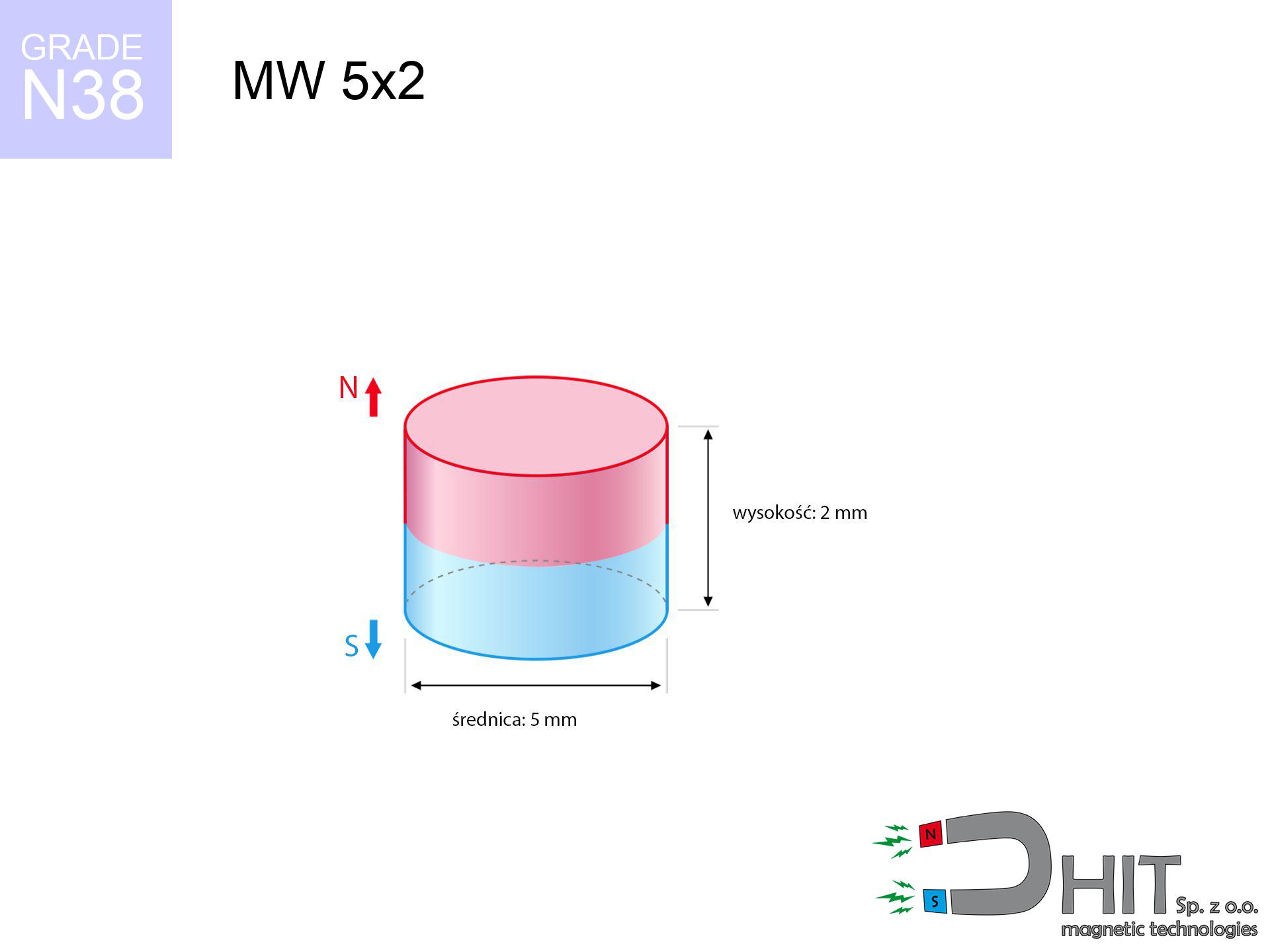
MW 5x2 / N38 - cylindrical magnet
cylindrical magnet
Catalog no 010085
GTIN/EAN: 5906301810841
Diameter Ø
5 mm [±0,1 mm]
Height
2 mm [±0,1 mm]
Weight
0.29 g
Magnetization Direction
↑ axial
Load capacity
0.70 kg / 6.83 N
Magnetic Induction
386.50 mT / 3865 Gs
Coating
[NiCuNi] Nickel
0.1845 ZŁ with VAT / pcs + price for transport
0.1500 ZŁ net + 23% VAT / pcs
bulk discounts:
Need more?Engineering report for this magnet
Full PDF analysis: pull and shear force, effect of distance, temperature and plate thickness, safety distances and the demagnetization curve.
Give us a call
+48 22 499 98 98
if you prefer drop us a message by means of
contact form
the contact section.
Lifting power along with structure of magnets can be checked on our
modular calculator.
Orders submitted before 14:00 will be dispatched today!
Technical - MW 5x2 / N38 - cylindrical magnet
Specification / characteristics - MW 5x2 / N38 - cylindrical magnet
| properties | values |
|---|---|
| Cat. no. | 010085 |
| GTIN/EAN | 5906301810841 |
| Production/Distribution | Dhit sp. z o.o. |
| Country of origin | Poland / China / Germany |
| Customs code | 85059029 |
| Diameter Ø | 5 mm [±0,1 mm] |
| Height | 2 mm [±0,1 mm] |
| Weight | 0.29 g |
| Magnetization Direction | ↑ axial |
| Load capacity ~ ? | 0.70 kg / 6.83 N |
| Magnetic Induction ~ ? | 386.50 mT / 3865 Gs |
| Coating | [NiCuNi] Nickel |
| Manufacturing Tolerance | ±0.1 mm |
Magnetic properties of material N38
| properties | values | units |
|---|---|---|
| remenance Br [min. - max.] ? | 12.2-12.6 | kGs |
| remenance Br [min. - max.] ? | 1220-1260 | mT |
| coercivity bHc ? | 10.8-11.5 | kOe |
| coercivity bHc ? | 860-915 | kA/m |
| actual internal force iHc | ≥ 12 | kOe |
| actual internal force iHc | ≥ 955 | kA/m |
| energy density [min. - max.] ? | 36-38 | BH max MGOe |
| energy density [min. - max.] ? | 287-303 | BH max KJ/m |
| max. temperature ? | ≤ 80 | °C |
Physical properties of sintered neodymium magnets Nd2Fe14B at 20°C
| properties | values | units |
|---|---|---|
| Vickers hardness | ≥550 | Hv |
| Density | ≥7.4 | g/cm3 |
| Curie Temperature TC | 312 - 380 | °C |
| Curie Temperature TF | 593 - 716 | °F |
| Specific resistance | 150 | μΩ⋅cm |
| Bending strength | 250 | MPa |
| Compressive strength | 1000~1100 | MPa |
| Thermal expansion parallel (∥) to orientation (M) | (3-4) x 10-6 | °C-1 |
| Thermal expansion perpendicular (⊥) to orientation (M) | -(1-3) x 10-6 | °C-1 |
| Young's modulus | 1.7 x 10⁴ | kg/mm² |
Physical simulation of the magnet - report
The following data constitute the outcome of a engineering analysis. Results rely on algorithms for the class Nd2Fe14B. Real-world performance may deviate from the simulation results. Use these data as a preliminary roadmap during assembly planning.
Table 1: Static pull force (force vs gap) - interaction chart
MW 5x2 / N38
| Distance (mm) | Induction (Gauss) / mT | Pull Force (kg/lbs/g/N) | Risk Status |
|---|---|---|---|
| 0 mm |
3860 Gs
386.0 mT
|
0.70 kg / 1.54 pounds
700.0 g / 6.9 N
|
safe |
| 1 mm |
2460 Gs
246.0 mT
|
0.28 kg / 0.63 pounds
284.4 g / 2.8 N
|
safe |
| 2 mm |
1384 Gs
138.4 mT
|
0.09 kg / 0.20 pounds
90.0 g / 0.9 N
|
safe |
| 3 mm |
782 Gs
78.2 mT
|
0.03 kg / 0.06 pounds
28.8 g / 0.3 N
|
safe |
| 5 mm |
293 Gs
29.3 mT
|
0.00 kg / 0.01 pounds
4.0 g / 0.0 N
|
safe |
| 10 mm |
55 Gs
5.5 mT
|
0.00 kg / 0.00 pounds
0.1 g / 0.0 N
|
safe |
| 15 mm |
18 Gs
1.8 mT
|
0.00 kg / 0.00 pounds
0.0 g / 0.0 N
|
safe |
| 20 mm |
8 Gs
0.8 mT
|
0.00 kg / 0.00 pounds
0.0 g / 0.0 N
|
safe |
| 30 mm |
3 Gs
0.3 mT
|
0.00 kg / 0.00 pounds
0.0 g / 0.0 N
|
safe |
| 50 mm |
1 Gs
0.1 mT
|
0.00 kg / 0.00 pounds
0.0 g / 0.0 N
|
safe |
Table 2: Shear hold (vertical surface)
MW 5x2 / N38
| Distance (mm) | Friction coefficient | Pull Force (kg/lbs/g/N) |
|---|---|---|
| 0 mm | Stal (~0.2) |
0.14 kg / 0.31 pounds
140.0 g / 1.4 N
|
| 1 mm | Stal (~0.2) |
0.06 kg / 0.12 pounds
56.0 g / 0.5 N
|
| 2 mm | Stal (~0.2) |
0.02 kg / 0.04 pounds
18.0 g / 0.2 N
|
| 3 mm | Stal (~0.2) |
0.01 kg / 0.01 pounds
6.0 g / 0.1 N
|
| 5 mm | Stal (~0.2) |
0.00 kg / 0.00 pounds
0.0 g / 0.0 N
|
| 10 mm | Stal (~0.2) |
0.00 kg / 0.00 pounds
0.0 g / 0.0 N
|
| 15 mm | Stal (~0.2) |
0.00 kg / 0.00 pounds
0.0 g / 0.0 N
|
| 20 mm | Stal (~0.2) |
0.00 kg / 0.00 pounds
0.0 g / 0.0 N
|
| 30 mm | Stal (~0.2) |
0.00 kg / 0.00 pounds
0.0 g / 0.0 N
|
| 50 mm | Stal (~0.2) |
0.00 kg / 0.00 pounds
0.0 g / 0.0 N
|
Table 3: Wall mounting (shearing) - vertical pull
MW 5x2 / N38
| Surface type | Friction coefficient / % Mocy | Max load (kg/lbs/g/N) |
|---|---|---|
| Raw steel |
µ = 0.3
30% Nominalnej Siły
|
0.21 kg / 0.46 pounds
210.0 g / 2.1 N
|
| Painted steel (standard) |
µ = 0.2
20% Nominalnej Siły
|
0.14 kg / 0.31 pounds
140.0 g / 1.4 N
|
| Oily/slippery steel |
µ = 0.1
10% Nominalnej Siły
|
0.07 kg / 0.15 pounds
70.0 g / 0.7 N
|
| Magnet with anti-slip rubber |
µ = 0.5
50% Nominalnej Siły
|
0.35 kg / 0.77 pounds
350.0 g / 3.4 N
|
Table 4: Material efficiency (substrate influence) - sheet metal selection
MW 5x2 / N38
| Steel thickness (mm) | % power | Real pull force (kg/lbs/g/N) |
|---|---|---|
| 0.5 mm |
|
0.07 kg / 0.15 pounds
70.0 g / 0.7 N
|
| 1 mm |
|
0.18 kg / 0.39 pounds
175.0 g / 1.7 N
|
| 2 mm |
|
0.35 kg / 0.77 pounds
350.0 g / 3.4 N
|
| 3 mm |
|
0.52 kg / 1.16 pounds
525.0 g / 5.2 N
|
| 5 mm |
|
0.70 kg / 1.54 pounds
700.0 g / 6.9 N
|
| 10 mm |
|
0.70 kg / 1.54 pounds
700.0 g / 6.9 N
|
| 11 mm |
|
0.70 kg / 1.54 pounds
700.0 g / 6.9 N
|
| 12 mm |
|
0.70 kg / 1.54 pounds
700.0 g / 6.9 N
|
Table 5: Thermal stability (material behavior) - power drop
MW 5x2 / N38
| Ambient temp. (°C) | Power loss | Remaining pull (kg/lbs/g/N) | Status |
|---|---|---|---|
| 20 °C | 0.0% |
0.70 kg / 1.54 pounds
700.0 g / 6.9 N
|
OK |
| 40 °C | -2.2% |
0.68 kg / 1.51 pounds
684.6 g / 6.7 N
|
OK |
| 60 °C | -4.4% |
0.67 kg / 1.48 pounds
669.2 g / 6.6 N
|
|
| 80 °C | -6.6% |
0.65 kg / 1.44 pounds
653.8 g / 6.4 N
|
|
| 100 °C | -28.8% |
0.50 kg / 1.10 pounds
498.4 g / 4.9 N
|
Table 6: Magnet-Magnet interaction (repulsion) - forces in the system
MW 5x2 / N38
| Gap (mm) | Attraction (kg/lbs) (N-S) | Shear Strength (kg/lbs/g/N) | Repulsion (kg/lbs) (N-N) |
|---|---|---|---|
| 0 mm |
1.80 kg / 3.98 pounds
5 236 Gs
|
0.27 kg / 0.60 pounds
271 g / 2.7 N
|
N/A |
| 1 mm |
1.21 kg / 2.68 pounds
6 336 Gs
|
0.18 kg / 0.40 pounds
182 g / 1.8 N
|
1.09 kg / 2.41 pounds
~0 Gs
|
| 2 mm |
0.73 kg / 1.62 pounds
4 921 Gs
|
0.11 kg / 0.24 pounds
110 g / 1.1 N
|
0.66 kg / 1.45 pounds
~0 Gs
|
| 3 mm |
0.42 kg / 0.92 pounds
3 711 Gs
|
0.06 kg / 0.14 pounds
62 g / 0.6 N
|
0.37 kg / 0.83 pounds
~0 Gs
|
| 5 mm |
0.13 kg / 0.29 pounds
2 071 Gs
|
0.02 kg / 0.04 pounds
19 g / 0.2 N
|
0.12 kg / 0.26 pounds
~0 Gs
|
| 10 mm |
0.01 kg / 0.02 pounds
587 Gs
|
0.00 kg / 0.00 pounds
2 g / 0.0 N
|
0.01 kg / 0.02 pounds
~0 Gs
|
| 20 mm |
0.00 kg / 0.00 pounds
110 Gs
|
0.00 kg / 0.00 pounds
0 g / 0.0 N
|
0.00 kg / 0.00 pounds
~0 Gs
|
| 50 mm |
0.00 kg / 0.00 pounds
9 Gs
|
0.00 kg / 0.00 pounds
0 g / 0.0 N
|
0.00 kg / 0.00 pounds
~0 Gs
|
| 60 mm |
0.00 kg / 0.00 pounds
5 Gs
|
0.00 kg / 0.00 pounds
0 g / 0.0 N
|
0.00 kg / 0.00 pounds
~0 Gs
|
| 70 mm |
0.00 kg / 0.00 pounds
3 Gs
|
0.00 kg / 0.00 pounds
0 g / 0.0 N
|
0.00 kg / 0.00 pounds
~0 Gs
|
| 80 mm |
0.00 kg / 0.00 pounds
2 Gs
|
0.00 kg / 0.00 pounds
0 g / 0.0 N
|
0.00 kg / 0.00 pounds
~0 Gs
|
| 90 mm |
0.00 kg / 0.00 pounds
2 Gs
|
0.00 kg / 0.00 pounds
0 g / 0.0 N
|
0.00 kg / 0.00 pounds
~0 Gs
|
| 100 mm |
0.00 kg / 0.00 pounds
1 Gs
|
0.00 kg / 0.00 pounds
0 g / 0.0 N
|
0.00 kg / 0.00 pounds
~0 Gs
|
Table 7: Safety (HSE) (implants) - precautionary measures
MW 5x2 / N38
| Object / Device | Limit (Gauss) / mT | Safe distance |
|---|---|---|
| Pacemaker | 5 Gs (0.5 mT) | 2.5 cm |
| Hearing aid | 10 Gs (1.0 mT) | 2.0 cm |
| Timepiece | 20 Gs (2.0 mT) | 1.5 cm |
| Mobile device | 40 Gs (4.0 mT) | 1.5 cm |
| Remote | 50 Gs (5.0 mT) | 1.5 cm |
| Payment card | 400 Gs (40.0 mT) | 0.5 cm |
| HDD hard drive | 600 Gs (60.0 mT) | 0.5 cm |
Table 8: Impact energy (cracking risk) - collision effects
MW 5x2 / N38
| Start from (mm) | Speed (km/h) | Energy (J) | Predicted outcome |
|---|---|---|---|
| 10 mm |
25.34 km/h
(7.04 m/s)
|
0.01 J | |
| 30 mm |
25.35 km/h
(7.04 m/s)
|
0.01 J | |
| 50 mm |
25.35 km/h
(7.04 m/s)
|
0.01 J | |
| 100 mm |
25.35 km/h
(7.04 m/s)
|
0.01 J |
Table 9: Coating parameters (durability)
MW 5x2 / N38
| Technical parameter | Value / Description |
|---|---|
| Coating type | [NiCuNi] Nickel |
| Layer structure | Nickel - Copper - Nickel |
| Layer thickness | 10-20 µm |
| Salt spray test (SST) ? | 24 h |
| Recommended environment | Indoors only (dry) |
Table 10: Electrical data (Flux)
MW 5x2 / N38
| Parameter | Value | SI Unit / Description |
|---|---|---|
| Magnetic Flux | 785 Mx | 7.9 µWb |
| Pc Coefficient | 0.50 | Low (Flat) |
Table 11: Hydrostatics and buoyancy
MW 5x2 / N38
| Environment | Effective steel pull | Effect |
|---|---|---|
| Air (land) | 0.70 kg | Standard |
| Water (riverbed) |
0.80 kg
(+0.10 kg buoyancy gain)
|
+14.5% |
1. Vertical hold
*Note: On a vertical surface, the magnet retains merely ~20% of its max power.
2. Steel thickness impact
*Thin steel (e.g. 0.5mm PC case) severely limits the holding force.
3. Temperature resistance
*For N38 material, the critical limit is 80°C.
4. Demagnetization curve and operating point (B-H)
chart generated for the permeance coefficient Pc (Permeance Coefficient) = 0.50
The chart above illustrates the magnetic characteristics of the material within the second quadrant of the hysteresis loop. The solid red line represents the demagnetization curve (material potential), while the dashed blue line is the load line based on the magnet's geometry. The Pc (Permeance Coefficient), also known as the load line slope, is a dimensionless value that describes the relationship between the magnet's shape and its magnetic stability. The intersection of these two lines (the black dot) is the operating point — it determines the actual magnetic flux density generated by the magnet in this specific configuration. A higher Pc value means the magnet is more 'slender' (tall relative to its area), resulting in a higher operating point and better resistance to irreversible demagnetization caused by external fields or temperature. A value of 0.42 is relatively low (typical for flat magnets), meaning the operating point is closer to the 'knee' of the curve — caution is advised when operating at temperatures near the maximum limit to avoid strength loss.
Elemental analysis
| iron (Fe) | 64% – 68% |
| neodymium (Nd) | 29% – 32% |
| boron (B) | 1.1% – 1.2% |
| dysprosium (Dy) | 0.5% – 2.0% |
| coating (Ni-Cu-Ni) | < 0.05% |
Ecology and recycling (GPSR)
| recyclability (EoL) | 100% |
| recycled raw materials | ~10% (pre-cons) |
| carbon footprint | low / zredukowany |
| waste code (EWC) | 16 02 16 |
Other offers


![UMGGW 22x6 [M4] GW / N38 - magnetic holder rubber internal thread](https://cdn3.dhit.pl/graphics/products/umg-22x6-m4-gw-jek.jpg "UMGGW 22x6 [M4] GW / N38 - magnetic holder rubber internal thread")
![SM 32x325 [2xM8] / N52 - magnetic separator](https://cdn3.dhit.pl/graphics/products/sm-32x325-2xm8-xec.jpg "SM 32x325 [2xM8] / N52 - magnetic separator")
Advantages as well as disadvantages of neodymium magnets.
Benefits
- Their strength is durable, and after approximately ten years it drops only by ~1% (according to research),
- Neodymium magnets are characterized by exceptionally resistant to loss of magnetic properties caused by external interference,
- In other words, due to the metallic surface of nickel, the element is aesthetically pleasing,
- Magnets are distinguished by extremely high magnetic induction on the active area,
- Made from properly selected components, these magnets show impressive resistance to high heat, enabling them to function (depending on their shape) at temperatures up to 230°C and above...
- Thanks to flexibility in constructing and the ability to customize to specific needs,
- Wide application in advanced technology sectors – they are used in computer drives, electromotive mechanisms, medical devices, also industrial machines.
- Relatively small size with high pulling force – neodymium magnets offer strong magnetic field in compact dimensions, which allows their use in compact constructions
Limitations
- Brittleness is one of their disadvantages. Upon intense impact they can break. We recommend keeping them in a strong case, which not only protects them against impacts but also increases their durability
- Neodymium magnets lose their force under the influence of heating. As soon as 80°C is exceeded, many of them start losing their power. Therefore, we recommend our special magnets marked [AH], which maintain durability even at temperatures up to 230°C
- They rust in a humid environment. For use outdoors we recommend using waterproof magnets e.g. in rubber, plastic
- We suggest casing - magnetic mount, due to difficulties in creating nuts inside the magnet and complex forms.
- Possible danger resulting from small fragments of magnets can be dangerous, when accidentally swallowed, which becomes key in the aspect of protecting the youngest. Additionally, small components of these magnets can disrupt the diagnostic process medical in case of swallowing.
- Due to neodymium price, their price is higher than average,
Pull force analysis
Maximum lifting capacity of the magnet – what contributes to it?
- with the use of a yoke made of low-carbon steel, ensuring maximum field concentration
- possessing a massiveness of minimum 10 mm to avoid saturation
- with an ideally smooth contact surface
- under conditions of gap-free contact (metal-to-metal)
- for force acting at a right angle (pull-off, not shear)
- at standard ambient temperature
Key elements affecting lifting force
- Distance – the presence of any layer (rust, dirt, gap) interrupts the magnetic circuit, which lowers power rapidly (even by 50% at 0.5 mm).
- Loading method – catalog parameter refers to detachment vertically. When slipping, the magnet exhibits much less (typically approx. 20-30% of maximum force).
- Substrate thickness – to utilize 100% power, the steel must be adequately massive. Thin sheet restricts the attraction force (the magnet "punches through" it).
- Material composition – not every steel reacts the same. High carbon content weaken the attraction effect.
- Surface quality – the smoother and more polished the plate, the better the adhesion and stronger the hold. Unevenness creates an air distance.
- Temperature – heating the magnet results in weakening of force. It is worth remembering the thermal limit for a given model.
Holding force was measured on a smooth steel plate of 20 mm thickness, when the force acted perpendicularly, in contrast under parallel forces the lifting capacity is smaller. In addition, even a slight gap between the magnet’s surface and the plate decreases the lifting capacity.
Safe handling of NdFeB magnets
Hand protection
Big blocks can break fingers instantly. Do not place your hand betwixt two attracting surfaces.
This is not a toy
Product intended for adults. Small elements pose a choking risk, causing intestinal necrosis. Store away from kids and pets.
Keep away from computers
Equipment safety: Neodymium magnets can damage data carriers and delicate electronics (pacemakers, hearing aids, timepieces).
Material brittleness
Protect your eyes. Magnets can fracture upon violent connection, ejecting sharp fragments into the air. Eye protection is mandatory.
Magnetic interference
Note: neodymium magnets generate a field that disrupts precision electronics. Maintain a separation from your phone, tablet, and GPS.
Respect the power
Before use, check safety instructions. Sudden snapping can break the magnet or injure your hand. Think ahead.
Pacemakers
Medical warning: Strong magnets can turn off heart devices and defibrillators. Stay away if you have medical devices.
Demagnetization risk
Control the heat. Heating the magnet to high heat will destroy its properties and strength.
Fire risk
Dust created during grinding of magnets is flammable. Do not drill into magnets unless you are an expert.
Sensitization to coating
A percentage of the population experience a hypersensitivity to Ni, which is the standard coating for neodymium magnets. Frequent touching might lead to an allergic reaction. We recommend wear safety gloves.
Tabela kosztu i czasu dostawy
Płatność przed wysyłką:

GLS kurier
Przesyłka będzie u Ciebie za 2-3 dni
14.99 ZŁ

InPost Paczkomaty 24/7
Przesyłka będzie u Ciebie za 1-2 dni
12.30 ZŁ
Płatność przy odbiorze (pobranie):
GLS kurier
Przesyłka będzie u Ciebie za 1-2 dni
23.00 ZŁ
Rate the product
Your rating