
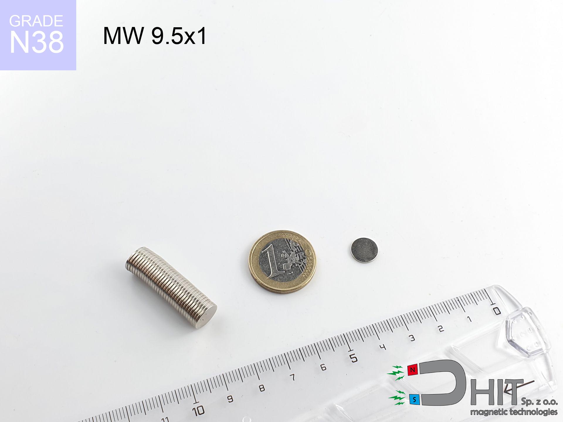
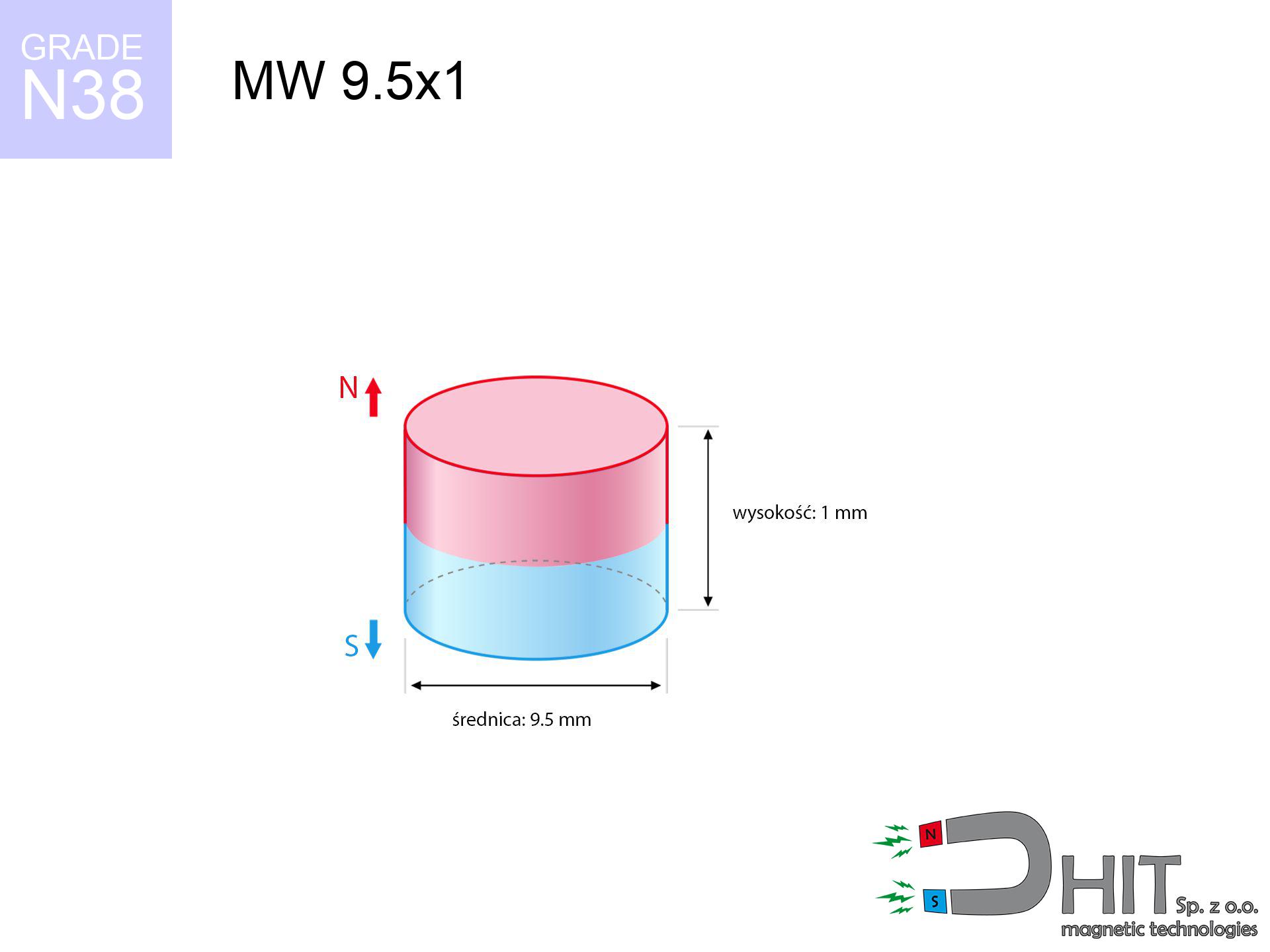
MW 9.5x1 / N38 - cylindrical magnet
cylindrical magnet
Catalog no 010107
GTIN/EAN: 5906301811060
Diameter Ø
9.5 mm [±0,1 mm]
Height
1 mm [±0,1 mm]
Weight
0.53 g
Magnetization Direction
↑ axial
Load capacity
0.40 kg / 3.96 N
Magnetic Induction
127.68 mT / 1277 Gs
Coating
[NiCuNi] Nickel
0.295 ZŁ with VAT / pcs + price for transport
0.240 ZŁ net + 23% VAT / pcs
bulk discounts:
Need more?
Pick up the phone and ask
+48 888 99 98 98
if you prefer let us know using
request form
the contact form page.
Force as well as appearance of neodymium magnets can be analyzed using our
modular calculator.
Orders submitted before 14:00 will be dispatched today!
Technical of the product - MW 9.5x1 / N38 - cylindrical magnet
Specification / characteristics - MW 9.5x1 / N38 - cylindrical magnet
| properties | values |
|---|---|
| Cat. no. | 010107 |
| GTIN/EAN | 5906301811060 |
| Production/Distribution | Dhit sp. z o.o. |
| Country of origin | Poland / China / Germany |
| Customs code | 85059029 |
| Diameter Ø | 9.5 mm [±0,1 mm] |
| Height | 1 mm [±0,1 mm] |
| Weight | 0.53 g |
| Magnetization Direction | ↑ axial |
| Load capacity ~ ? | 0.40 kg / 3.96 N |
| Magnetic Induction ~ ? | 127.68 mT / 1277 Gs |
| Coating | [NiCuNi] Nickel |
| Manufacturing Tolerance | ±0.1 mm |
Magnetic properties of material N38
| properties | values | units |
|---|---|---|
| remenance Br [min. - max.] ? | 12.2-12.6 | kGs |
| remenance Br [min. - max.] ? | 1220-1260 | mT |
| coercivity bHc ? | 10.8-11.5 | kOe |
| coercivity bHc ? | 860-915 | kA/m |
| actual internal force iHc | ≥ 12 | kOe |
| actual internal force iHc | ≥ 955 | kA/m |
| energy density [min. - max.] ? | 36-38 | BH max MGOe |
| energy density [min. - max.] ? | 287-303 | BH max KJ/m |
| max. temperature ? | ≤ 80 | °C |
Physical properties of sintered neodymium magnets Nd2Fe14B at 20°C
| properties | values | units |
|---|---|---|
| Vickers hardness | ≥550 | Hv |
| Density | ≥7.4 | g/cm3 |
| Curie Temperature TC | 312 - 380 | °C |
| Curie Temperature TF | 593 - 716 | °F |
| Specific resistance | 150 | μΩ⋅cm |
| Bending strength | 250 | MPa |
| Compressive strength | 1000~1100 | MPa |
| Thermal expansion parallel (∥) to orientation (M) | (3-4) x 10-6 | °C-1 |
| Thermal expansion perpendicular (⊥) to orientation (M) | -(1-3) x 10-6 | °C-1 |
| Young's modulus | 1.7 x 10⁴ | kg/mm² |
Engineering simulation of the magnet - report
The following data are the direct effect of a engineering simulation. Results were calculated on algorithms for the material Nd2Fe14B. Actual performance might slightly differ from theoretical values. Treat these data as a reference point during assembly planning.
Table 1: Static pull force (pull vs distance) - characteristics
MW 9.5x1 / N38
| Distance (mm) | Induction (Gauss) / mT | Pull Force (kg/lbs/g/N) | Risk Status |
|---|---|---|---|
| 0 mm |
1276 Gs
127.6 mT
|
0.40 kg / 0.88 LBS
400.0 g / 3.9 N
|
safe |
| 1 mm |
1129 Gs
112.9 mT
|
0.31 kg / 0.69 LBS
312.8 g / 3.1 N
|
safe |
| 2 mm |
905 Gs
90.5 mT
|
0.20 kg / 0.44 LBS
201.0 g / 2.0 N
|
safe |
| 3 mm |
683 Gs
68.3 mT
|
0.11 kg / 0.25 LBS
114.5 g / 1.1 N
|
safe |
| 5 mm |
366 Gs
36.6 mT
|
0.03 kg / 0.07 LBS
32.9 g / 0.3 N
|
safe |
| 10 mm |
92 Gs
9.2 mT
|
0.00 kg / 0.00 LBS
2.1 g / 0.0 N
|
safe |
| 15 mm |
33 Gs
3.3 mT
|
0.00 kg / 0.00 LBS
0.3 g / 0.0 N
|
safe |
| 20 mm |
15 Gs
1.5 mT
|
0.00 kg / 0.00 LBS
0.1 g / 0.0 N
|
safe |
| 30 mm |
5 Gs
0.5 mT
|
0.00 kg / 0.00 LBS
0.0 g / 0.0 N
|
safe |
| 50 mm |
1 Gs
0.1 mT
|
0.00 kg / 0.00 LBS
0.0 g / 0.0 N
|
safe |
Table 2: Sliding hold (wall)
MW 9.5x1 / N38
| Distance (mm) | Friction coefficient | Pull Force (kg/lbs/g/N) |
|---|---|---|
| 0 mm | Stal (~0.2) |
0.08 kg / 0.18 LBS
80.0 g / 0.8 N
|
| 1 mm | Stal (~0.2) |
0.06 kg / 0.14 LBS
62.0 g / 0.6 N
|
| 2 mm | Stal (~0.2) |
0.04 kg / 0.09 LBS
40.0 g / 0.4 N
|
| 3 mm | Stal (~0.2) |
0.02 kg / 0.05 LBS
22.0 g / 0.2 N
|
| 5 mm | Stal (~0.2) |
0.01 kg / 0.01 LBS
6.0 g / 0.1 N
|
| 10 mm | Stal (~0.2) |
0.00 kg / 0.00 LBS
0.0 g / 0.0 N
|
| 15 mm | Stal (~0.2) |
0.00 kg / 0.00 LBS
0.0 g / 0.0 N
|
| 20 mm | Stal (~0.2) |
0.00 kg / 0.00 LBS
0.0 g / 0.0 N
|
| 30 mm | Stal (~0.2) |
0.00 kg / 0.00 LBS
0.0 g / 0.0 N
|
| 50 mm | Stal (~0.2) |
0.00 kg / 0.00 LBS
0.0 g / 0.0 N
|
Table 3: Wall mounting (sliding) - behavior on slippery surfaces
MW 9.5x1 / N38
| Surface type | Friction coefficient / % Mocy | Max load (kg/lbs/g/N) |
|---|---|---|
| Raw steel |
µ = 0.3
30% Nominalnej Siły
|
0.12 kg / 0.26 LBS
120.0 g / 1.2 N
|
| Painted steel (standard) |
µ = 0.2
20% Nominalnej Siły
|
0.08 kg / 0.18 LBS
80.0 g / 0.8 N
|
| Oily/slippery steel |
µ = 0.1
10% Nominalnej Siły
|
0.04 kg / 0.09 LBS
40.0 g / 0.4 N
|
| Magnet with anti-slip rubber |
µ = 0.5
50% Nominalnej Siły
|
0.20 kg / 0.44 LBS
200.0 g / 2.0 N
|
Table 4: Steel thickness (substrate influence) - power losses
MW 9.5x1 / N38
| Steel thickness (mm) | % power | Real pull force (kg/lbs/g/N) |
|---|---|---|
| 0.5 mm |
|
0.04 kg / 0.09 LBS
40.0 g / 0.4 N
|
| 1 mm |
|
0.10 kg / 0.22 LBS
100.0 g / 1.0 N
|
| 2 mm |
|
0.20 kg / 0.44 LBS
200.0 g / 2.0 N
|
| 3 mm |
|
0.30 kg / 0.66 LBS
300.0 g / 2.9 N
|
| 5 mm |
|
0.40 kg / 0.88 LBS
400.0 g / 3.9 N
|
| 10 mm |
|
0.40 kg / 0.88 LBS
400.0 g / 3.9 N
|
| 11 mm |
|
0.40 kg / 0.88 LBS
400.0 g / 3.9 N
|
| 12 mm |
|
0.40 kg / 0.88 LBS
400.0 g / 3.9 N
|
Table 5: Thermal resistance (material behavior) - thermal limit
MW 9.5x1 / N38
| Ambient temp. (°C) | Power loss | Remaining pull (kg/lbs/g/N) | Status |
|---|---|---|---|
| 20 °C | 0.0% |
0.40 kg / 0.88 LBS
400.0 g / 3.9 N
|
OK |
| 40 °C | -2.2% |
0.39 kg / 0.86 LBS
391.2 g / 3.8 N
|
OK |
| 60 °C | -4.4% |
0.38 kg / 0.84 LBS
382.4 g / 3.8 N
|
|
| 80 °C | -6.6% |
0.37 kg / 0.82 LBS
373.6 g / 3.7 N
|
|
| 100 °C | -28.8% |
0.28 kg / 0.63 LBS
284.8 g / 2.8 N
|
Table 6: Magnet-Magnet interaction (repulsion) - field range
MW 9.5x1 / N38
| Gap (mm) | Attraction (kg/lbs) (N-S) | Sliding Force (kg/lbs/g/N) | Repulsion (kg/lbs) (N-N) |
|---|---|---|---|
| 0 mm |
0.71 kg / 1.57 LBS
2 403 Gs
|
0.11 kg / 0.24 LBS
107 g / 1.0 N
|
N/A |
| 1 mm |
0.65 kg / 1.43 LBS
2 436 Gs
|
0.10 kg / 0.21 LBS
97 g / 1.0 N
|
0.58 kg / 1.29 LBS
~0 Gs
|
| 2 mm |
0.56 kg / 1.23 LBS
2 257 Gs
|
0.08 kg / 0.18 LBS
84 g / 0.8 N
|
0.50 kg / 1.10 LBS
~0 Gs
|
| 3 mm |
0.46 kg / 1.00 LBS
2 041 Gs
|
0.07 kg / 0.15 LBS
68 g / 0.7 N
|
0.41 kg / 0.90 LBS
~0 Gs
|
| 5 mm |
0.27 kg / 0.60 LBS
1 580 Gs
|
0.04 kg / 0.09 LBS
41 g / 0.4 N
|
0.25 kg / 0.54 LBS
~0 Gs
|
| 10 mm |
0.06 kg / 0.13 LBS
732 Gs
|
0.01 kg / 0.02 LBS
9 g / 0.1 N
|
0.05 kg / 0.12 LBS
~0 Gs
|
| 20 mm |
0.00 kg / 0.01 LBS
183 Gs
|
0.00 kg / 0.00 LBS
1 g / 0.0 N
|
0.00 kg / 0.00 LBS
~0 Gs
|
| 50 mm |
0.00 kg / 0.00 LBS
16 Gs
|
0.00 kg / 0.00 LBS
0 g / 0.0 N
|
0.00 kg / 0.00 LBS
~0 Gs
|
| 60 mm |
0.00 kg / 0.00 LBS
10 Gs
|
0.00 kg / 0.00 LBS
0 g / 0.0 N
|
0.00 kg / 0.00 LBS
~0 Gs
|
| 70 mm |
0.00 kg / 0.00 LBS
6 Gs
|
0.00 kg / 0.00 LBS
0 g / 0.0 N
|
0.00 kg / 0.00 LBS
~0 Gs
|
| 80 mm |
0.00 kg / 0.00 LBS
4 Gs
|
0.00 kg / 0.00 LBS
0 g / 0.0 N
|
0.00 kg / 0.00 LBS
~0 Gs
|
| 90 mm |
0.00 kg / 0.00 LBS
3 Gs
|
0.00 kg / 0.00 LBS
0 g / 0.0 N
|
0.00 kg / 0.00 LBS
~0 Gs
|
| 100 mm |
0.00 kg / 0.00 LBS
2 Gs
|
0.00 kg / 0.00 LBS
0 g / 0.0 N
|
0.00 kg / 0.00 LBS
~0 Gs
|
Table 7: Hazards (implants) - precautionary measures
MW 9.5x1 / N38
| Object / Device | Limit (Gauss) / mT | Safe distance |
|---|---|---|
| Pacemaker | 5 Gs (0.5 mT) | 3.0 cm |
| Hearing aid | 10 Gs (1.0 mT) | 2.5 cm |
| Mechanical watch | 20 Gs (2.0 mT) | 2.0 cm |
| Phone / Smartphone | 40 Gs (4.0 mT) | 1.5 cm |
| Car key | 50 Gs (5.0 mT) | 1.5 cm |
| Payment card | 400 Gs (40.0 mT) | 0.5 cm |
| HDD hard drive | 600 Gs (60.0 mT) | 0.5 cm |
Table 8: Impact energy (kinetic energy) - warning
MW 9.5x1 / N38
| Start from (mm) | Speed (km/h) | Energy (J) | Predicted outcome |
|---|---|---|---|
| 10 mm |
27.80 km/h
(7.72 m/s)
|
0.02 J | |
| 30 mm |
47.99 km/h
(13.33 m/s)
|
0.05 J | |
| 50 mm |
61.95 km/h
(17.21 m/s)
|
0.08 J | |
| 100 mm |
87.61 km/h
(24.34 m/s)
|
0.16 J |
Table 9: Surface protection spec
MW 9.5x1 / N38
| Technical parameter | Value / Description |
|---|---|
| Coating type | [NiCuNi] Nickel |
| Layer structure | Nickel - Copper - Nickel |
| Layer thickness | 10-20 µm |
| Salt spray test (SST) ? | 24 h |
| Recommended environment | Indoors only (dry) |
Table 10: Electrical data (Flux)
MW 9.5x1 / N38
| Parameter | Value | SI Unit / Description |
|---|---|---|
| Magnetic Flux | 1 184 Mx | 11.8 µWb |
| Pc Coefficient | 0.16 | Low (Flat) |
Table 11: Physics of underwater searching
MW 9.5x1 / N38
| Environment | Effective steel pull | Effect |
|---|---|---|
| Air (land) | 0.40 kg | Standard |
| Water (riverbed) |
0.46 kg
(+0.06 kg buoyancy gain)
|
+14.5% |
1. Wall mount (shear)
*Caution: On a vertical wall, the magnet retains only approx. 20-30% of its max power.
2. Efficiency vs thickness
*Thin metal sheet (e.g. 0.5mm PC case) severely reduces the holding force.
3. Power loss vs temp
*For N38 material, the critical limit is 80°C.
4. Demagnetization curve and operating point (B-H)
chart generated for the permeance coefficient Pc (Permeance Coefficient) = 0.16
The chart above illustrates the magnetic characteristics of the material within the second quadrant of the hysteresis loop. The solid red line represents the demagnetization curve (material potential), while the dashed blue line is the load line based on the magnet's geometry. The Pc (Permeance Coefficient), also known as the load line slope, is a dimensionless value that describes the relationship between the magnet's shape and its magnetic stability. The intersection of these two lines (the black dot) is the operating point — it determines the actual magnetic flux density generated by the magnet in this specific configuration. A higher Pc value means the magnet is more 'slender' (tall relative to its area), resulting in a higher operating point and better resistance to irreversible demagnetization caused by external fields or temperature. A value of 0.42 is relatively low (typical for flat magnets), meaning the operating point is closer to the 'knee' of the curve — caution is advised when operating at temperatures near the maximum limit to avoid strength loss.
Material specification
| iron (Fe) | 64% – 68% |
| neodymium (Nd) | 29% – 32% |
| boron (B) | 1.1% – 1.2% |
| dysprosium (Dy) | 0.5% – 2.0% |
| coating (Ni-Cu-Ni) | < 0.05% |
Ecology and recycling (GPSR)
| recyclability (EoL) | 100% |
| recycled raw materials | ~10% (pre-cons) |
| carbon footprint | low / zredukowany |
| waste code (EWC) | 16 02 16 |
Check out also proposals


![SM 32x150 [2xM8] / N52 - magnetic separator](https://cdn3.dhit.pl/graphics/products/sm-32x150-2xm8-xuc.jpg "SM 32x150 [2xM8] / N52 - magnetic separator")
Advantages and disadvantages of neodymium magnets.
Strengths
- They do not lose strength, even over around ten years – the reduction in power is only ~1% (according to tests),
- Neodymium magnets are exceptionally resistant to demagnetization caused by external magnetic fields,
- By applying a smooth layer of silver, the element presents an elegant look,
- They are known for high magnetic induction at the operating surface, which increases their power,
- Due to their durability and thermal resistance, neodymium magnets can operate (depending on the form) even at high temperatures reaching 230°C or more...
- Thanks to freedom in shaping and the capacity to adapt to client solutions,
- Huge importance in modern technologies – they are commonly used in data components, electric drive systems, diagnostic systems, and industrial machines.
- Relatively small size with high pulling force – neodymium magnets offer high power in small dimensions, which allows their use in compact constructions
Cons
- To avoid cracks upon strong impacts, we suggest using special steel holders. Such a solution secures the magnet and simultaneously increases its durability.
- NdFeB magnets lose force when exposed to high temperatures. After reaching 80°C, many of them experience permanent weakening of power (a factor is the shape and dimensions of the magnet). We offer magnets specially adapted to work at temperatures up to 230°C marked [AH], which are very resistant to heat
- Due to the susceptibility of magnets to corrosion in a humid environment, we suggest using waterproof magnets made of rubber, plastic or other material stable to moisture, in case of application outdoors
- We recommend casing - magnetic mount, due to difficulties in creating threads inside the magnet and complex shapes.
- Health risk to health – tiny shards of magnets are risky, if swallowed, which is particularly important in the aspect of protecting the youngest. Additionally, tiny parts of these devices can disrupt the diagnostic process medical in case of swallowing.
- High unit price – neodymium magnets have a higher price than other types of magnets (e.g. ferrite), which can limit application in large quantities
Lifting parameters
Best holding force of the magnet in ideal parameters – what contributes to it?
- using a plate made of low-carbon steel, acting as a circuit closing element
- with a cross-section of at least 10 mm
- with an ground contact surface
- under conditions of ideal adhesion (metal-to-metal)
- under vertical force direction (90-degree angle)
- at standard ambient temperature
Impact of factors on magnetic holding capacity in practice
- Gap between surfaces – every millimeter of separation (caused e.g. by varnish or unevenness) significantly weakens the pulling force, often by half at just 0.5 mm.
- Loading method – catalog parameter refers to pulling vertically. When attempting to slide, the magnet holds much less (typically approx. 20-30% of maximum force).
- Substrate thickness – to utilize 100% power, the steel must be sufficiently thick. Paper-thin metal limits the attraction force (the magnet "punches through" it).
- Material type – ideal substrate is high-permeability steel. Cast iron may have worse magnetic properties.
- Surface structure – the smoother and more polished the surface, the larger the contact zone and stronger the hold. Unevenness creates an air distance.
- Thermal factor – high temperature weakens magnetic field. Too high temperature can permanently damage the magnet.
Holding force was tested on the plate surface of 20 mm thickness, when the force acted perpendicularly, whereas under shearing force the holding force is lower. Additionally, even a small distance between the magnet’s surface and the plate decreases the holding force.
Warnings
Fire risk
Combustion risk: Rare earth powder is highly flammable. Do not process magnets in home conditions as this risks ignition.
Life threat
Individuals with a pacemaker should maintain an safe separation from magnets. The magnetic field can interfere with the operation of the life-saving device.
Nickel coating and allergies
It is widely known that the nickel plating (the usual finish) is a common allergen. If your skin reacts to metals, avoid direct skin contact or opt for encased magnets.
Keep away from computers
Powerful magnetic fields can erase data on credit cards, hard drives, and storage devices. Keep a distance of at least 10 cm.
Pinching danger
Pinching hazard: The pulling power is so great that it can result in blood blisters, crushing, and broken bones. Protective gloves are recommended.
Operating temperature
Keep cool. NdFeB magnets are sensitive to temperature. If you need resistance above 80°C, look for special high-temperature series (H, SH, UH).
Compass and GPS
A strong magnetic field disrupts the operation of magnetometers in phones and navigation systems. Keep magnets close to a smartphone to prevent breaking the sensors.
This is not a toy
Neodymium magnets are not suitable for play. Eating multiple magnets may result in them attracting across intestines, which poses a severe health hazard and necessitates urgent medical intervention.
Do not underestimate power
Handle with care. Rare earth magnets attract from a distance and connect with huge force, often quicker than you can move away.
Fragile material
Despite metallic appearance, neodymium is delicate and not impact-resistant. Do not hit, as the magnet may shatter into hazardous fragments.
Tabela kosztu i czasu dostawy
Płatność przed wysyłką:

GLS kurier
Przesyłka będzie u Ciebie za 2-3 dni
14.99 ZŁ

InPost Paczkomaty 24/7
Przesyłka będzie u Ciebie za 1-2 dni
12.30 ZŁ
Płatność przy odbiorze (pobranie):
GLS kurier
Przesyłka będzie u Ciebie za 1-2 dni
23.00 ZŁ
Rate the product
Your rating