
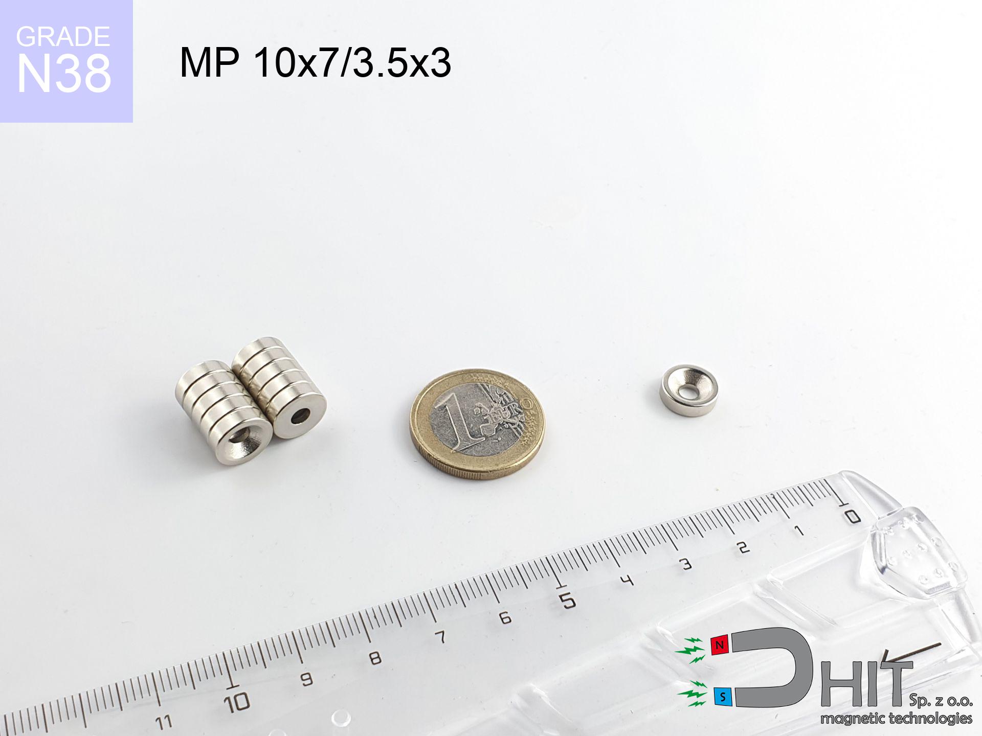
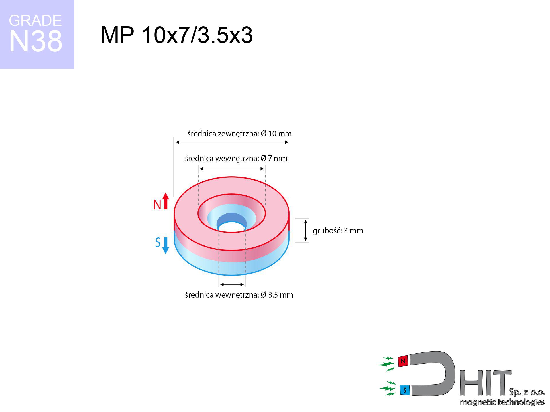
MP 10x7/3.5x3 / N38 - ring magnet
ring magnet
Catalog no 030180
GTIN/EAN: 5906301811978
Diameter
10 mm [±0,1 mm]
internal diameter Ø
7/3.5 mm [±0,1 mm]
Height
3 mm [±0,1 mm]
Weight
1.55 g
Magnetization Direction
↑ axial
Load capacity
1.88 kg / 18.47 N
Magnetic Induction
318.70 mT / 3187 Gs
Coating
[NiCuNi] Nickel
0.824 ZŁ with VAT / pcs + price for transport
0.670 ZŁ net + 23% VAT / pcs
bulk discounts:
Need more?
Call us now
+48 22 499 98 98
or contact us by means of
form
through our site.
Strength as well as structure of a neodymium magnet can be calculated with our
modular calculator.
Same-day processing for orders placed before 14:00.
Technical - MP 10x7/3.5x3 / N38 - ring magnet
Specification / characteristics - MP 10x7/3.5x3 / N38 - ring magnet
| properties | values |
|---|---|
| Cat. no. | 030180 |
| GTIN/EAN | 5906301811978 |
| Production/Distribution | Dhit sp. z o.o. |
| Country of origin | Poland / China / Germany |
| Customs code | 85059029 |
| Diameter | 10 mm [±0,1 mm] |
| internal diameter Ø | 7/3.5 mm [±0,1 mm] |
| Height | 3 mm [±0,1 mm] |
| Weight | 1.55 g |
| Magnetization Direction | ↑ axial |
| Load capacity ~ ? | 1.88 kg / 18.47 N |
| Magnetic Induction ~ ? | 318.70 mT / 3187 Gs |
| Coating | [NiCuNi] Nickel |
| Manufacturing Tolerance | ±0.1 mm |
Magnetic properties of material N38
| properties | values | units |
|---|---|---|
| remenance Br [min. - max.] ? | 12.2-12.6 | kGs |
| remenance Br [min. - max.] ? | 1220-1260 | mT |
| coercivity bHc ? | 10.8-11.5 | kOe |
| coercivity bHc ? | 860-915 | kA/m |
| actual internal force iHc | ≥ 12 | kOe |
| actual internal force iHc | ≥ 955 | kA/m |
| energy density [min. - max.] ? | 36-38 | BH max MGOe |
| energy density [min. - max.] ? | 287-303 | BH max KJ/m |
| max. temperature ? | ≤ 80 | °C |
Physical properties of sintered neodymium magnets Nd2Fe14B at 20°C
| properties | values | units |
|---|---|---|
| Vickers hardness | ≥550 | Hv |
| Density | ≥7.4 | g/cm3 |
| Curie Temperature TC | 312 - 380 | °C |
| Curie Temperature TF | 593 - 716 | °F |
| Specific resistance | 150 | μΩ⋅cm |
| Bending strength | 250 | MPa |
| Compressive strength | 1000~1100 | MPa |
| Thermal expansion parallel (∥) to orientation (M) | (3-4) x 10-6 | °C-1 |
| Thermal expansion perpendicular (⊥) to orientation (M) | -(1-3) x 10-6 | °C-1 |
| Young's modulus | 1.7 x 10⁴ | kg/mm² |
Engineering modeling of the product - data
The following information constitute the outcome of a physical analysis. Results are based on models for the class Nd2Fe14B. Actual conditions may deviate from the simulation results. Use these data as a preliminary roadmap for designers.
Table 1: Static force (force vs gap) - power drop
MP 10x7/3.5x3 / N38
| Distance (mm) | Induction (Gauss) / mT | Pull Force (kg/lbs/g/N) | Risk Status |
|---|---|---|---|
| 0 mm |
2813 Gs
281.3 mT
|
1.88 kg / 4.14 pounds
1880.0 g / 18.4 N
|
weak grip |
| 1 mm |
2373 Gs
237.3 mT
|
1.34 kg / 2.95 pounds
1338.1 g / 13.1 N
|
weak grip |
| 2 mm |
1870 Gs
187.0 mT
|
0.83 kg / 1.83 pounds
830.9 g / 8.2 N
|
weak grip |
| 3 mm |
1416 Gs
141.6 mT
|
0.48 kg / 1.05 pounds
476.6 g / 4.7 N
|
weak grip |
| 5 mm |
785 Gs
78.5 mT
|
0.15 kg / 0.32 pounds
146.4 g / 1.4 N
|
weak grip |
| 10 mm |
214 Gs
21.4 mT
|
0.01 kg / 0.02 pounds
10.9 g / 0.1 N
|
weak grip |
| 15 mm |
81 Gs
8.1 mT
|
0.00 kg / 0.00 pounds
1.6 g / 0.0 N
|
weak grip |
| 20 mm |
38 Gs
3.8 mT
|
0.00 kg / 0.00 pounds
0.3 g / 0.0 N
|
weak grip |
| 30 mm |
12 Gs
1.2 mT
|
0.00 kg / 0.00 pounds
0.0 g / 0.0 N
|
weak grip |
| 50 mm |
3 Gs
0.3 mT
|
0.00 kg / 0.00 pounds
0.0 g / 0.0 N
|
weak grip |
Table 2: Shear hold (vertical surface)
MP 10x7/3.5x3 / N38
| Distance (mm) | Friction coefficient | Pull Force (kg/lbs/g/N) |
|---|---|---|
| 0 mm | Stal (~0.2) |
0.38 kg / 0.83 pounds
376.0 g / 3.7 N
|
| 1 mm | Stal (~0.2) |
0.27 kg / 0.59 pounds
268.0 g / 2.6 N
|
| 2 mm | Stal (~0.2) |
0.17 kg / 0.37 pounds
166.0 g / 1.6 N
|
| 3 mm | Stal (~0.2) |
0.10 kg / 0.21 pounds
96.0 g / 0.9 N
|
| 5 mm | Stal (~0.2) |
0.03 kg / 0.07 pounds
30.0 g / 0.3 N
|
| 10 mm | Stal (~0.2) |
0.00 kg / 0.00 pounds
2.0 g / 0.0 N
|
| 15 mm | Stal (~0.2) |
0.00 kg / 0.00 pounds
0.0 g / 0.0 N
|
| 20 mm | Stal (~0.2) |
0.00 kg / 0.00 pounds
0.0 g / 0.0 N
|
| 30 mm | Stal (~0.2) |
0.00 kg / 0.00 pounds
0.0 g / 0.0 N
|
| 50 mm | Stal (~0.2) |
0.00 kg / 0.00 pounds
0.0 g / 0.0 N
|
Table 3: Vertical assembly (sliding) - vertical pull
MP 10x7/3.5x3 / N38
| Surface type | Friction coefficient / % Mocy | Max load (kg/lbs/g/N) |
|---|---|---|
| Raw steel |
µ = 0.3
30% Nominalnej Siły
|
0.56 kg / 1.24 pounds
564.0 g / 5.5 N
|
| Painted steel (standard) |
µ = 0.2
20% Nominalnej Siły
|
0.38 kg / 0.83 pounds
376.0 g / 3.7 N
|
| Oily/slippery steel |
µ = 0.1
10% Nominalnej Siły
|
0.19 kg / 0.41 pounds
188.0 g / 1.8 N
|
| Magnet with anti-slip rubber |
µ = 0.5
50% Nominalnej Siły
|
0.94 kg / 2.07 pounds
940.0 g / 9.2 N
|
Table 4: Material efficiency (substrate influence) - power losses
MP 10x7/3.5x3 / N38
| Steel thickness (mm) | % power | Real pull force (kg/lbs/g/N) |
|---|---|---|
| 0.5 mm |
|
0.19 kg / 0.41 pounds
188.0 g / 1.8 N
|
| 1 mm |
|
0.47 kg / 1.04 pounds
470.0 g / 4.6 N
|
| 2 mm |
|
0.94 kg / 2.07 pounds
940.0 g / 9.2 N
|
| 3 mm |
|
1.41 kg / 3.11 pounds
1410.0 g / 13.8 N
|
| 5 mm |
|
1.88 kg / 4.14 pounds
1880.0 g / 18.4 N
|
| 10 mm |
|
1.88 kg / 4.14 pounds
1880.0 g / 18.4 N
|
| 11 mm |
|
1.88 kg / 4.14 pounds
1880.0 g / 18.4 N
|
| 12 mm |
|
1.88 kg / 4.14 pounds
1880.0 g / 18.4 N
|
Table 5: Thermal stability (material behavior) - resistance threshold
MP 10x7/3.5x3 / N38
| Ambient temp. (°C) | Power loss | Remaining pull (kg/lbs/g/N) | Status |
|---|---|---|---|
| 20 °C | 0.0% |
1.88 kg / 4.14 pounds
1880.0 g / 18.4 N
|
OK |
| 40 °C | -2.2% |
1.84 kg / 4.05 pounds
1838.6 g / 18.0 N
|
OK |
| 60 °C | -4.4% |
1.80 kg / 3.96 pounds
1797.3 g / 17.6 N
|
|
| 80 °C | -6.6% |
1.76 kg / 3.87 pounds
1755.9 g / 17.2 N
|
|
| 100 °C | -28.8% |
1.34 kg / 2.95 pounds
1338.6 g / 13.1 N
|
Table 6: Magnet-Magnet interaction (repulsion) - forces in the system
MP 10x7/3.5x3 / N38
| Gap (mm) | Attraction (kg/lbs) (N-S) | Sliding Force (kg/lbs/g/N) | Repulsion (kg/lbs) (N-N) |
|---|---|---|---|
| 0 mm |
2.86 kg / 6.30 pounds
4 419 Gs
|
0.43 kg / 0.95 pounds
429 g / 4.2 N
|
N/A |
| 1 mm |
2.46 kg / 5.43 pounds
5 224 Gs
|
0.37 kg / 0.81 pounds
370 g / 3.6 N
|
2.22 kg / 4.89 pounds
~0 Gs
|
| 2 mm |
2.03 kg / 4.49 pounds
4 747 Gs
|
0.31 kg / 0.67 pounds
305 g / 3.0 N
|
1.83 kg / 4.04 pounds
~0 Gs
|
| 3 mm |
1.62 kg / 3.58 pounds
4 242 Gs
|
0.24 kg / 0.54 pounds
244 g / 2.4 N
|
1.46 kg / 3.22 pounds
~0 Gs
|
| 5 mm |
0.96 kg / 2.12 pounds
3 266 Gs
|
0.14 kg / 0.32 pounds
144 g / 1.4 N
|
0.87 kg / 1.91 pounds
~0 Gs
|
| 10 mm |
0.22 kg / 0.49 pounds
1 570 Gs
|
0.03 kg / 0.07 pounds
33 g / 0.3 N
|
0.20 kg / 0.44 pounds
~0 Gs
|
| 20 mm |
0.02 kg / 0.04 pounds
429 Gs
|
0.00 kg / 0.01 pounds
2 g / 0.0 N
|
0.01 kg / 0.03 pounds
~0 Gs
|
| 50 mm |
0.00 kg / 0.00 pounds
41 Gs
|
0.00 kg / 0.00 pounds
0 g / 0.0 N
|
0.00 kg / 0.00 pounds
~0 Gs
|
| 60 mm |
0.00 kg / 0.00 pounds
25 Gs
|
0.00 kg / 0.00 pounds
0 g / 0.0 N
|
0.00 kg / 0.00 pounds
~0 Gs
|
| 70 mm |
0.00 kg / 0.00 pounds
16 Gs
|
0.00 kg / 0.00 pounds
0 g / 0.0 N
|
0.00 kg / 0.00 pounds
~0 Gs
|
| 80 mm |
0.00 kg / 0.00 pounds
11 Gs
|
0.00 kg / 0.00 pounds
0 g / 0.0 N
|
0.00 kg / 0.00 pounds
~0 Gs
|
| 90 mm |
0.00 kg / 0.00 pounds
8 Gs
|
0.00 kg / 0.00 pounds
0 g / 0.0 N
|
0.00 kg / 0.00 pounds
~0 Gs
|
| 100 mm |
0.00 kg / 0.00 pounds
6 Gs
|
0.00 kg / 0.00 pounds
0 g / 0.0 N
|
0.00 kg / 0.00 pounds
~0 Gs
|
Table 7: Safety (HSE) (implants) - warnings
MP 10x7/3.5x3 / N38
| Object / Device | Limit (Gauss) / mT | Safe distance |
|---|---|---|
| Pacemaker | 5 Gs (0.5 mT) | 4.5 cm |
| Hearing aid | 10 Gs (1.0 mT) | 3.5 cm |
| Mechanical watch | 20 Gs (2.0 mT) | 3.0 cm |
| Mobile device | 40 Gs (4.0 mT) | 2.0 cm |
| Remote | 50 Gs (5.0 mT) | 2.0 cm |
| Payment card | 400 Gs (40.0 mT) | 1.0 cm |
| HDD hard drive | 600 Gs (60.0 mT) | 1.0 cm |
Table 8: Impact energy (kinetic energy) - collision effects
MP 10x7/3.5x3 / N38
| Start from (mm) | Speed (km/h) | Energy (J) | Predicted outcome |
|---|---|---|---|
| 10 mm |
35.25 km/h
(9.79 m/s)
|
0.07 J | |
| 30 mm |
60.84 km/h
(16.90 m/s)
|
0.22 J | |
| 50 mm |
78.54 km/h
(21.82 m/s)
|
0.37 J | |
| 100 mm |
111.07 km/h
(30.85 m/s)
|
0.74 J |
Table 9: Coating parameters (durability)
MP 10x7/3.5x3 / N38
| Technical parameter | Value / Description |
|---|---|
| Coating type | [NiCuNi] Nickel |
| Layer structure | Nickel - Copper - Nickel |
| Layer thickness | 10-20 µm |
| Salt spray test (SST) ? | 24 h |
| Recommended environment | Indoors only (dry) |
Table 10: Construction data (Flux)
MP 10x7/3.5x3 / N38
| Parameter | Value | SI Unit / Description |
|---|---|---|
| Magnetic Flux | 1 899 Mx | 19.0 µWb |
| Pc Coefficient | 0.37 | Low (Flat) |
Table 11: Hydrostatics and buoyancy
MP 10x7/3.5x3 / N38
| Environment | Effective steel pull | Effect |
|---|---|---|
| Air (land) | 1.88 kg | Standard |
| Water (riverbed) |
2.15 kg
(+0.27 kg buoyancy gain)
|
+14.5% |
1. Vertical hold
*Caution: On a vertical surface, the magnet retains only approx. 20-30% of its nominal pull.
2. Steel thickness impact
*Thin metal sheet (e.g. 0.5mm PC case) drastically limits the holding force.
3. Heat tolerance
*For standard magnets, the safety limit is 80°C.
4. Demagnetization curve and operating point (B-H)
chart generated for the permeance coefficient Pc (Permeance Coefficient) = 0.37
The chart above illustrates the magnetic characteristics of the material within the second quadrant of the hysteresis loop. The solid red line represents the demagnetization curve (material potential), while the dashed blue line is the load line based on the magnet's geometry. The Pc (Permeance Coefficient), also known as the load line slope, is a dimensionless value that describes the relationship between the magnet's shape and its magnetic stability. The intersection of these two lines (the black dot) is the operating point — it determines the actual magnetic flux density generated by the magnet in this specific configuration. A higher Pc value means the magnet is more 'slender' (tall relative to its area), resulting in a higher operating point and better resistance to irreversible demagnetization caused by external fields or temperature. A value of 0.42 is relatively low (typical for flat magnets), meaning the operating point is closer to the 'knee' of the curve — caution is advised when operating at temperatures near the maximum limit to avoid strength loss.
Material specification
| iron (Fe) | 64% – 68% |
| neodymium (Nd) | 29% – 32% |
| boron (B) | 1.1% – 1.2% |
| dysprosium (Dy) | 0.5% – 2.0% |
| coating (Ni-Cu-Ni) | < 0.05% |
Environmental data
| recyclability (EoL) | 100% |
| recycled raw materials | ~10% (pre-cons) |
| carbon footprint | low / zredukowany |
| waste code (EWC) | 16 02 16 |
Other proposals


![UMP 75x25 [M10x3] GW F200 GOLD DUAL / N42 - search holder](https://cdn3.dhit.pl/graphics/products/ump-75x25-m10x3-gw-f200-gold-dual-xoc.jpg "UMP 75x25 [M10x3] GW F200 GOLD DUAL / N42 - search holder")
Advantages and disadvantages of Nd2Fe14B magnets.
Benefits
- They retain full power for nearly ten years – the loss is just ~1% (based on simulations),
- They have excellent resistance to weakening of magnetic properties as a result of external fields,
- A magnet with a shiny nickel surface has better aesthetics,
- The surface of neodymium magnets generates a unique magnetic field – this is a key feature,
- Through (adequate) combination of ingredients, they can achieve high thermal resistance, enabling action at temperatures reaching 230°C and above...
- Possibility of exact forming as well as modifying to atypical applications,
- Universal use in advanced technology sectors – they are utilized in computer drives, electromotive mechanisms, precision medical tools, also multitasking production systems.
- Thanks to efficiency per cm³, small magnets offer high operating force, in miniature format,
Limitations
- To avoid cracks under impact, we recommend using special steel housings. Such a solution protects the magnet and simultaneously increases its durability.
- We warn that neodymium magnets can reduce their power at high temperatures. To prevent this, we advise our specialized [AH] magnets, which work effectively even at 230°C.
- Magnets exposed to a humid environment can corrode. Therefore during using outdoors, we suggest using water-impermeable magnets made of rubber, plastic or other material resistant to moisture
- We recommend cover - magnetic mechanism, due to difficulties in creating threads inside the magnet and complex forms.
- Possible danger resulting from small fragments of magnets pose a threat, in case of ingestion, which becomes key in the context of child health protection. Furthermore, small elements of these magnets are able to disrupt the diagnostic process medical in case of swallowing.
- High unit price – neodymium magnets cost more than other types of magnets (e.g. ferrite), which hinders application in large quantities
Lifting parameters
Breakaway strength of the magnet in ideal conditions – what contributes to it?
- on a plate made of mild steel, effectively closing the magnetic field
- possessing a massiveness of at least 10 mm to avoid saturation
- characterized by even structure
- without the slightest air gap between the magnet and steel
- for force acting at a right angle (pull-off, not shear)
- at room temperature
Impact of factors on magnetic holding capacity in practice
- Gap (between the magnet and the plate), since even a tiny clearance (e.g. 0.5 mm) leads to a reduction in force by up to 50% (this also applies to paint, rust or dirt).
- Load vector – highest force is reached only during perpendicular pulling. The force required to slide of the magnet along the surface is standardly several times smaller (approx. 1/5 of the lifting capacity).
- Metal thickness – the thinner the sheet, the weaker the hold. Magnetic flux penetrates through instead of generating force.
- Metal type – not every steel attracts identically. Alloy additives weaken the attraction effect.
- Surface structure – the more even the surface, the larger the contact zone and stronger the hold. Roughness acts like micro-gaps.
- Thermal environment – temperature increase results in weakening of induction. Check the maximum operating temperature for a given model.
Lifting capacity was determined by applying a polished steel plate of suitable thickness (min. 20 mm), under vertically applied force, however under shearing force the lifting capacity is smaller. Moreover, even a minimal clearance between the magnet’s surface and the plate lowers the load capacity.
Safety rules for work with NdFeB magnets
Danger to the youngest
These products are not toys. Accidental ingestion of a few magnets can lead to them attracting across intestines, which constitutes a critical condition and necessitates urgent medical intervention.
Demagnetization risk
Control the heat. Exposing the magnet to high heat will permanently weaken its magnetic structure and pulling force.
GPS and phone interference
A powerful magnetic field disrupts the operation of compasses in smartphones and navigation systems. Keep magnets close to a device to avoid breaking the sensors.
Safe distance
Intense magnetic fields can corrupt files on payment cards, hard drives, and other magnetic media. Stay away of at least 10 cm.
Handling guide
Be careful. Neodymium magnets act from a long distance and connect with massive power, often quicker than you can react.
Medical implants
People with a heart stimulator should keep an safe separation from magnets. The magnetic field can stop the operation of the implant.
Dust is flammable
Powder generated during machining of magnets is flammable. Do not drill into magnets unless you are an expert.
Allergy Warning
Certain individuals have a contact allergy to Ni, which is the typical protective layer for NdFeB magnets. Frequent touching might lead to dermatitis. We suggest wear safety gloves.
Bone fractures
Danger of trauma: The pulling power is so great that it can result in hematomas, pinching, and even bone fractures. Use thick gloves.
Beware of splinters
NdFeB magnets are ceramic materials, which means they are very brittle. Collision of two magnets will cause them breaking into shards.
Tabela kosztu i czasu dostawy
Płatność przed wysyłką:

GLS kurier
Przesyłka będzie u Ciebie za 2-3 dni
14.99 ZŁ

InPost Paczkomaty 24/7
Przesyłka będzie u Ciebie za 1-2 dni
12.30 ZŁ
Płatność przy odbiorze (pobranie):
GLS kurier
Przesyłka będzie u Ciebie za 1-2 dni
23.00 ZŁ
Rate the product
Your rating