
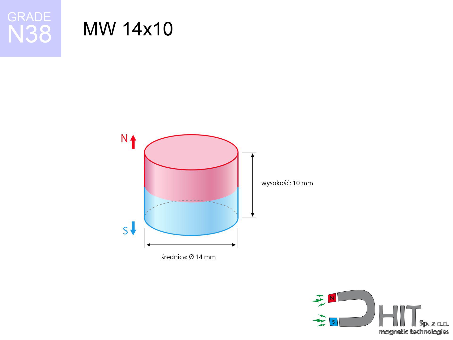
MW 14x10 / N38 - cylindrical magnet
cylindrical magnet
Catalog no 010391
GTIN/EAN: 5906301811084
Diameter Ø
14 mm [±0,1 mm]
Height
10 mm [±0,1 mm]
Weight
11.55 g
Magnetization Direction
↑ axial
Load capacity
6.71 kg / 65.83 N
Magnetic Induction
507.48 mT / 5075 Gs
Coating
[NiCuNi] Nickel
6.84 ZŁ with VAT / pcs + price for transport
5.56 ZŁ net + 23% VAT / pcs
bulk discounts:
Need more?Engineering report for this magnet
Full PDF analysis: pull and shear force, effect of distance, temperature and plate thickness, safety distances and the demagnetization curve.
Contact us by phone
+48 888 99 98 98
alternatively drop us a message through
contact form
our website.
Specifications and appearance of a magnet can be estimated using our
magnetic mass calculator.
Orders submitted before 14:00 will be dispatched today!
Technical details - MW 14x10 / N38 - cylindrical magnet
Specification / characteristics - MW 14x10 / N38 - cylindrical magnet
| properties | values |
|---|---|
| Cat. no. | 010391 |
| GTIN/EAN | 5906301811084 |
| Production/Distribution | Dhit sp. z o.o. |
| Country of origin | Poland / China / Germany |
| Customs code | 85059029 |
| Diameter Ø | 14 mm [±0,1 mm] |
| Height | 10 mm [±0,1 mm] |
| Weight | 11.55 g |
| Magnetization Direction | ↑ axial |
| Load capacity ~ ? | 6.71 kg / 65.83 N |
| Magnetic Induction ~ ? | 507.48 mT / 5075 Gs |
| Coating | [NiCuNi] Nickel |
| Manufacturing Tolerance | ±0.1 mm |
Magnetic properties of material N38
| properties | values | units |
|---|---|---|
| remenance Br [min. - max.] ? | 12.2-12.6 | kGs |
| remenance Br [min. - max.] ? | 1220-1260 | mT |
| coercivity bHc ? | 10.8-11.5 | kOe |
| coercivity bHc ? | 860-915 | kA/m |
| actual internal force iHc | ≥ 12 | kOe |
| actual internal force iHc | ≥ 955 | kA/m |
| energy density [min. - max.] ? | 36-38 | BH max MGOe |
| energy density [min. - max.] ? | 287-303 | BH max KJ/m |
| max. temperature ? | ≤ 80 | °C |
Physical properties of sintered neodymium magnets Nd2Fe14B at 20°C
| properties | values | units |
|---|---|---|
| Vickers hardness | ≥550 | Hv |
| Density | ≥7.4 | g/cm3 |
| Curie Temperature TC | 312 - 380 | °C |
| Curie Temperature TF | 593 - 716 | °F |
| Specific resistance | 150 | μΩ⋅cm |
| Bending strength | 250 | MPa |
| Compressive strength | 1000~1100 | MPa |
| Thermal expansion parallel (∥) to orientation (M) | (3-4) x 10-6 | °C-1 |
| Thermal expansion perpendicular (⊥) to orientation (M) | -(1-3) x 10-6 | °C-1 |
| Young's modulus | 1.7 x 10⁴ | kg/mm² |
Physical modeling of the assembly - data
Presented data represent the direct effect of a physical calculation. Values are based on models for the material Nd2Fe14B. Real-world conditions may differ. Please consider these calculations as a reference point for designers.
Table 1: Static pull force (pull vs gap) - power drop
MW 14x10 / N38
| Distance (mm) | Induction (Gauss) / mT | Pull Force (kg/lbs/g/N) | Risk Status |
|---|---|---|---|
| 0 mm |
5072 Gs
507.2 mT
|
6.71 kg / 14.79 pounds
6710.0 g / 65.8 N
|
medium risk |
| 1 mm |
4354 Gs
435.4 mT
|
4.94 kg / 10.90 pounds
4944.4 g / 48.5 N
|
medium risk |
| 2 mm |
3652 Gs
365.2 mT
|
3.48 kg / 7.67 pounds
3479.0 g / 34.1 N
|
medium risk |
| 3 mm |
3017 Gs
301.7 mT
|
2.37 kg / 5.23 pounds
2373.5 g / 23.3 N
|
medium risk |
| 5 mm |
2015 Gs
201.5 mT
|
1.06 kg / 2.33 pounds
1058.7 g / 10.4 N
|
low risk |
| 10 mm |
773 Gs
77.3 mT
|
0.16 kg / 0.34 pounds
155.7 g / 1.5 N
|
low risk |
| 15 mm |
352 Gs
35.2 mT
|
0.03 kg / 0.07 pounds
32.3 g / 0.3 N
|
low risk |
| 20 mm |
186 Gs
18.6 mT
|
0.01 kg / 0.02 pounds
9.0 g / 0.1 N
|
low risk |
| 30 mm |
69 Gs
6.9 mT
|
0.00 kg / 0.00 pounds
1.3 g / 0.0 N
|
low risk |
| 50 mm |
18 Gs
1.8 mT
|
0.00 kg / 0.00 pounds
0.1 g / 0.0 N
|
low risk |
Table 2: Vertical hold (vertical surface)
MW 14x10 / N38
| Distance (mm) | Friction coefficient | Pull Force (kg/lbs/g/N) |
|---|---|---|
| 0 mm | Stal (~0.2) |
1.34 kg / 2.96 pounds
1342.0 g / 13.2 N
|
| 1 mm | Stal (~0.2) |
0.99 kg / 2.18 pounds
988.0 g / 9.7 N
|
| 2 mm | Stal (~0.2) |
0.70 kg / 1.53 pounds
696.0 g / 6.8 N
|
| 3 mm | Stal (~0.2) |
0.47 kg / 1.04 pounds
474.0 g / 4.6 N
|
| 5 mm | Stal (~0.2) |
0.21 kg / 0.47 pounds
212.0 g / 2.1 N
|
| 10 mm | Stal (~0.2) |
0.03 kg / 0.07 pounds
32.0 g / 0.3 N
|
| 15 mm | Stal (~0.2) |
0.01 kg / 0.01 pounds
6.0 g / 0.1 N
|
| 20 mm | Stal (~0.2) |
0.00 kg / 0.00 pounds
2.0 g / 0.0 N
|
| 30 mm | Stal (~0.2) |
0.00 kg / 0.00 pounds
0.0 g / 0.0 N
|
| 50 mm | Stal (~0.2) |
0.00 kg / 0.00 pounds
0.0 g / 0.0 N
|
Table 3: Vertical assembly (shearing) - behavior on slippery surfaces
MW 14x10 / N38
| Surface type | Friction coefficient / % Mocy | Max load (kg/lbs/g/N) |
|---|---|---|
| Raw steel |
µ = 0.3
30% Nominalnej Siły
|
2.01 kg / 4.44 pounds
2013.0 g / 19.7 N
|
| Painted steel (standard) |
µ = 0.2
20% Nominalnej Siły
|
1.34 kg / 2.96 pounds
1342.0 g / 13.2 N
|
| Oily/slippery steel |
µ = 0.1
10% Nominalnej Siły
|
0.67 kg / 1.48 pounds
671.0 g / 6.6 N
|
| Magnet with anti-slip rubber |
µ = 0.5
50% Nominalnej Siły
|
3.36 kg / 7.40 pounds
3355.0 g / 32.9 N
|
Table 4: Steel thickness (saturation) - sheet metal selection
MW 14x10 / N38
| Steel thickness (mm) | % power | Real pull force (kg/lbs/g/N) |
|---|---|---|
| 0.5 mm |
|
0.67 kg / 1.48 pounds
671.0 g / 6.6 N
|
| 1 mm |
|
1.68 kg / 3.70 pounds
1677.5 g / 16.5 N
|
| 2 mm |
|
3.36 kg / 7.40 pounds
3355.0 g / 32.9 N
|
| 3 mm |
|
5.03 kg / 11.09 pounds
5032.5 g / 49.4 N
|
| 5 mm |
|
6.71 kg / 14.79 pounds
6710.0 g / 65.8 N
|
| 10 mm |
|
6.71 kg / 14.79 pounds
6710.0 g / 65.8 N
|
| 11 mm |
|
6.71 kg / 14.79 pounds
6710.0 g / 65.8 N
|
| 12 mm |
|
6.71 kg / 14.79 pounds
6710.0 g / 65.8 N
|
Table 5: Working in heat (stability) - resistance threshold
MW 14x10 / N38
| Ambient temp. (°C) | Power loss | Remaining pull (kg/lbs/g/N) | Status |
|---|---|---|---|
| 20 °C | 0.0% |
6.71 kg / 14.79 pounds
6710.0 g / 65.8 N
|
OK |
| 40 °C | -2.2% |
6.56 kg / 14.47 pounds
6562.4 g / 64.4 N
|
OK |
| 60 °C | -4.4% |
6.41 kg / 14.14 pounds
6414.8 g / 62.9 N
|
OK |
| 80 °C | -6.6% |
6.27 kg / 13.82 pounds
6267.1 g / 61.5 N
|
|
| 100 °C | -28.8% |
4.78 kg / 10.53 pounds
4777.5 g / 46.9 N
|
Table 6: Two magnets (attraction) - field range
MW 14x10 / N38
| Gap (mm) | Attraction (kg/lbs) (N-S) | Sliding Force (kg/lbs/g/N) | Repulsion (kg/lbs) (N-N) |
|---|---|---|---|
| 0 mm |
24.41 kg / 53.82 pounds
5 843 Gs
|
3.66 kg / 8.07 pounds
3662 g / 35.9 N
|
N/A |
| 1 mm |
21.12 kg / 46.55 pounds
9 434 Gs
|
3.17 kg / 6.98 pounds
3167 g / 31.1 N
|
19.00 kg / 41.90 pounds
~0 Gs
|
| 2 mm |
17.99 kg / 39.66 pounds
8 708 Gs
|
2.70 kg / 5.95 pounds
2699 g / 26.5 N
|
16.19 kg / 35.70 pounds
~0 Gs
|
| 3 mm |
15.16 kg / 33.43 pounds
7 994 Gs
|
2.27 kg / 5.01 pounds
2274 g / 22.3 N
|
13.65 kg / 30.08 pounds
~0 Gs
|
| 5 mm |
10.49 kg / 23.12 pounds
6 649 Gs
|
1.57 kg / 3.47 pounds
1573 g / 15.4 N
|
9.44 kg / 20.81 pounds
~0 Gs
|
| 10 mm |
3.85 kg / 8.49 pounds
4 029 Gs
|
0.58 kg / 1.27 pounds
578 g / 5.7 N
|
3.47 kg / 7.64 pounds
~0 Gs
|
| 20 mm |
0.57 kg / 1.25 pounds
1 545 Gs
|
0.08 kg / 0.19 pounds
85 g / 0.8 N
|
0.51 kg / 1.12 pounds
~0 Gs
|
| 50 mm |
0.01 kg / 0.02 pounds
218 Gs
|
0.00 kg / 0.00 pounds
2 g / 0.0 N
|
0.01 kg / 0.02 pounds
~0 Gs
|
| 60 mm |
0.00 kg / 0.01 pounds
139 Gs
|
0.00 kg / 0.00 pounds
1 g / 0.0 N
|
0.00 kg / 0.00 pounds
~0 Gs
|
| 70 mm |
0.00 kg / 0.00 pounds
93 Gs
|
0.00 kg / 0.00 pounds
0 g / 0.0 N
|
0.00 kg / 0.00 pounds
~0 Gs
|
| 80 mm |
0.00 kg / 0.00 pounds
66 Gs
|
0.00 kg / 0.00 pounds
0 g / 0.0 N
|
0.00 kg / 0.00 pounds
~0 Gs
|
| 90 mm |
0.00 kg / 0.00 pounds
48 Gs
|
0.00 kg / 0.00 pounds
0 g / 0.0 N
|
0.00 kg / 0.00 pounds
~0 Gs
|
| 100 mm |
0.00 kg / 0.00 pounds
36 Gs
|
0.00 kg / 0.00 pounds
0 g / 0.0 N
|
0.00 kg / 0.00 pounds
~0 Gs
|
Table 7: Hazards (implants) - warnings
MW 14x10 / N38
| Object / Device | Limit (Gauss) / mT | Safe distance |
|---|---|---|
| Pacemaker | 5 Gs (0.5 mT) | 8.0 cm |
| Hearing aid | 10 Gs (1.0 mT) | 6.5 cm |
| Timepiece | 20 Gs (2.0 mT) | 5.0 cm |
| Mobile device | 40 Gs (4.0 mT) | 4.0 cm |
| Remote | 50 Gs (5.0 mT) | 3.5 cm |
| Payment card | 400 Gs (40.0 mT) | 1.5 cm |
| HDD hard drive | 600 Gs (60.0 mT) | 1.5 cm |
Table 8: Impact energy (cracking risk) - collision effects
MW 14x10 / N38
| Start from (mm) | Speed (km/h) | Energy (J) | Predicted outcome |
|---|---|---|---|
| 10 mm |
24.66 km/h
(6.85 m/s)
|
0.27 J | |
| 30 mm |
42.11 km/h
(11.70 m/s)
|
0.79 J | |
| 50 mm |
54.36 km/h
(15.10 m/s)
|
1.32 J | |
| 100 mm |
76.87 km/h
(21.35 m/s)
|
2.63 J |
Table 9: Anti-corrosion coating durability
MW 14x10 / N38
| Technical parameter | Value / Description |
|---|---|
| Coating type | [NiCuNi] Nickel |
| Layer structure | Nickel - Copper - Nickel |
| Layer thickness | 10-20 µm |
| Salt spray test (SST) ? | 24 h |
| Recommended environment | Indoors only (dry) |
Table 10: Electrical data (Flux)
MW 14x10 / N38
| Parameter | Value | SI Unit / Description |
|---|---|---|
| Magnetic Flux | 7 886 Mx | 78.9 µWb |
| Pc Coefficient | 0.74 | High (Stable) |
Table 11: Submerged application
MW 14x10 / N38
| Environment | Effective steel pull | Effect |
|---|---|---|
| Air (land) | 6.71 kg | Standard |
| Water (riverbed) |
7.68 kg
(+0.97 kg buoyancy gain)
|
+14.5% |
1. Shear force
*Note: On a vertical wall, the magnet holds only approx. 20-30% of its max power.
2. Efficiency vs thickness
*Thin steel (e.g. computer case) drastically reduces the holding force.
3. Heat tolerance
*For N38 material, the max working temp is 80°C.
4. Demagnetization curve and operating point (B-H)
chart generated for the permeance coefficient Pc (Permeance Coefficient) = 0.74
This simulation demonstrates the magnetic stability of the selected magnet under specific geometric conditions. The solid red line represents the demagnetization curve (material potential), while the dashed blue line is the load line based on the magnet's geometry. The Pc (Permeance Coefficient), also known as the load line slope, is a dimensionless value that describes the relationship between the magnet's shape and its magnetic stability. The intersection of these two lines (the black dot) is the operating point — it determines the actual magnetic flux density generated by the magnet in this specific configuration. A higher Pc value means the magnet is more 'slender' (tall relative to its area), resulting in a higher operating point and better resistance to irreversible demagnetization caused by external fields or temperature. A value of 0.42 is relatively low (typical for flat magnets), meaning the operating point is closer to the 'knee' of the curve — caution is advised when operating at temperatures near the maximum limit to avoid strength loss.
Chemical composition
| iron (Fe) | 64% – 68% |
| neodymium (Nd) | 29% – 32% |
| boron (B) | 1.1% – 1.2% |
| dysprosium (Dy) | 0.5% – 2.0% |
| coating (Ni-Cu-Ni) | < 0.05% |
Sustainability
| recyclability (EoL) | 100% |
| recycled raw materials | ~10% (pre-cons) |
| carbon footprint | low / zredukowany |
| waste code (EWC) | 16 02 16 |
View also deals

![SM 32x275 [2xM8] / N52 - magnetic separator](https://cdn3.dhit.pl/graphics/products/sm-32x275-2xm8-get.jpg "SM 32x275 [2xM8] / N52 - magnetic separator")
![SM 32x125 [2xM8] / N42 - magnetic separator](https://cdn3.dhit.pl/graphics/products/sm-32x125-2xm8-pul.jpg "SM 32x125 [2xM8] / N42 - magnetic separator")
![UMGZ 36x18x8 [M6] GZ / N38 - magnetic holder external thread](https://cdn3.dhit.pl/graphics/products/um-36x18x8-m8-gz-xiv.jpg "UMGZ 36x18x8 [M6] GZ / N38 - magnetic holder external thread")
Pros and cons of Nd2Fe14B magnets.
Strengths
- They have constant strength, and over nearly ten years their performance decreases symbolically – ~1% (in testing),
- They do not lose their magnetic properties even under close interference source,
- By applying a decorative coating of gold, the element presents an aesthetic look,
- Neodymium magnets deliver maximum magnetic induction on a their surface, which ensures high operational effectiveness,
- Neodymium magnets are characterized by extremely high magnetic induction on the magnet surface and can function (depending on the form) even at a temperature of 230°C or more...
- Due to the ability of precise forming and adaptation to specialized needs, neodymium magnets can be manufactured in a wide range of geometric configurations, which amplifies use scope,
- Key role in modern industrial fields – they find application in hard drives, motor assemblies, advanced medical instruments, as well as technologically advanced constructions.
- Thanks to concentrated force, small magnets offer high operating force, occupying minimum space,
Limitations
- At strong impacts they can crack, therefore we recommend placing them in strong housings. A metal housing provides additional protection against damage, as well as increases the magnet's durability.
- When exposed to high temperature, neodymium magnets experience a drop in force. Often, when the temperature exceeds 80°C, their power decreases (depending on the size, as well as shape of the magnet). For those who need magnets for extreme conditions, we offer [AH] versions withstanding up to 230°C
- They oxidize in a humid environment - during use outdoors we suggest using waterproof magnets e.g. in rubber, plastic
- Due to limitations in realizing threads and complicated shapes in magnets, we recommend using cover - magnetic holder.
- Potential hazard related to microscopic parts of magnets can be dangerous, in case of ingestion, which becomes key in the context of child health protection. Furthermore, small elements of these products are able to complicate diagnosis medical in case of swallowing.
- Due to expensive raw materials, their price is relatively high,
Lifting parameters
Optimal lifting capacity of a neodymium magnet – what contributes to it?
- on a plate made of structural steel, effectively closing the magnetic field
- whose transverse dimension reaches at least 10 mm
- with a plane perfectly flat
- under conditions of gap-free contact (metal-to-metal)
- for force acting at a right angle (pull-off, not shear)
- at conditions approx. 20°C
Magnet lifting force in use – key factors
- Space between magnet and steel – every millimeter of distance (caused e.g. by varnish or dirt) drastically reduces the magnet efficiency, often by half at just 0.5 mm.
- Loading method – catalog parameter refers to pulling vertically. When attempting to slide, the magnet holds much less (typically approx. 20-30% of maximum force).
- Wall thickness – the thinner the sheet, the weaker the hold. Magnetic flux passes through the material instead of converting into lifting capacity.
- Steel type – mild steel gives the best results. Alloy steels decrease magnetic permeability and lifting capacity.
- Surface structure – the smoother and more polished the plate, the better the adhesion and higher the lifting capacity. Unevenness creates an air distance.
- Thermal conditions – neodymium magnets have a negative temperature coefficient. When it is hot they are weaker, and at low temperatures gain strength (up to a certain limit).
Lifting capacity was assessed by applying a steel plate with a smooth surface of optimal thickness (min. 20 mm), under perpendicular detachment force, in contrast under parallel forces the load capacity is reduced by as much as 75%. In addition, even a small distance between the magnet’s surface and the plate lowers the lifting capacity.
Warnings
Data carriers
Data protection: Strong magnets can ruin data carriers and sensitive devices (heart implants, medical aids, mechanical watches).
Fire risk
Powder generated during grinding of magnets is combustible. Avoid drilling into magnets without proper cooling and knowledge.
Operating temperature
Watch the temperature. Exposing the magnet above 80 degrees Celsius will destroy its magnetic structure and pulling force.
Handling rules
Handle with care. Rare earth magnets attract from a distance and connect with massive power, often quicker than you can react.
GPS Danger
An intense magnetic field interferes with the functioning of compasses in phones and GPS navigation. Maintain magnets near a device to prevent damaging the sensors.
Serious injuries
Large magnets can break fingers in a fraction of a second. Do not place your hand between two attracting surfaces.
Do not give to children
Adult use only. Small elements pose a choking risk, causing severe trauma. Keep away from kids and pets.
Avoid contact if allergic
Certain individuals experience a sensitization to nickel, which is the common plating for neodymium magnets. Extended handling can result in dermatitis. We strongly advise use safety gloves.
Protective goggles
Protect your eyes. Magnets can explode upon uncontrolled impact, ejecting sharp fragments into the air. Wear goggles.
Pacemakers
Patients with a heart stimulator have to maintain an safe separation from magnets. The magnetic field can stop the operation of the life-saving device.
Tabela kosztu i czasu dostawy
Płatność przed wysyłką:

GLS kurier
Przesyłka będzie u Ciebie za 2-3 dni
14.99 ZŁ

InPost Paczkomaty 24/7
Przesyłka będzie u Ciebie za 1-2 dni
12.30 ZŁ
Płatność przy odbiorze (pobranie):
GLS kurier
Przesyłka będzie u Ciebie za 1-2 dni
23.00 ZŁ
Rate the product
Your rating