
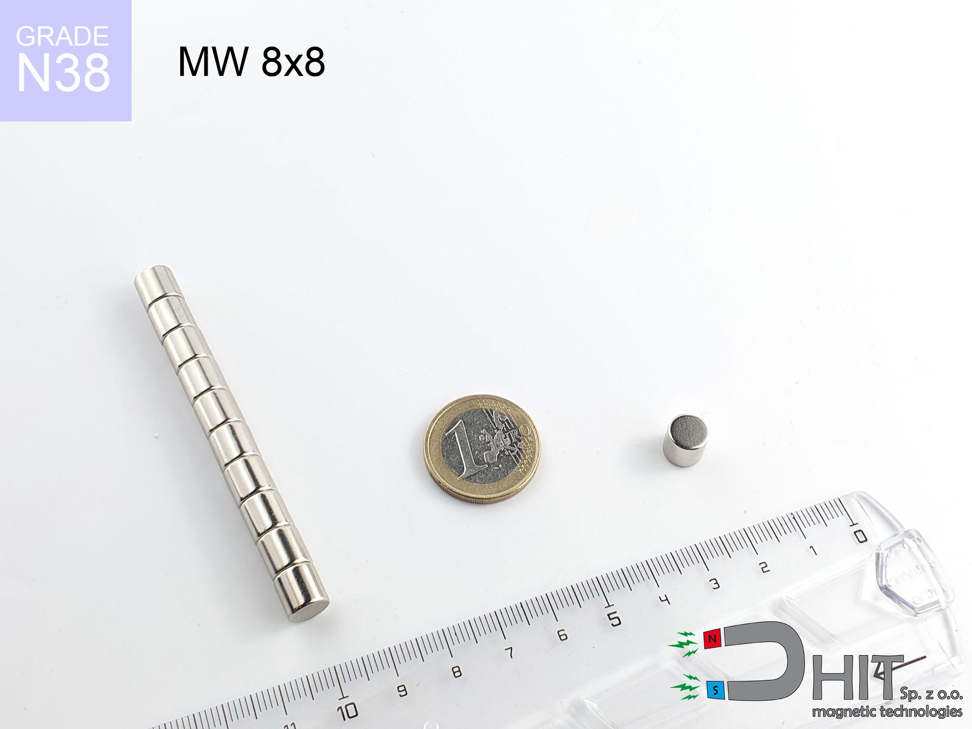
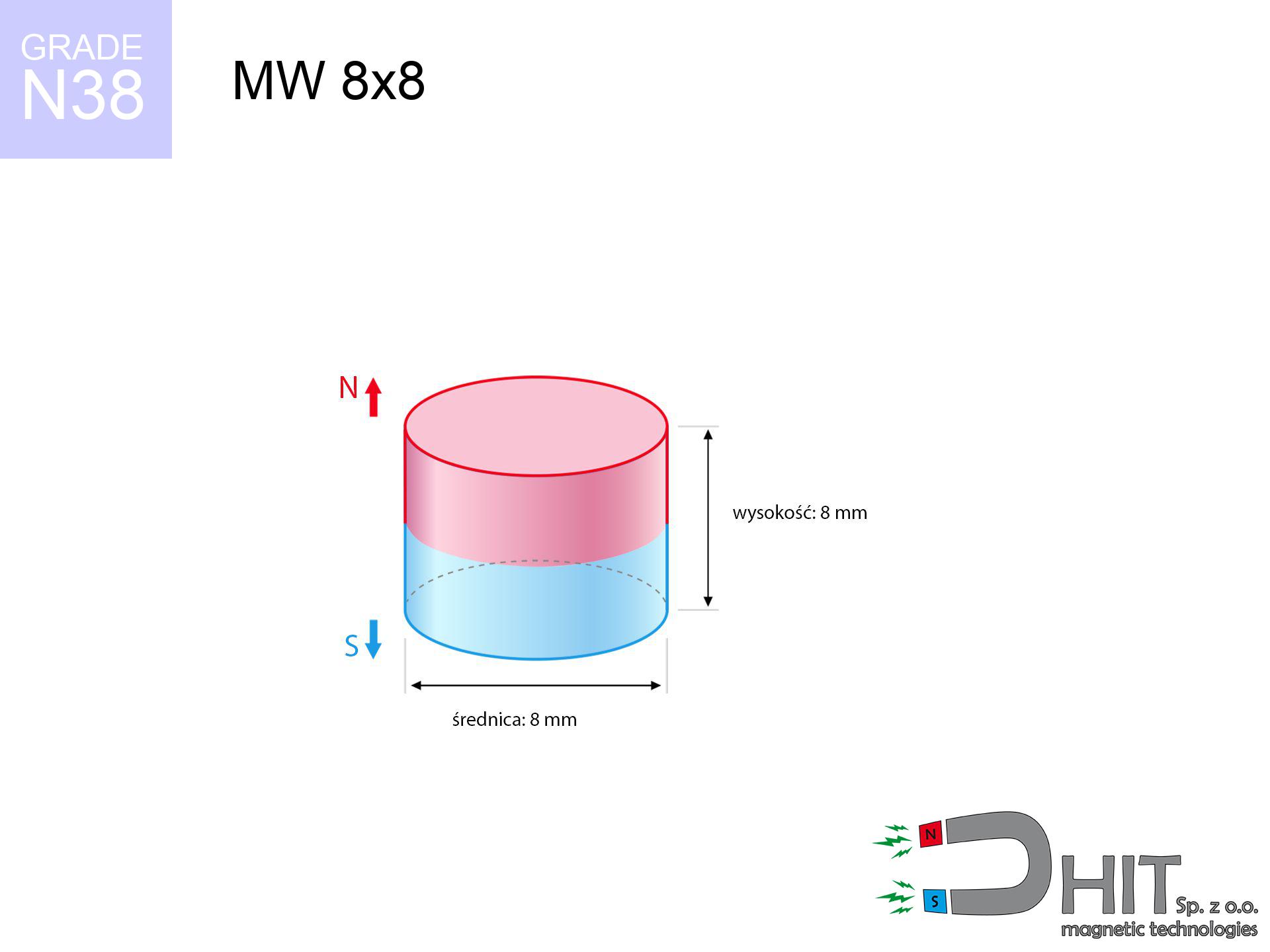
MW 8x8 / N38 - cylindrical magnet
cylindrical magnet
Catalog no 010106
GTIN/EAN: 5906301811053
Diameter Ø
8 mm [±0,1 mm]
Height
8 mm [±0,1 mm]
Weight
3.02 g
Magnetization Direction
↑ axial
Load capacity
2.03 kg / 19.92 N
Magnetic Induction
553.67 mT / 5537 Gs
Coating
[NiCuNi] Nickel
1.341 ZŁ with VAT / pcs + price for transport
1.090 ZŁ net + 23% VAT / pcs
bulk discounts:
Need more?Engineering report for this magnet
Full PDF analysis: pull and shear force, effect of distance, temperature and plate thickness, safety distances and the demagnetization curve.
Contact us by phone
+48 888 99 98 98
or get in touch by means of
our online form
our website.
Weight as well as structure of neodymium magnets can be calculated using our
magnetic calculator.
Orders submitted before 14:00 will be dispatched today!
Technical - MW 8x8 / N38 - cylindrical magnet
Specification / characteristics - MW 8x8 / N38 - cylindrical magnet
| properties | values |
|---|---|
| Cat. no. | 010106 |
| GTIN/EAN | 5906301811053 |
| Production/Distribution | Dhit sp. z o.o. |
| Country of origin | Poland / China / Germany |
| Customs code | 85059029 |
| Diameter Ø | 8 mm [±0,1 mm] |
| Height | 8 mm [±0,1 mm] |
| Weight | 3.02 g |
| Magnetization Direction | ↑ axial |
| Load capacity ~ ? | 2.03 kg / 19.92 N |
| Magnetic Induction ~ ? | 553.67 mT / 5537 Gs |
| Coating | [NiCuNi] Nickel |
| Manufacturing Tolerance | ±0.1 mm |
Magnetic properties of material N38
| properties | values | units |
|---|---|---|
| remenance Br [min. - max.] ? | 12.2-12.6 | kGs |
| remenance Br [min. - max.] ? | 1220-1260 | mT |
| coercivity bHc ? | 10.8-11.5 | kOe |
| coercivity bHc ? | 860-915 | kA/m |
| actual internal force iHc | ≥ 12 | kOe |
| actual internal force iHc | ≥ 955 | kA/m |
| energy density [min. - max.] ? | 36-38 | BH max MGOe |
| energy density [min. - max.] ? | 287-303 | BH max KJ/m |
| max. temperature ? | ≤ 80 | °C |
Physical properties of sintered neodymium magnets Nd2Fe14B at 20°C
| properties | values | units |
|---|---|---|
| Vickers hardness | ≥550 | Hv |
| Density | ≥7.4 | g/cm3 |
| Curie Temperature TC | 312 - 380 | °C |
| Curie Temperature TF | 593 - 716 | °F |
| Specific resistance | 150 | μΩ⋅cm |
| Bending strength | 250 | MPa |
| Compressive strength | 1000~1100 | MPa |
| Thermal expansion parallel (∥) to orientation (M) | (3-4) x 10-6 | °C-1 |
| Thermal expansion perpendicular (⊥) to orientation (M) | -(1-3) x 10-6 | °C-1 |
| Young's modulus | 1.7 x 10⁴ | kg/mm² |
Engineering analysis of the magnet - technical parameters
These values represent the result of a mathematical simulation. Results were calculated on models for the class Nd2Fe14B. Actual parameters may differ from theoretical values. Use these data as a preliminary roadmap during assembly planning.
Table 1: Static force (force vs distance) - power drop
MW 8x8 / N38
| Distance (mm) | Induction (Gauss) / mT | Pull Force (kg/lbs/g/N) | Risk Status |
|---|---|---|---|
| 0 mm |
5531 Gs
553.1 mT
|
2.03 kg / 4.48 pounds
2030.0 g / 19.9 N
|
warning |
| 1 mm |
4162 Gs
416.2 mT
|
1.15 kg / 2.53 pounds
1149.3 g / 11.3 N
|
weak grip |
| 2 mm |
2984 Gs
298.4 mT
|
0.59 kg / 1.30 pounds
590.7 g / 5.8 N
|
weak grip |
| 3 mm |
2107 Gs
210.7 mT
|
0.29 kg / 0.65 pounds
294.5 g / 2.9 N
|
weak grip |
| 5 mm |
1084 Gs
108.4 mT
|
0.08 kg / 0.17 pounds
78.0 g / 0.8 N
|
weak grip |
| 10 mm |
296 Gs
29.6 mT
|
0.01 kg / 0.01 pounds
5.8 g / 0.1 N
|
weak grip |
| 15 mm |
118 Gs
11.8 mT
|
0.00 kg / 0.00 pounds
0.9 g / 0.0 N
|
weak grip |
| 20 mm |
58 Gs
5.8 mT
|
0.00 kg / 0.00 pounds
0.2 g / 0.0 N
|
weak grip |
| 30 mm |
20 Gs
2.0 mT
|
0.00 kg / 0.00 pounds
0.0 g / 0.0 N
|
weak grip |
| 50 mm |
5 Gs
0.5 mT
|
0.00 kg / 0.00 pounds
0.0 g / 0.0 N
|
weak grip |
Table 2: Sliding load (wall)
MW 8x8 / N38
| Distance (mm) | Friction coefficient | Pull Force (kg/lbs/g/N) |
|---|---|---|
| 0 mm | Stal (~0.2) |
0.41 kg / 0.90 pounds
406.0 g / 4.0 N
|
| 1 mm | Stal (~0.2) |
0.23 kg / 0.51 pounds
230.0 g / 2.3 N
|
| 2 mm | Stal (~0.2) |
0.12 kg / 0.26 pounds
118.0 g / 1.2 N
|
| 3 mm | Stal (~0.2) |
0.06 kg / 0.13 pounds
58.0 g / 0.6 N
|
| 5 mm | Stal (~0.2) |
0.02 kg / 0.04 pounds
16.0 g / 0.2 N
|
| 10 mm | Stal (~0.2) |
0.00 kg / 0.00 pounds
2.0 g / 0.0 N
|
| 15 mm | Stal (~0.2) |
0.00 kg / 0.00 pounds
0.0 g / 0.0 N
|
| 20 mm | Stal (~0.2) |
0.00 kg / 0.00 pounds
0.0 g / 0.0 N
|
| 30 mm | Stal (~0.2) |
0.00 kg / 0.00 pounds
0.0 g / 0.0 N
|
| 50 mm | Stal (~0.2) |
0.00 kg / 0.00 pounds
0.0 g / 0.0 N
|
Table 3: Vertical assembly (sliding) - behavior on slippery surfaces
MW 8x8 / N38
| Surface type | Friction coefficient / % Mocy | Max load (kg/lbs/g/N) |
|---|---|---|
| Raw steel |
µ = 0.3
30% Nominalnej Siły
|
0.61 kg / 1.34 pounds
609.0 g / 6.0 N
|
| Painted steel (standard) |
µ = 0.2
20% Nominalnej Siły
|
0.41 kg / 0.90 pounds
406.0 g / 4.0 N
|
| Oily/slippery steel |
µ = 0.1
10% Nominalnej Siły
|
0.20 kg / 0.45 pounds
203.0 g / 2.0 N
|
| Magnet with anti-slip rubber |
µ = 0.5
50% Nominalnej Siły
|
1.02 kg / 2.24 pounds
1015.0 g / 10.0 N
|
Table 4: Steel thickness (saturation) - sheet metal selection
MW 8x8 / N38
| Steel thickness (mm) | % power | Real pull force (kg/lbs/g/N) |
|---|---|---|
| 0.5 mm |
|
0.20 kg / 0.45 pounds
203.0 g / 2.0 N
|
| 1 mm |
|
0.51 kg / 1.12 pounds
507.5 g / 5.0 N
|
| 2 mm |
|
1.02 kg / 2.24 pounds
1015.0 g / 10.0 N
|
| 3 mm |
|
1.52 kg / 3.36 pounds
1522.5 g / 14.9 N
|
| 5 mm |
|
2.03 kg / 4.48 pounds
2030.0 g / 19.9 N
|
| 10 mm |
|
2.03 kg / 4.48 pounds
2030.0 g / 19.9 N
|
| 11 mm |
|
2.03 kg / 4.48 pounds
2030.0 g / 19.9 N
|
| 12 mm |
|
2.03 kg / 4.48 pounds
2030.0 g / 19.9 N
|
Table 5: Thermal resistance (stability) - power drop
MW 8x8 / N38
| Ambient temp. (°C) | Power loss | Remaining pull (kg/lbs/g/N) | Status |
|---|---|---|---|
| 20 °C | 0.0% |
2.03 kg / 4.48 pounds
2030.0 g / 19.9 N
|
OK |
| 40 °C | -2.2% |
1.99 kg / 4.38 pounds
1985.3 g / 19.5 N
|
OK |
| 60 °C | -4.4% |
1.94 kg / 4.28 pounds
1940.7 g / 19.0 N
|
OK |
| 80 °C | -6.6% |
1.90 kg / 4.18 pounds
1896.0 g / 18.6 N
|
|
| 100 °C | -28.8% |
1.45 kg / 3.19 pounds
1445.4 g / 14.2 N
|
Table 6: Magnet-Magnet interaction (attraction) - forces in the system
MW 8x8 / N38
| Gap (mm) | Attraction (kg/lbs) (N-S) | Shear Force (kg/lbs/g/N) | Repulsion (kg/lbs) (N-N) |
|---|---|---|---|
| 0 mm |
9.48 kg / 20.90 pounds
6 000 Gs
|
1.42 kg / 3.14 pounds
1422 g / 14.0 N
|
N/A |
| 1 mm |
7.26 kg / 16.01 pounds
9 682 Gs
|
1.09 kg / 2.40 pounds
1089 g / 10.7 N
|
6.54 kg / 14.41 pounds
~0 Gs
|
| 2 mm |
5.37 kg / 11.83 pounds
8 324 Gs
|
0.81 kg / 1.78 pounds
805 g / 7.9 N
|
4.83 kg / 10.65 pounds
~0 Gs
|
| 3 mm |
3.88 kg / 8.55 pounds
7 074 Gs
|
0.58 kg / 1.28 pounds
582 g / 5.7 N
|
3.49 kg / 7.69 pounds
~0 Gs
|
| 5 mm |
1.95 kg / 4.30 pounds
5 016 Gs
|
0.29 kg / 0.64 pounds
292 g / 2.9 N
|
1.75 kg / 3.87 pounds
~0 Gs
|
| 10 mm |
0.36 kg / 0.80 pounds
2 169 Gs
|
0.05 kg / 0.12 pounds
55 g / 0.5 N
|
0.33 kg / 0.72 pounds
~0 Gs
|
| 20 mm |
0.03 kg / 0.06 pounds
592 Gs
|
0.00 kg / 0.01 pounds
4 g / 0.0 N
|
0.02 kg / 0.05 pounds
~0 Gs
|
| 50 mm |
0.00 kg / 0.00 pounds
66 Gs
|
0.00 kg / 0.00 pounds
0 g / 0.0 N
|
0.00 kg / 0.00 pounds
~0 Gs
|
| 60 mm |
0.00 kg / 0.00 pounds
41 Gs
|
0.00 kg / 0.00 pounds
0 g / 0.0 N
|
0.00 kg / 0.00 pounds
~0 Gs
|
| 70 mm |
0.00 kg / 0.00 pounds
27 Gs
|
0.00 kg / 0.00 pounds
0 g / 0.0 N
|
0.00 kg / 0.00 pounds
~0 Gs
|
| 80 mm |
0.00 kg / 0.00 pounds
19 Gs
|
0.00 kg / 0.00 pounds
0 g / 0.0 N
|
0.00 kg / 0.00 pounds
~0 Gs
|
| 90 mm |
0.00 kg / 0.00 pounds
14 Gs
|
0.00 kg / 0.00 pounds
0 g / 0.0 N
|
0.00 kg / 0.00 pounds
~0 Gs
|
| 100 mm |
0.00 kg / 0.00 pounds
10 Gs
|
0.00 kg / 0.00 pounds
0 g / 0.0 N
|
0.00 kg / 0.00 pounds
~0 Gs
|
Table 7: Safety (HSE) (electronics) - precautionary measures
MW 8x8 / N38
| Object / Device | Limit (Gauss) / mT | Safe distance |
|---|---|---|
| Pacemaker | 5 Gs (0.5 mT) | 5.5 cm |
| Hearing aid | 10 Gs (1.0 mT) | 4.0 cm |
| Mechanical watch | 20 Gs (2.0 mT) | 3.5 cm |
| Phone / Smartphone | 40 Gs (4.0 mT) | 2.5 cm |
| Remote | 50 Gs (5.0 mT) | 2.5 cm |
| Payment card | 400 Gs (40.0 mT) | 1.0 cm |
| HDD hard drive | 600 Gs (60.0 mT) | 1.0 cm |
Table 8: Collisions (kinetic energy) - collision effects
MW 8x8 / N38
| Start from (mm) | Speed (km/h) | Energy (J) | Predicted outcome |
|---|---|---|---|
| 10 mm |
26.19 km/h
(7.28 m/s)
|
0.08 J | |
| 30 mm |
45.29 km/h
(12.58 m/s)
|
0.24 J | |
| 50 mm |
58.47 km/h
(16.24 m/s)
|
0.40 J | |
| 100 mm |
82.68 km/h
(22.97 m/s)
|
0.80 J |
Table 9: Surface protection spec
MW 8x8 / N38
| Technical parameter | Value / Description |
|---|---|
| Coating type | [NiCuNi] Nickel |
| Layer structure | Nickel - Copper - Nickel |
| Layer thickness | 10-20 µm |
| Salt spray test (SST) ? | 24 h |
| Recommended environment | Indoors only (dry) |
Table 10: Construction data (Flux)
MW 8x8 / N38
| Parameter | Value | SI Unit / Description |
|---|---|---|
| Magnetic Flux | 2 868 Mx | 28.7 µWb |
| Pc Coefficient | 0.89 | High (Stable) |
Table 11: Submerged application
MW 8x8 / N38
| Environment | Effective steel pull | Effect |
|---|---|---|
| Air (land) | 2.03 kg | Standard |
| Water (riverbed) |
2.32 kg
(+0.29 kg buoyancy gain)
|
+14.5% |
1. Sliding resistance
*Warning: On a vertical wall, the magnet holds merely approx. 20-30% of its nominal pull.
2. Efficiency vs thickness
*Thin steel (e.g. computer case) significantly limits the holding force.
3. Heat tolerance
*For N38 grade, the critical limit is 80°C.
4. Demagnetization curve and operating point (B-H)
chart generated for the permeance coefficient Pc (Permeance Coefficient) = 0.89
This simulation demonstrates the magnetic stability of the selected magnet under specific geometric conditions. The solid red line represents the demagnetization curve (material potential), while the dashed blue line is the load line based on the magnet's geometry. The Pc (Permeance Coefficient), also known as the load line slope, is a dimensionless value that describes the relationship between the magnet's shape and its magnetic stability. The intersection of these two lines (the black dot) is the operating point — it determines the actual magnetic flux density generated by the magnet in this specific configuration. A higher Pc value means the magnet is more 'slender' (tall relative to its area), resulting in a higher operating point and better resistance to irreversible demagnetization caused by external fields or temperature. A value of 0.42 is relatively low (typical for flat magnets), meaning the operating point is closer to the 'knee' of the curve — caution is advised when operating at temperatures near the maximum limit to avoid strength loss.
Material specification
| iron (Fe) | 64% – 68% |
| neodymium (Nd) | 29% – 32% |
| boron (B) | 1.1% – 1.2% |
| dysprosium (Dy) | 0.5% – 2.0% |
| coating (Ni-Cu-Ni) | < 0.05% |
Sustainability
| recyclability (EoL) | 100% |
| recycled raw materials | ~10% (pre-cons) |
| carbon footprint | low / zredukowany |
| waste code (EWC) | 16 02 16 |
Other deals

![UMGGZ 22x6 [M4] GZ / N38 - rubber magnetic holder external thread](https://cdn3.dhit.pl/graphics/products/umg-22x6-m4-gz-hiw.jpg "UMGGZ 22x6 [M4] GZ / N38 - rubber magnetic holder external thread")

![SM 25x400 [2xM8] / N52 - magnetic separator](https://cdn3.dhit.pl/graphics/products/sm-25x400-2xm8-hoj.jpg "SM 25x400 [2xM8] / N52 - magnetic separator")
Advantages as well as disadvantages of neodymium magnets.
Strengths
- They have stable power, and over nearly ten years their attraction force decreases symbolically – ~1% (in testing),
- They are extremely resistant to demagnetization induced by external magnetic fields,
- A magnet with a shiny gold surface is more attractive,
- Magnetic induction on the working part of the magnet is maximum,
- Due to their durability and thermal resistance, neodymium magnets are capable of operate (depending on the shape) even at high temperatures reaching 230°C or more...
- Considering the option of free forming and adaptation to specialized requirements, magnetic components can be created in a broad palette of geometric configurations, which makes them more universal,
- Wide application in innovative solutions – they are commonly used in computer drives, drive modules, medical devices, also modern systems.
- Thanks to efficiency per cm³, small magnets offer high operating force, occupying minimum space,
Weaknesses
- Brittleness is one of their disadvantages. Upon intense impact they can break. We advise keeping them in a special holder, which not only secures them against impacts but also increases their durability
- Neodymium magnets demagnetize when exposed to high temperatures. After reaching 80°C, many of them experience permanent weakening of strength (a factor is the shape as well as dimensions of the magnet). We offer magnets specially adapted to work at temperatures up to 230°C marked [AH], which are extremely resistant to heat
- Magnets exposed to a humid environment can corrode. Therefore while using outdoors, we recommend using water-impermeable magnets made of rubber, plastic or other material protecting against moisture
- We suggest a housing - magnetic mechanism, due to difficulties in producing threads inside the magnet and complex shapes.
- Health risk resulting from small fragments of magnets pose a threat, in case of ingestion, which becomes key in the context of child health protection. Additionally, small elements of these magnets are able to be problematic in diagnostics medical in case of swallowing.
- High unit price – neodymium magnets have a higher price than other types of magnets (e.g. ferrite), which can limit application in large quantities
Lifting parameters
Best holding force of the magnet in ideal parameters – what it depends on?
- with the contact of a sheet made of special test steel, guaranteeing maximum field concentration
- possessing a massiveness of min. 10 mm to ensure full flux closure
- with a plane free of scratches
- without the slightest insulating layer between the magnet and steel
- during pulling in a direction vertical to the mounting surface
- at temperature approx. 20 degrees Celsius
Magnet lifting force in use – key factors
- Space between surfaces – even a fraction of a millimeter of separation (caused e.g. by varnish or unevenness) diminishes the pulling force, often by half at just 0.5 mm.
- Pull-off angle – note that the magnet holds strongest perpendicularly. Under sliding down, the holding force drops significantly, often to levels of 20-30% of the maximum value.
- Plate thickness – too thin sheet causes magnetic saturation, causing part of the flux to be lost to the other side.
- Steel grade – ideal substrate is high-permeability steel. Cast iron may have worse magnetic properties.
- Base smoothness – the smoother and more polished the plate, the better the adhesion and higher the lifting capacity. Roughness creates an air distance.
- Temperature influence – hot environment weakens pulling force. Exceeding the limit temperature can permanently demagnetize the magnet.
Holding force was measured on the plate surface of 20 mm thickness, when a perpendicular force was applied, whereas under shearing force the lifting capacity is smaller. Moreover, even a slight gap between the magnet’s surface and the plate decreases the holding force.
Safe handling of neodymium magnets
Warning for heart patients
People with a pacemaker have to maintain an absolute distance from magnets. The magnetic field can disrupt the operation of the implant.
Nickel coating and allergies
Some people suffer from a contact allergy to Ni, which is the typical protective layer for NdFeB magnets. Prolonged contact may cause an allergic reaction. We strongly advise use protective gloves.
Precision electronics
Be aware: neodymium magnets generate a field that interferes with precision electronics. Maintain a separation from your phone, tablet, and GPS.
Serious injuries
Pinching hazard: The attraction force is so great that it can cause hematomas, crushing, and even bone fractures. Use thick gloves.
Material brittleness
Neodymium magnets are sintered ceramics, meaning they are fragile like glass. Impact of two magnets leads to them breaking into shards.
Power loss in heat
Watch the temperature. Heating the magnet above 80 degrees Celsius will ruin its properties and strength.
Safe operation
Use magnets consciously. Their powerful strength can surprise even professionals. Stay alert and do not underestimate their force.
Cards and drives
Data protection: Strong magnets can damage data carriers and sensitive devices (pacemakers, medical aids, mechanical watches).
Dust is flammable
Machining of neodymium magnets poses a fire hazard. Neodymium dust oxidizes rapidly with oxygen and is hard to extinguish.
Danger to the youngest
NdFeB magnets are not suitable for play. Swallowing a few magnets can lead to them pinching intestinal walls, which poses a critical condition and necessitates urgent medical intervention.
Tabela kosztu i czasu dostawy
Płatność przed wysyłką:

GLS kurier
Przesyłka będzie u Ciebie za 2-3 dni
14.99 ZŁ

InPost Paczkomaty 24/7
Przesyłka będzie u Ciebie za 1-2 dni
12.30 ZŁ
Płatność przy odbiorze (pobranie):
GLS kurier
Przesyłka będzie u Ciebie za 1-2 dni
23.00 ZŁ
Rate the product
Your rating