
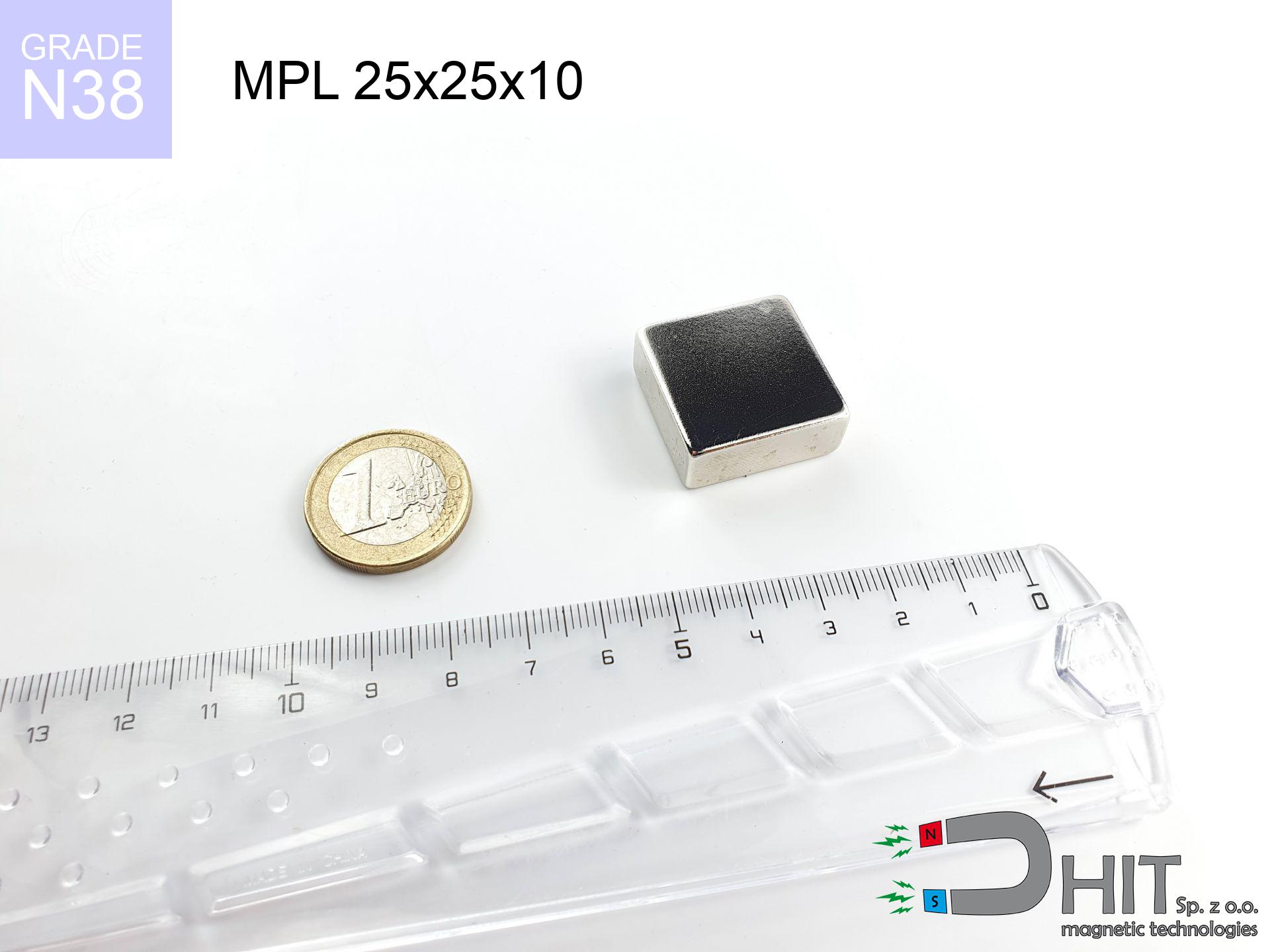
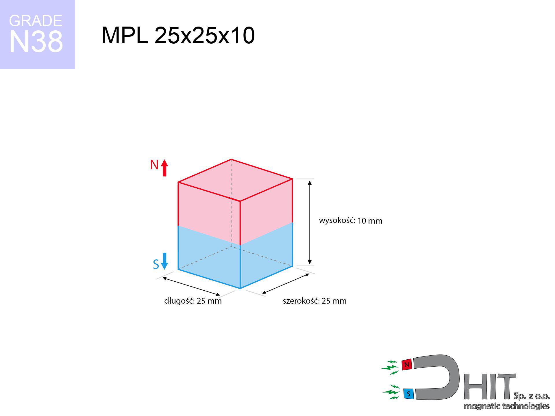
MPL 25x25x10 / N38 - lamellar magnet
lamellar magnet
Catalog no 020137
GTIN/EAN: 5906301811435
length
25 mm [±0,1 mm]
Width
25 mm [±0,1 mm]
Height
10 mm [±0,1 mm]
Weight
46.88 g
Magnetization Direction
↑ axial
Load capacity
19.39 kg / 190.25 N
Magnetic Induction
361.04 mT / 3610 Gs
Coating
[NiCuNi] Nickel
20.29 ZŁ with VAT / pcs + price for transport
16.50 ZŁ net + 23% VAT / pcs
bulk discounts:
Need more?
Call us now
+48 22 499 98 98
otherwise contact us by means of
form
our website.
Force as well as structure of a magnet can be reviewed on our
magnetic calculator.
Order by 14:00 and we’ll ship today!
Technical of the product - MPL 25x25x10 / N38 - lamellar magnet
Specification / characteristics - MPL 25x25x10 / N38 - lamellar magnet
| properties | values |
|---|---|
| Cat. no. | 020137 |
| GTIN/EAN | 5906301811435 |
| Production/Distribution | Dhit sp. z o.o. |
| Country of origin | Poland / China / Germany |
| Customs code | 85059029 |
| length | 25 mm [±0,1 mm] |
| Width | 25 mm [±0,1 mm] |
| Height | 10 mm [±0,1 mm] |
| Weight | 46.88 g |
| Magnetization Direction | ↑ axial |
| Load capacity ~ ? | 19.39 kg / 190.25 N |
| Magnetic Induction ~ ? | 361.04 mT / 3610 Gs |
| Coating | [NiCuNi] Nickel |
| Manufacturing Tolerance | ±0.1 mm |
Magnetic properties of material N38
| properties | values | units |
|---|---|---|
| remenance Br [min. - max.] ? | 12.2-12.6 | kGs |
| remenance Br [min. - max.] ? | 1220-1260 | mT |
| coercivity bHc ? | 10.8-11.5 | kOe |
| coercivity bHc ? | 860-915 | kA/m |
| actual internal force iHc | ≥ 12 | kOe |
| actual internal force iHc | ≥ 955 | kA/m |
| energy density [min. - max.] ? | 36-38 | BH max MGOe |
| energy density [min. - max.] ? | 287-303 | BH max KJ/m |
| max. temperature ? | ≤ 80 | °C |
Physical properties of sintered neodymium magnets Nd2Fe14B at 20°C
| properties | values | units |
|---|---|---|
| Vickers hardness | ≥550 | Hv |
| Density | ≥7.4 | g/cm3 |
| Curie Temperature TC | 312 - 380 | °C |
| Curie Temperature TF | 593 - 716 | °F |
| Specific resistance | 150 | μΩ⋅cm |
| Bending strength | 250 | MPa |
| Compressive strength | 1000~1100 | MPa |
| Thermal expansion parallel (∥) to orientation (M) | (3-4) x 10-6 | °C-1 |
| Thermal expansion perpendicular (⊥) to orientation (M) | -(1-3) x 10-6 | °C-1 |
| Young's modulus | 1.7 x 10⁴ | kg/mm² |
Physical modeling of the product - technical parameters
The following data represent the outcome of a physical calculation. Values rely on models for the class Nd2Fe14B. Actual performance may differ from theoretical values. Please consider these data as a supplementary guide for designers.
Table 1: Static force (pull vs distance) - power drop
MPL 25x25x10 / N38
| Distance (mm) | Induction (Gauss) / mT | Pull Force (kg/lbs/g/N) | Risk Status |
|---|---|---|---|
| 0 mm |
3610 Gs
361.0 mT
|
19.39 kg / 42.75 lbs
19390.0 g / 190.2 N
|
dangerous! |
| 1 mm |
3392 Gs
339.2 mT
|
17.12 kg / 37.74 lbs
17117.7 g / 167.9 N
|
dangerous! |
| 2 mm |
3156 Gs
315.6 mT
|
14.82 kg / 32.68 lbs
14822.5 g / 145.4 N
|
dangerous! |
| 3 mm |
2913 Gs
291.3 mT
|
12.63 kg / 27.85 lbs
12631.8 g / 123.9 N
|
dangerous! |
| 5 mm |
2436 Gs
243.6 mT
|
8.83 kg / 19.46 lbs
8827.9 g / 86.6 N
|
medium risk |
| 10 mm |
1464 Gs
146.4 mT
|
3.19 kg / 7.04 lbs
3191.5 g / 31.3 N
|
medium risk |
| 15 mm |
872 Gs
87.2 mT
|
1.13 kg / 2.49 lbs
1131.5 g / 11.1 N
|
safe |
| 20 mm |
538 Gs
53.8 mT
|
0.43 kg / 0.95 lbs
430.4 g / 4.2 N
|
safe |
| 30 mm |
234 Gs
23.4 mT
|
0.08 kg / 0.18 lbs
81.8 g / 0.8 N
|
safe |
| 50 mm |
68 Gs
6.8 mT
|
0.01 kg / 0.02 lbs
6.9 g / 0.1 N
|
safe |
Table 2: Vertical capacity (wall)
MPL 25x25x10 / N38
| Distance (mm) | Friction coefficient | Pull Force (kg/lbs/g/N) |
|---|---|---|
| 0 mm | Stal (~0.2) |
3.88 kg / 8.55 lbs
3878.0 g / 38.0 N
|
| 1 mm | Stal (~0.2) |
3.42 kg / 7.55 lbs
3424.0 g / 33.6 N
|
| 2 mm | Stal (~0.2) |
2.96 kg / 6.53 lbs
2964.0 g / 29.1 N
|
| 3 mm | Stal (~0.2) |
2.53 kg / 5.57 lbs
2526.0 g / 24.8 N
|
| 5 mm | Stal (~0.2) |
1.77 kg / 3.89 lbs
1766.0 g / 17.3 N
|
| 10 mm | Stal (~0.2) |
0.64 kg / 1.41 lbs
638.0 g / 6.3 N
|
| 15 mm | Stal (~0.2) |
0.23 kg / 0.50 lbs
226.0 g / 2.2 N
|
| 20 mm | Stal (~0.2) |
0.09 kg / 0.19 lbs
86.0 g / 0.8 N
|
| 30 mm | Stal (~0.2) |
0.02 kg / 0.04 lbs
16.0 g / 0.2 N
|
| 50 mm | Stal (~0.2) |
0.00 kg / 0.00 lbs
2.0 g / 0.0 N
|
Table 3: Vertical assembly (shearing) - behavior on slippery surfaces
MPL 25x25x10 / N38
| Surface type | Friction coefficient / % Mocy | Max load (kg/lbs/g/N) |
|---|---|---|
| Raw steel |
µ = 0.3
30% Nominalnej Siły
|
5.82 kg / 12.82 lbs
5817.0 g / 57.1 N
|
| Painted steel (standard) |
µ = 0.2
20% Nominalnej Siły
|
3.88 kg / 8.55 lbs
3878.0 g / 38.0 N
|
| Oily/slippery steel |
µ = 0.1
10% Nominalnej Siły
|
1.94 kg / 4.27 lbs
1939.0 g / 19.0 N
|
| Magnet with anti-slip rubber |
µ = 0.5
50% Nominalnej Siły
|
9.70 kg / 21.37 lbs
9695.0 g / 95.1 N
|
Table 4: Steel thickness (substrate influence) - power losses
MPL 25x25x10 / N38
| Steel thickness (mm) | % power | Real pull force (kg/lbs/g/N) |
|---|---|---|
| 0.5 mm |
|
0.97 kg / 2.14 lbs
969.5 g / 9.5 N
|
| 1 mm |
|
2.42 kg / 5.34 lbs
2423.8 g / 23.8 N
|
| 2 mm |
|
4.85 kg / 10.69 lbs
4847.5 g / 47.6 N
|
| 3 mm |
|
7.27 kg / 16.03 lbs
7271.3 g / 71.3 N
|
| 5 mm |
|
12.12 kg / 26.72 lbs
12118.8 g / 118.9 N
|
| 10 mm |
|
19.39 kg / 42.75 lbs
19390.0 g / 190.2 N
|
| 11 mm |
|
19.39 kg / 42.75 lbs
19390.0 g / 190.2 N
|
| 12 mm |
|
19.39 kg / 42.75 lbs
19390.0 g / 190.2 N
|
Table 5: Thermal resistance (material behavior) - thermal limit
MPL 25x25x10 / N38
| Ambient temp. (°C) | Power loss | Remaining pull (kg/lbs/g/N) | Status |
|---|---|---|---|
| 20 °C | 0.0% |
19.39 kg / 42.75 lbs
19390.0 g / 190.2 N
|
OK |
| 40 °C | -2.2% |
18.96 kg / 41.81 lbs
18963.4 g / 186.0 N
|
OK |
| 60 °C | -4.4% |
18.54 kg / 40.87 lbs
18536.8 g / 181.8 N
|
|
| 80 °C | -6.6% |
18.11 kg / 39.93 lbs
18110.3 g / 177.7 N
|
|
| 100 °C | -28.8% |
13.81 kg / 30.44 lbs
13805.7 g / 135.4 N
|
Table 6: Magnet-Magnet interaction (attraction) - field range
MPL 25x25x10 / N38
| Gap (mm) | Attraction (kg/lbs) (N-S) | Sliding Force (kg/lbs/g/N) | Repulsion (kg/lbs) (N-N) |
|---|---|---|---|
| 0 mm |
50.20 kg / 110.68 lbs
5 073 Gs
|
7.53 kg / 16.60 lbs
7531 g / 73.9 N
|
N/A |
| 1 mm |
47.31 kg / 104.30 lbs
7 008 Gs
|
7.10 kg / 15.65 lbs
7097 g / 69.6 N
|
42.58 kg / 93.87 lbs
~0 Gs
|
| 2 mm |
44.32 kg / 97.71 lbs
6 783 Gs
|
6.65 kg / 14.66 lbs
6648 g / 65.2 N
|
39.89 kg / 87.94 lbs
~0 Gs
|
| 3 mm |
41.33 kg / 91.12 lbs
6 550 Gs
|
6.20 kg / 13.67 lbs
6200 g / 60.8 N
|
37.20 kg / 82.01 lbs
~0 Gs
|
| 5 mm |
35.49 kg / 78.25 lbs
6 070 Gs
|
5.32 kg / 11.74 lbs
5324 g / 52.2 N
|
31.94 kg / 70.43 lbs
~0 Gs
|
| 10 mm |
22.86 kg / 50.39 lbs
4 871 Gs
|
3.43 kg / 7.56 lbs
3429 g / 33.6 N
|
20.57 kg / 45.35 lbs
~0 Gs
|
| 20 mm |
8.26 kg / 18.22 lbs
2 929 Gs
|
1.24 kg / 2.73 lbs
1240 g / 12.2 N
|
7.44 kg / 16.40 lbs
~0 Gs
|
| 50 mm |
0.46 kg / 1.02 lbs
695 Gs
|
0.07 kg / 0.15 lbs
70 g / 0.7 N
|
0.42 kg / 0.92 lbs
~0 Gs
|
| 60 mm |
0.21 kg / 0.47 lbs
469 Gs
|
0.03 kg / 0.07 lbs
32 g / 0.3 N
|
0.19 kg / 0.42 lbs
~0 Gs
|
| 70 mm |
0.10 kg / 0.23 lbs
329 Gs
|
0.02 kg / 0.03 lbs
16 g / 0.2 N
|
0.09 kg / 0.21 lbs
~0 Gs
|
| 80 mm |
0.05 kg / 0.12 lbs
239 Gs
|
0.01 kg / 0.02 lbs
8 g / 0.1 N
|
0.05 kg / 0.11 lbs
~0 Gs
|
| 90 mm |
0.03 kg / 0.07 lbs
178 Gs
|
0.00 kg / 0.01 lbs
5 g / 0.0 N
|
0.03 kg / 0.06 lbs
~0 Gs
|
| 100 mm |
0.02 kg / 0.04 lbs
136 Gs
|
0.00 kg / 0.01 lbs
3 g / 0.0 N
|
0.02 kg / 0.04 lbs
~0 Gs
|
Table 7: Hazards (implants) - warnings
MPL 25x25x10 / N38
| Object / Device | Limit (Gauss) / mT | Safe distance |
|---|---|---|
| Pacemaker | 5 Gs (0.5 mT) | 13.0 cm |
| Hearing aid | 10 Gs (1.0 mT) | 10.5 cm |
| Mechanical watch | 20 Gs (2.0 mT) | 8.0 cm |
| Phone / Smartphone | 40 Gs (4.0 mT) | 6.5 cm |
| Remote | 50 Gs (5.0 mT) | 6.0 cm |
| Payment card | 400 Gs (40.0 mT) | 2.5 cm |
| HDD hard drive | 600 Gs (60.0 mT) | 2.0 cm |
Table 8: Dynamics (cracking risk) - collision effects
MPL 25x25x10 / N38
| Start from (mm) | Speed (km/h) | Energy (J) | Predicted outcome |
|---|---|---|---|
| 10 mm |
22.52 km/h
(6.26 m/s)
|
0.92 J | |
| 30 mm |
35.62 km/h
(9.89 m/s)
|
2.29 J | |
| 50 mm |
45.87 km/h
(12.74 m/s)
|
3.81 J | |
| 100 mm |
64.86 km/h
(18.02 m/s)
|
7.61 J |
Table 9: Coating parameters (durability)
MPL 25x25x10 / N38
| Technical parameter | Value / Description |
|---|---|
| Coating type | [NiCuNi] Nickel |
| Layer structure | Nickel - Copper - Nickel |
| Layer thickness | 10-20 µm |
| Salt spray test (SST) ? | 24 h |
| Recommended environment | Indoors only (dry) |
Table 10: Construction data (Flux)
MPL 25x25x10 / N38
| Parameter | Value | SI Unit / Description |
|---|---|---|
| Magnetic Flux | 23 497 Mx | 235.0 µWb |
| Pc Coefficient | 0.46 | Low (Flat) |
Table 11: Submerged application
MPL 25x25x10 / N38
| Environment | Effective steel pull | Effect |
|---|---|---|
| Air (land) | 19.39 kg | Standard |
| Water (riverbed) |
22.20 kg
(+2.81 kg buoyancy gain)
|
+14.5% |
1. Wall mount (shear)
*Caution: On a vertical wall, the magnet retains only ~20% of its nominal pull.
2. Efficiency vs thickness
*Thin steel (e.g. computer case) significantly weakens the holding force.
3. Power loss vs temp
*For N38 grade, the critical limit is 80°C.
4. Demagnetization curve and operating point (B-H)
chart generated for the permeance coefficient Pc (Permeance Coefficient) = 0.46
The chart above illustrates the magnetic characteristics of the material within the second quadrant of the hysteresis loop. The solid red line represents the demagnetization curve (material potential), while the dashed blue line is the load line based on the magnet's geometry. The Pc (Permeance Coefficient), also known as the load line slope, is a dimensionless value that describes the relationship between the magnet's shape and its magnetic stability. The intersection of these two lines (the black dot) is the operating point — it determines the actual magnetic flux density generated by the magnet in this specific configuration. A higher Pc value means the magnet is more 'slender' (tall relative to its area), resulting in a higher operating point and better resistance to irreversible demagnetization caused by external fields or temperature. A value of 0.42 is relatively low (typical for flat magnets), meaning the operating point is closer to the 'knee' of the curve — caution is advised when operating at temperatures near the maximum limit to avoid strength loss.
Chemical composition
| iron (Fe) | 64% – 68% |
| neodymium (Nd) | 29% – 32% |
| boron (B) | 1.1% – 1.2% |
| dysprosium (Dy) | 0.5% – 2.0% |
| coating (Ni-Cu-Ni) | < 0.05% |
Environmental data
| recyclability (EoL) | 100% |
| recycled raw materials | ~10% (pre-cons) |
| carbon footprint | low / zredukowany |
| waste code (EWC) | 16 02 16 |
View also products
![SM 25x200 [2xM8] / N52 - magnetic separator](https://cdn3.dhit.pl/graphics/products/sm-25x200-2xm8-jas.jpg "SM 25x200 [2xM8] / N52 - magnetic separator")


Advantages and disadvantages of rare earth magnets.
Advantages
- They have unchanged lifting capacity, and over more than 10 years their performance decreases symbolically – ~1% (in testing),
- They maintain their magnetic properties even under close interference source,
- By using a smooth coating of gold, the element has an nice look,
- The surface of neodymium magnets generates a intense magnetic field – this is one of their assets,
- Thanks to resistance to high temperature, they are capable of working (depending on the form) even at temperatures up to 230°C and higher...
- In view of the option of accurate shaping and adaptation to custom needs, neodymium magnets can be manufactured in a variety of geometric configurations, which expands the range of possible applications,
- Key role in electronics industry – they are used in mass storage devices, electric motors, diagnostic systems, as well as complex engineering applications.
- Relatively small size with high pulling force – neodymium magnets offer high power in tiny dimensions, which allows their use in small systems
Limitations
- At very strong impacts they can break, therefore we advise placing them in special holders. A metal housing provides additional protection against damage and increases the magnet's durability.
- Neodymium magnets decrease their strength under the influence of heating. As soon as 80°C is exceeded, many of them start losing their force. Therefore, we recommend our special magnets marked [AH], which maintain stability even at temperatures up to 230°C
- Magnets exposed to a humid environment can corrode. Therefore during using outdoors, we recommend using water-impermeable magnets made of rubber, plastic or other material resistant to moisture
- Limited ability of creating nuts in the magnet and complex shapes - preferred is cover - magnet mounting.
- Possible danger related to microscopic parts of magnets are risky, if swallowed, which is particularly important in the context of child health protection. Furthermore, small components of these products are able to be problematic in diagnostics medical when they are in the body.
- Higher cost of purchase is a significant factor to consider compared to ceramic magnets, especially in budget applications
Holding force characteristics
Highest magnetic holding force – what affects it?
- on a plate made of structural steel, effectively closing the magnetic field
- with a thickness no less than 10 mm
- characterized by even structure
- with zero gap (without coatings)
- under perpendicular application of breakaway force (90-degree angle)
- at standard ambient temperature
Practical lifting capacity: influencing factors
- Space between magnet and steel – every millimeter of distance (caused e.g. by veneer or unevenness) drastically reduces the pulling force, often by half at just 0.5 mm.
- Loading method – catalog parameter refers to pulling vertically. When applying parallel force, the magnet holds much less (typically approx. 20-30% of nominal force).
- Substrate thickness – for full efficiency, the steel must be adequately massive. Paper-thin metal restricts the attraction force (the magnet "punches through" it).
- Steel grade – ideal substrate is pure iron steel. Cast iron may attract less.
- Plate texture – smooth surfaces ensure maximum contact, which increases force. Rough surfaces reduce efficiency.
- Thermal environment – heating the magnet causes a temporary drop of induction. It is worth remembering the thermal limit for a given model.
Holding force was checked on a smooth steel plate of 20 mm thickness, when the force acted perpendicularly, however under shearing force the holding force is lower. In addition, even a slight gap between the magnet’s surface and the plate decreases the holding force.
Precautions when working with neodymium magnets
Protect data
Avoid bringing magnets close to a wallet, computer, or TV. The magnetic field can destroy these devices and erase data from cards.
Fire risk
Dust generated during cutting of magnets is combustible. Avoid drilling into magnets unless you are an expert.
Bone fractures
Danger of trauma: The pulling power is so great that it can result in blood blisters, crushing, and even bone fractures. Protective gloves are recommended.
GPS and phone interference
GPS units and mobile phones are highly sensitive to magnetic fields. Direct contact with a powerful NdFeB magnet can decalibrate the sensors in your phone.
Keep away from children
These products are not intended for children. Accidental ingestion of several magnets may result in them pinching intestinal walls, which constitutes a critical condition and necessitates immediate surgery.
Beware of splinters
Neodymium magnets are ceramic materials, meaning they are very brittle. Impact of two magnets leads to them shattering into shards.
Immense force
Before use, check safety instructions. Uncontrolled attraction can break the magnet or hurt your hand. Be predictive.
Skin irritation risks
Allergy Notice: The nickel-copper-nickel coating contains nickel. If an allergic reaction happens, immediately stop handling magnets and use protective gear.
Demagnetization risk
Keep cool. NdFeB magnets are susceptible to heat. If you require operation above 80°C, look for special high-temperature series (H, SH, UH).
Life threat
For implant holders: Powerful magnets disrupt electronics. Maintain at least 30 cm distance or request help to handle the magnets.
Tabela kosztu i czasu dostawy
Płatność przed wysyłką:

GLS kurier
Przesyłka będzie u Ciebie za 2-3 dni
14.99 ZŁ

InPost Paczkomaty 24/7
Przesyłka będzie u Ciebie za 1-2 dni
12.30 ZŁ
Płatność przy odbiorze (pobranie):
GLS kurier
Przesyłka będzie u Ciebie za 1-2 dni
23.00 ZŁ
Rate the product
Your rating