
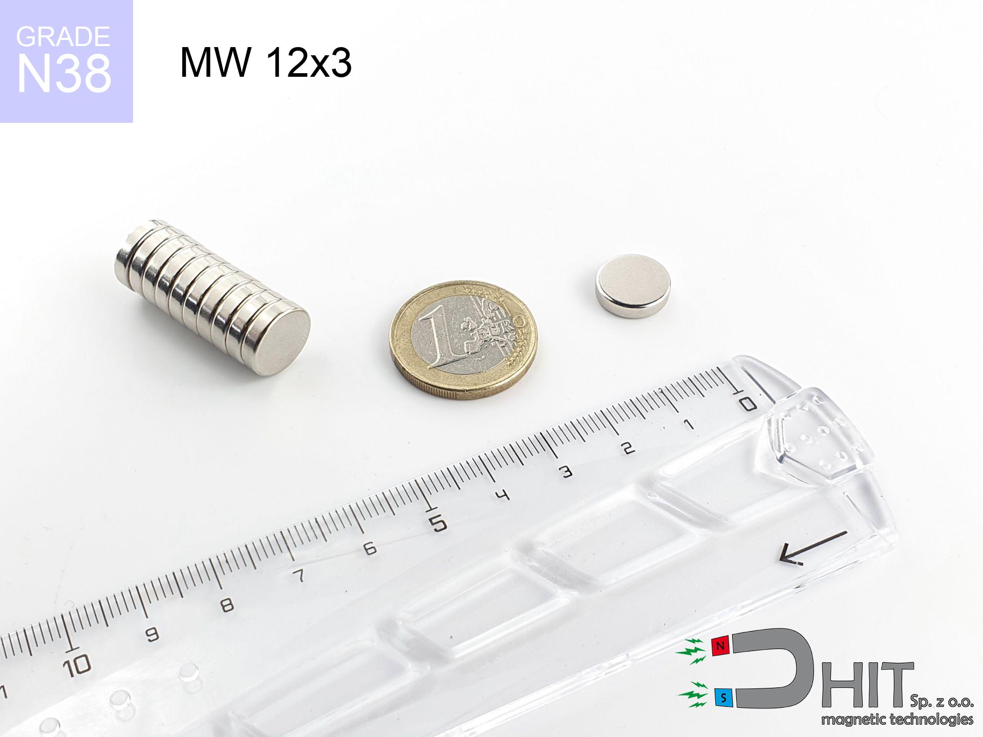
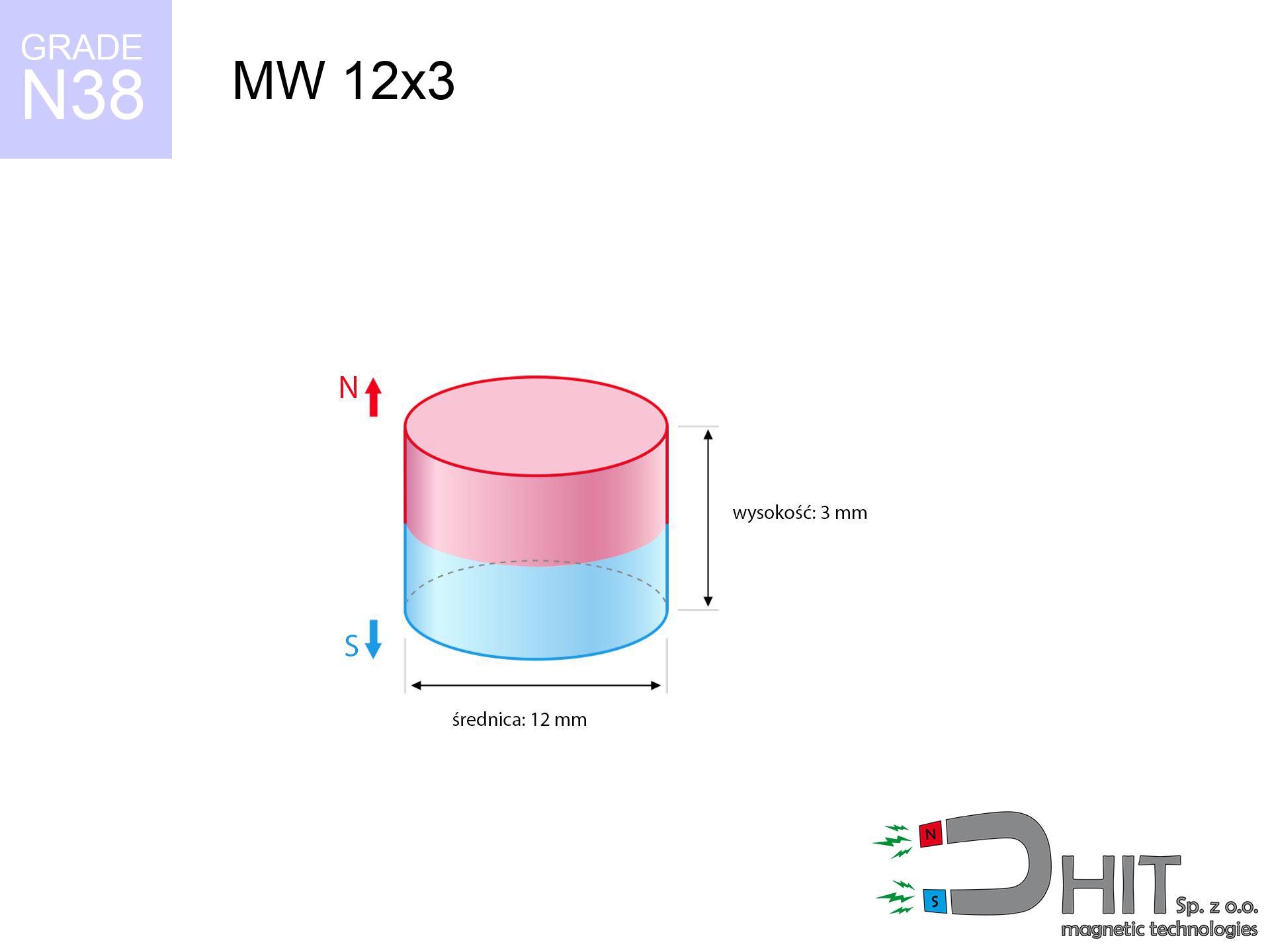
MW 12x3 / N38 - cylindrical magnet
cylindrical magnet
Catalog no 010018
GTIN/EAN: 5906301810179
Diameter Ø
12 mm [±0,1 mm]
Height
3 mm [±0,1 mm]
Weight
2.54 g
Magnetization Direction
↑ axial
Load capacity
2.49 kg / 24.43 N
Magnetic Induction
277.09 mT / 2771 Gs
Coating
[NiCuNi] Nickel
1.648 ZŁ with VAT / pcs + price for transport
1.340 ZŁ net + 23% VAT / pcs
bulk discounts:
Need more?
Call us
+48 22 499 98 98
if you prefer send us a note using
request form
our website.
Specifications along with form of neodymium magnets can be analyzed on our
magnetic mass calculator.
Orders submitted before 14:00 will be dispatched today!
Product card - MW 12x3 / N38 - cylindrical magnet
Specification / characteristics - MW 12x3 / N38 - cylindrical magnet
| properties | values |
|---|---|
| Cat. no. | 010018 |
| GTIN/EAN | 5906301810179 |
| Production/Distribution | Dhit sp. z o.o. |
| Country of origin | Poland / China / Germany |
| Customs code | 85059029 |
| Diameter Ø | 12 mm [±0,1 mm] |
| Height | 3 mm [±0,1 mm] |
| Weight | 2.54 g |
| Magnetization Direction | ↑ axial |
| Load capacity ~ ? | 2.49 kg / 24.43 N |
| Magnetic Induction ~ ? | 277.09 mT / 2771 Gs |
| Coating | [NiCuNi] Nickel |
| Manufacturing Tolerance | ±0.1 mm |
Magnetic properties of material N38
| properties | values | units |
|---|---|---|
| remenance Br [min. - max.] ? | 12.2-12.6 | kGs |
| remenance Br [min. - max.] ? | 1220-1260 | mT |
| coercivity bHc ? | 10.8-11.5 | kOe |
| coercivity bHc ? | 860-915 | kA/m |
| actual internal force iHc | ≥ 12 | kOe |
| actual internal force iHc | ≥ 955 | kA/m |
| energy density [min. - max.] ? | 36-38 | BH max MGOe |
| energy density [min. - max.] ? | 287-303 | BH max KJ/m |
| max. temperature ? | ≤ 80 | °C |
Physical properties of sintered neodymium magnets Nd2Fe14B at 20°C
| properties | values | units |
|---|---|---|
| Vickers hardness | ≥550 | Hv |
| Density | ≥7.4 | g/cm3 |
| Curie Temperature TC | 312 - 380 | °C |
| Curie Temperature TF | 593 - 716 | °F |
| Specific resistance | 150 | μΩ⋅cm |
| Bending strength | 250 | MPa |
| Compressive strength | 1000~1100 | MPa |
| Thermal expansion parallel (∥) to orientation (M) | (3-4) x 10-6 | °C-1 |
| Thermal expansion perpendicular (⊥) to orientation (M) | -(1-3) x 10-6 | °C-1 |
| Young's modulus | 1.7 x 10⁴ | kg/mm² |
Physical modeling of the product - data
The following values are the outcome of a physical analysis. Values are based on models for the material Nd2Fe14B. Actual performance might slightly differ from theoretical values. Use these data as a supplementary guide during assembly planning.
Table 1: Static pull force (pull vs distance) - characteristics
MW 12x3 / N38
| Distance (mm) | Induction (Gauss) / mT | Pull Force (kg/lbs/g/N) | Risk Status |
|---|---|---|---|
| 0 mm |
2770 Gs
277.0 mT
|
2.49 kg / 5.49 LBS
2490.0 g / 24.4 N
|
warning |
| 1 mm |
2420 Gs
242.0 mT
|
1.90 kg / 4.19 LBS
1900.6 g / 18.6 N
|
weak grip |
| 2 mm |
2009 Gs
200.9 mT
|
1.31 kg / 2.89 LBS
1309.4 g / 12.8 N
|
weak grip |
| 3 mm |
1611 Gs
161.1 mT
|
0.84 kg / 1.86 LBS
842.7 g / 8.3 N
|
weak grip |
| 5 mm |
991 Gs
99.1 mT
|
0.32 kg / 0.70 LBS
318.7 g / 3.1 N
|
weak grip |
| 10 mm |
313 Gs
31.3 mT
|
0.03 kg / 0.07 LBS
31.8 g / 0.3 N
|
weak grip |
| 15 mm |
125 Gs
12.5 mT
|
0.01 kg / 0.01 LBS
5.1 g / 0.0 N
|
weak grip |
| 20 mm |
61 Gs
6.1 mT
|
0.00 kg / 0.00 LBS
1.2 g / 0.0 N
|
weak grip |
| 30 mm |
20 Gs
2.0 mT
|
0.00 kg / 0.00 LBS
0.1 g / 0.0 N
|
weak grip |
| 50 mm |
5 Gs
0.5 mT
|
0.00 kg / 0.00 LBS
0.0 g / 0.0 N
|
weak grip |
Table 2: Sliding hold (wall)
MW 12x3 / N38
| Distance (mm) | Friction coefficient | Pull Force (kg/lbs/g/N) |
|---|---|---|
| 0 mm | Stal (~0.2) |
0.50 kg / 1.10 LBS
498.0 g / 4.9 N
|
| 1 mm | Stal (~0.2) |
0.38 kg / 0.84 LBS
380.0 g / 3.7 N
|
| 2 mm | Stal (~0.2) |
0.26 kg / 0.58 LBS
262.0 g / 2.6 N
|
| 3 mm | Stal (~0.2) |
0.17 kg / 0.37 LBS
168.0 g / 1.6 N
|
| 5 mm | Stal (~0.2) |
0.06 kg / 0.14 LBS
64.0 g / 0.6 N
|
| 10 mm | Stal (~0.2) |
0.01 kg / 0.01 LBS
6.0 g / 0.1 N
|
| 15 mm | Stal (~0.2) |
0.00 kg / 0.00 LBS
2.0 g / 0.0 N
|
| 20 mm | Stal (~0.2) |
0.00 kg / 0.00 LBS
0.0 g / 0.0 N
|
| 30 mm | Stal (~0.2) |
0.00 kg / 0.00 LBS
0.0 g / 0.0 N
|
| 50 mm | Stal (~0.2) |
0.00 kg / 0.00 LBS
0.0 g / 0.0 N
|
Table 3: Vertical assembly (shearing) - behavior on slippery surfaces
MW 12x3 / N38
| Surface type | Friction coefficient / % Mocy | Max load (kg/lbs/g/N) |
|---|---|---|
| Raw steel |
µ = 0.3
30% Nominalnej Siły
|
0.75 kg / 1.65 LBS
747.0 g / 7.3 N
|
| Painted steel (standard) |
µ = 0.2
20% Nominalnej Siły
|
0.50 kg / 1.10 LBS
498.0 g / 4.9 N
|
| Oily/slippery steel |
µ = 0.1
10% Nominalnej Siły
|
0.25 kg / 0.55 LBS
249.0 g / 2.4 N
|
| Magnet with anti-slip rubber |
µ = 0.5
50% Nominalnej Siły
|
1.25 kg / 2.74 LBS
1245.0 g / 12.2 N
|
Table 4: Steel thickness (saturation) - power losses
MW 12x3 / N38
| Steel thickness (mm) | % power | Real pull force (kg/lbs/g/N) |
|---|---|---|
| 0.5 mm |
|
0.25 kg / 0.55 LBS
249.0 g / 2.4 N
|
| 1 mm |
|
0.62 kg / 1.37 LBS
622.5 g / 6.1 N
|
| 2 mm |
|
1.25 kg / 2.74 LBS
1245.0 g / 12.2 N
|
| 3 mm |
|
1.87 kg / 4.12 LBS
1867.5 g / 18.3 N
|
| 5 mm |
|
2.49 kg / 5.49 LBS
2490.0 g / 24.4 N
|
| 10 mm |
|
2.49 kg / 5.49 LBS
2490.0 g / 24.4 N
|
| 11 mm |
|
2.49 kg / 5.49 LBS
2490.0 g / 24.4 N
|
| 12 mm |
|
2.49 kg / 5.49 LBS
2490.0 g / 24.4 N
|
Table 5: Thermal resistance (stability) - resistance threshold
MW 12x3 / N38
| Ambient temp. (°C) | Power loss | Remaining pull (kg/lbs/g/N) | Status |
|---|---|---|---|
| 20 °C | 0.0% |
2.49 kg / 5.49 LBS
2490.0 g / 24.4 N
|
OK |
| 40 °C | -2.2% |
2.44 kg / 5.37 LBS
2435.2 g / 23.9 N
|
OK |
| 60 °C | -4.4% |
2.38 kg / 5.25 LBS
2380.4 g / 23.4 N
|
|
| 80 °C | -6.6% |
2.33 kg / 5.13 LBS
2325.7 g / 22.8 N
|
|
| 100 °C | -28.8% |
1.77 kg / 3.91 LBS
1772.9 g / 17.4 N
|
Table 6: Magnet-Magnet interaction (attraction) - field collision
MW 12x3 / N38
| Gap (mm) | Attraction (kg/lbs) (N-S) | Shear Force (kg/lbs/g/N) | Repulsion (kg/lbs) (N-N) |
|---|---|---|---|
| 0 mm |
5.35 kg / 11.79 LBS
4 377 Gs
|
0.80 kg / 1.77 LBS
802 g / 7.9 N
|
N/A |
| 1 mm |
4.75 kg / 10.46 LBS
5 218 Gs
|
0.71 kg / 1.57 LBS
712 g / 7.0 N
|
4.27 kg / 9.42 LBS
~0 Gs
|
| 2 mm |
4.08 kg / 9.00 LBS
4 840 Gs
|
0.61 kg / 1.35 LBS
612 g / 6.0 N
|
3.67 kg / 8.10 LBS
~0 Gs
|
| 3 mm |
3.42 kg / 7.55 LBS
4 433 Gs
|
0.51 kg / 1.13 LBS
514 g / 5.0 N
|
3.08 kg / 6.80 LBS
~0 Gs
|
| 5 mm |
2.27 kg / 5.01 LBS
3 610 Gs
|
0.34 kg / 0.75 LBS
341 g / 3.3 N
|
2.04 kg / 4.51 LBS
~0 Gs
|
| 10 mm |
0.68 kg / 1.51 LBS
1 982 Gs
|
0.10 kg / 0.23 LBS
103 g / 1.0 N
|
0.62 kg / 1.36 LBS
~0 Gs
|
| 20 mm |
0.07 kg / 0.15 LBS
626 Gs
|
0.01 kg / 0.02 LBS
10 g / 0.1 N
|
0.06 kg / 0.14 LBS
~0 Gs
|
| 50 mm |
0.00 kg / 0.00 LBS
67 Gs
|
0.00 kg / 0.00 LBS
0 g / 0.0 N
|
0.00 kg / 0.00 LBS
~0 Gs
|
| 60 mm |
0.00 kg / 0.00 LBS
41 Gs
|
0.00 kg / 0.00 LBS
0 g / 0.0 N
|
0.00 kg / 0.00 LBS
~0 Gs
|
| 70 mm |
0.00 kg / 0.00 LBS
27 Gs
|
0.00 kg / 0.00 LBS
0 g / 0.0 N
|
0.00 kg / 0.00 LBS
~0 Gs
|
| 80 mm |
0.00 kg / 0.00 LBS
18 Gs
|
0.00 kg / 0.00 LBS
0 g / 0.0 N
|
0.00 kg / 0.00 LBS
~0 Gs
|
| 90 mm |
0.00 kg / 0.00 LBS
13 Gs
|
0.00 kg / 0.00 LBS
0 g / 0.0 N
|
0.00 kg / 0.00 LBS
~0 Gs
|
| 100 mm |
0.00 kg / 0.00 LBS
10 Gs
|
0.00 kg / 0.00 LBS
0 g / 0.0 N
|
0.00 kg / 0.00 LBS
~0 Gs
|
Table 7: Hazards (electronics) - precautionary measures
MW 12x3 / N38
| Object / Device | Limit (Gauss) / mT | Safe distance |
|---|---|---|
| Pacemaker | 5 Gs (0.5 mT) | 5.0 cm |
| Hearing aid | 10 Gs (1.0 mT) | 4.0 cm |
| Mechanical watch | 20 Gs (2.0 mT) | 3.5 cm |
| Phone / Smartphone | 40 Gs (4.0 mT) | 2.5 cm |
| Remote | 50 Gs (5.0 mT) | 2.5 cm |
| Payment card | 400 Gs (40.0 mT) | 1.0 cm |
| HDD hard drive | 600 Gs (60.0 mT) | 1.0 cm |
Table 8: Impact energy (kinetic energy) - collision effects
MW 12x3 / N38
| Start from (mm) | Speed (km/h) | Energy (J) | Predicted outcome |
|---|---|---|---|
| 10 mm |
31.83 km/h
(8.84 m/s)
|
0.10 J | |
| 30 mm |
54.69 km/h
(15.19 m/s)
|
0.29 J | |
| 50 mm |
70.61 km/h
(19.61 m/s)
|
0.49 J | |
| 100 mm |
99.85 km/h
(27.74 m/s)
|
0.98 J |
Table 9: Surface protection spec
MW 12x3 / N38
| Technical parameter | Value / Description |
|---|---|
| Coating type | [NiCuNi] Nickel |
| Layer structure | Nickel - Copper - Nickel |
| Layer thickness | 10-20 µm |
| Salt spray test (SST) ? | 24 h |
| Recommended environment | Indoors only (dry) |
Table 10: Construction data (Pc)
MW 12x3 / N38
| Parameter | Value | SI Unit / Description |
|---|---|---|
| Magnetic Flux | 3 483 Mx | 34.8 µWb |
| Pc Coefficient | 0.35 | Low (Flat) |
Table 11: Physics of underwater searching
MW 12x3 / N38
| Environment | Effective steel pull | Effect |
|---|---|---|
| Air (land) | 2.49 kg | Standard |
| Water (riverbed) |
2.85 kg
(+0.36 kg buoyancy gain)
|
+14.5% |
1. Wall mount (shear)
*Note: On a vertical wall, the magnet holds merely ~20% of its max power.
2. Efficiency vs thickness
*Thin steel (e.g. 0.5mm PC case) severely limits the holding force.
3. Heat tolerance
*For standard magnets, the safety limit is 80°C.
4. Demagnetization curve and operating point (B-H)
chart generated for the permeance coefficient Pc (Permeance Coefficient) = 0.35
This simulation demonstrates the magnetic stability of the selected magnet under specific geometric conditions. The solid red line represents the demagnetization curve (material potential), while the dashed blue line is the load line based on the magnet's geometry. The Pc (Permeance Coefficient), also known as the load line slope, is a dimensionless value that describes the relationship between the magnet's shape and its magnetic stability. The intersection of these two lines (the black dot) is the operating point — it determines the actual magnetic flux density generated by the magnet in this specific configuration. A higher Pc value means the magnet is more 'slender' (tall relative to its area), resulting in a higher operating point and better resistance to irreversible demagnetization caused by external fields or temperature. A value of 0.42 is relatively low (typical for flat magnets), meaning the operating point is closer to the 'knee' of the curve — caution is advised when operating at temperatures near the maximum limit to avoid strength loss.
Material specification
| iron (Fe) | 64% – 68% |
| neodymium (Nd) | 29% – 32% |
| boron (B) | 1.1% – 1.2% |
| dysprosium (Dy) | 0.5% – 2.0% |
| coating (Ni-Cu-Ni) | < 0.05% |
Environmental data
| recyclability (EoL) | 100% |
| recycled raw materials | ~10% (pre-cons) |
| carbon footprint | low / zredukowany |
| waste code (EWC) | 16 02 16 |
Other products


![SM 32x375 [2xM8] / N42 - magnetic separator](https://cdn3.dhit.pl/graphics/products/sm-32x375-2xm8-nif.jpg "SM 32x375 [2xM8] / N42 - magnetic separator")
Advantages and disadvantages of Nd2Fe14B magnets.
Strengths
- They virtually do not lose strength, because even after 10 years the decline in efficiency is only ~1% (based on calculations),
- They have excellent resistance to magnetism drop when exposed to opposing magnetic fields,
- By covering with a lustrous coating of silver, the element acquires an proper look,
- They are known for high magnetic induction at the operating surface, making them more effective,
- Thanks to resistance to high temperature, they are able to function (depending on the form) even at temperatures up to 230°C and higher...
- Possibility of accurate modeling and adjusting to concrete conditions,
- Key role in advanced technology sectors – they are utilized in HDD drives, drive modules, precision medical tools, as well as other advanced devices.
- Thanks to concentrated force, small magnets offer high operating force, with minimal size,
Limitations
- To avoid cracks upon strong impacts, we recommend using special steel housings. Such a solution secures the magnet and simultaneously improves its durability.
- When exposed to high temperature, neodymium magnets experience a drop in strength. Often, when the temperature exceeds 80°C, their strength decreases (depending on the size and shape of the magnet). For those who need magnets for extreme conditions, we offer [AH] versions withstanding up to 230°C
- When exposed to humidity, magnets start to rust. To use them in conditions outside, it is recommended to use protective magnets, such as magnets in rubber or plastics, which prevent oxidation and corrosion.
- We recommend a housing - magnetic holder, due to difficulties in creating threads inside the magnet and complicated forms.
- Possible danger to health – tiny shards of magnets are risky, when accidentally swallowed, which gains importance in the context of child safety. It is also worth noting that tiny parts of these magnets are able to complicate diagnosis medical after entering the body.
- With budget limitations the cost of neodymium magnets is a challenge,
Holding force characteristics
Maximum magnetic pulling force – what contributes to it?
- with the application of a yoke made of low-carbon steel, guaranteeing full magnetic saturation
- with a cross-section of at least 10 mm
- characterized by smoothness
- without the slightest air gap between the magnet and steel
- for force acting at a right angle (pull-off, not shear)
- in stable room temperature
What influences lifting capacity in practice
- Air gap (between the magnet and the plate), since even a very small clearance (e.g. 0.5 mm) results in a drastic drop in force by up to 50% (this also applies to paint, corrosion or dirt).
- Angle of force application – maximum parameter is available only during perpendicular pulling. The resistance to sliding of the magnet along the plate is typically many times lower (approx. 1/5 of the lifting capacity).
- Base massiveness – too thin plate causes magnetic saturation, causing part of the flux to be escaped into the air.
- Material type – ideal substrate is high-permeability steel. Cast iron may generate lower lifting capacity.
- Surface condition – ground elements guarantee perfect abutment, which improves force. Uneven metal weaken the grip.
- Temperature influence – hot environment reduces magnetic field. Too high temperature can permanently demagnetize the magnet.
Lifting capacity was assessed by applying a smooth steel plate of suitable thickness (min. 20 mm), under vertically applied force, however under shearing force the lifting capacity is smaller. In addition, even a slight gap between the magnet’s surface and the plate decreases the holding force.
Precautions when working with neodymium magnets
Danger to the youngest
Adult use only. Small elements can be swallowed, causing intestinal necrosis. Store away from kids and pets.
Dust explosion hazard
Drilling and cutting of neodymium magnets carries a risk of fire risk. Magnetic powder oxidizes rapidly with oxygen and is hard to extinguish.
Physical harm
Risk of injury: The attraction force is so immense that it can result in blood blisters, pinching, and even bone fractures. Protective gloves are recommended.
Phone sensors
Note: rare earth magnets produce a field that interferes with precision electronics. Maintain a separation from your mobile, device, and navigation systems.
Maximum temperature
Avoid heat. Neodymium magnets are susceptible to temperature. If you need operation above 80°C, ask us about HT versions (H, SH, UH).
Allergic reactions
A percentage of the population have a contact allergy to nickel, which is the common plating for NdFeB magnets. Prolonged contact can result in dermatitis. We strongly advise wear safety gloves.
Respect the power
Before use, read the rules. Uncontrolled attraction can destroy the magnet or hurt your hand. Think ahead.
Warning for heart patients
Warning for patients: Powerful magnets affect medical devices. Maintain minimum 30 cm distance or ask another person to work with the magnets.
Data carriers
Do not bring magnets near a purse, laptop, or screen. The magnetic field can irreversibly ruin these devices and erase data from cards.
Fragile material
Protect your eyes. Magnets can fracture upon violent connection, ejecting shards into the air. We recommend safety glasses.
Tabela kosztu i czasu dostawy
Płatność przed wysyłką:

GLS kurier
Przesyłka będzie u Ciebie za 2-3 dni
14.99 ZŁ

InPost Paczkomaty 24/7
Przesyłka będzie u Ciebie za 1-2 dni
12.30 ZŁ
Płatność przy odbiorze (pobranie):
GLS kurier
Przesyłka będzie u Ciebie za 1-2 dni
23.00 ZŁ
Rate the product
Your rating