

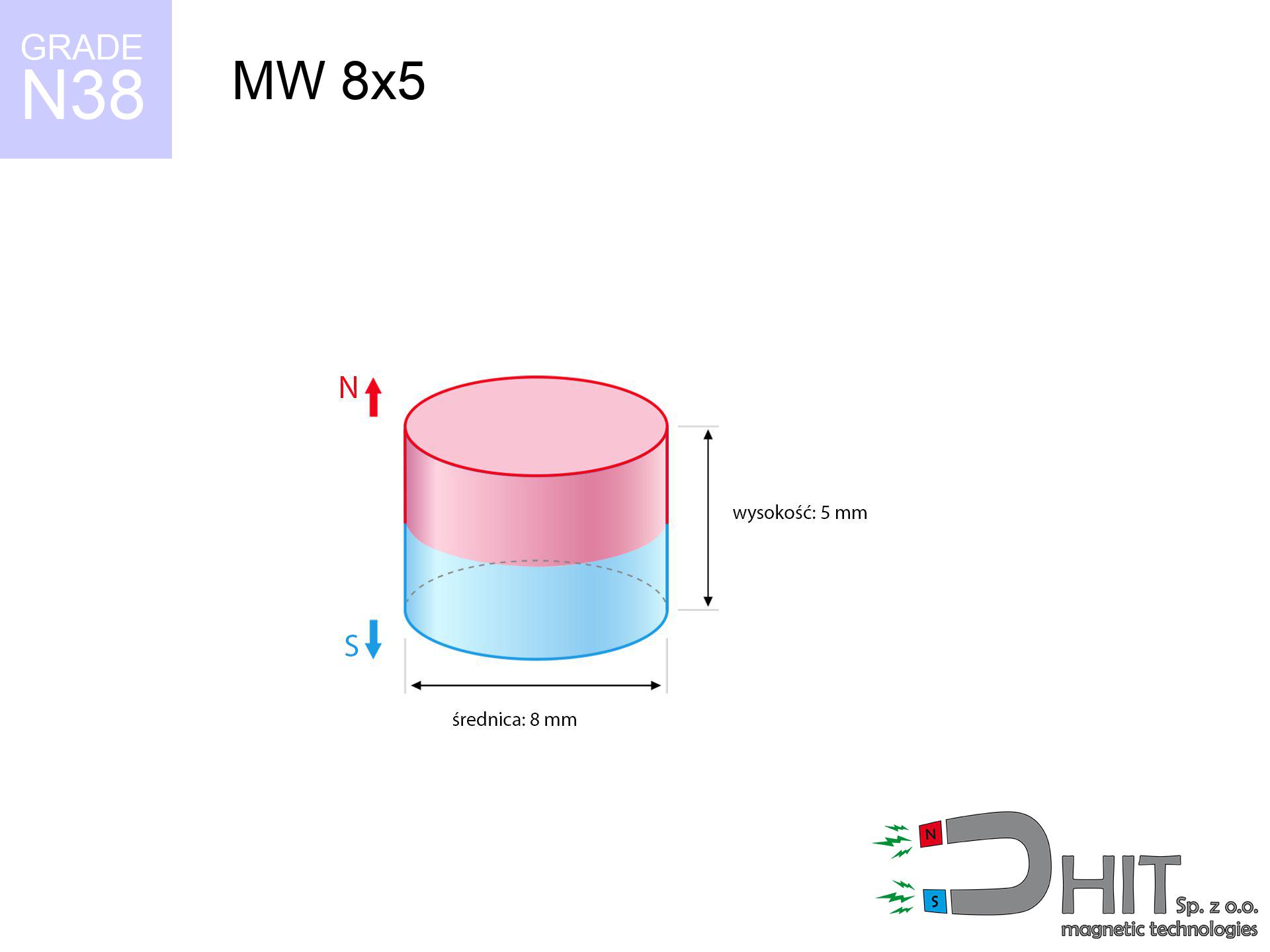
MW 8x5 / N38 - cylindrical magnet
cylindrical magnet
Catalog no 010105
GTIN/EAN: 5906301811046
Diameter Ø
8 mm [±0,1 mm]
Height
5 mm [±0,1 mm]
Weight
1.88 g
Magnetization Direction
↑ axial
Load capacity
2.17 kg / 21.31 N
Magnetic Induction
483.41 mT / 4834 Gs
Coating
[NiCuNi] Nickel
0.836 ZŁ with VAT / pcs + price for transport
0.680 ZŁ net + 23% VAT / pcs
bulk discounts:
Need more?Engineering report for this magnet
Full PDF analysis: pull and shear force, effect of distance, temperature and plate thickness, safety distances and the demagnetization curve.
Give us a call
+48 888 99 98 98
or send us a note through
our online form
our website.
Force along with structure of magnetic components can be calculated with our
online calculation tool.
Order by 14:00 and we’ll ship today!
Technical specification - MW 8x5 / N38 - cylindrical magnet
Specification / characteristics - MW 8x5 / N38 - cylindrical magnet
| properties | values |
|---|---|
| Cat. no. | 010105 |
| GTIN/EAN | 5906301811046 |
| Production/Distribution | Dhit sp. z o.o. |
| Country of origin | Poland / China / Germany |
| Customs code | 85059029 |
| Diameter Ø | 8 mm [±0,1 mm] |
| Height | 5 mm [±0,1 mm] |
| Weight | 1.88 g |
| Magnetization Direction | ↑ axial |
| Load capacity ~ ? | 2.17 kg / 21.31 N |
| Magnetic Induction ~ ? | 483.41 mT / 4834 Gs |
| Coating | [NiCuNi] Nickel |
| Manufacturing Tolerance | ±0.1 mm |
Magnetic properties of material N38
| properties | values | units |
|---|---|---|
| remenance Br [min. - max.] ? | 12.2-12.6 | kGs |
| remenance Br [min. - max.] ? | 1220-1260 | mT |
| coercivity bHc ? | 10.8-11.5 | kOe |
| coercivity bHc ? | 860-915 | kA/m |
| actual internal force iHc | ≥ 12 | kOe |
| actual internal force iHc | ≥ 955 | kA/m |
| energy density [min. - max.] ? | 36-38 | BH max MGOe |
| energy density [min. - max.] ? | 287-303 | BH max KJ/m |
| max. temperature ? | ≤ 80 | °C |
Physical properties of sintered neodymium magnets Nd2Fe14B at 20°C
| properties | values | units |
|---|---|---|
| Vickers hardness | ≥550 | Hv |
| Density | ≥7.4 | g/cm3 |
| Curie Temperature TC | 312 - 380 | °C |
| Curie Temperature TF | 593 - 716 | °F |
| Specific resistance | 150 | μΩ⋅cm |
| Bending strength | 250 | MPa |
| Compressive strength | 1000~1100 | MPa |
| Thermal expansion parallel (∥) to orientation (M) | (3-4) x 10-6 | °C-1 |
| Thermal expansion perpendicular (⊥) to orientation (M) | -(1-3) x 10-6 | °C-1 |
| Young's modulus | 1.7 x 10⁴ | kg/mm² |
Physical analysis of the product - data
The following values are the direct effect of a physical analysis. Values were calculated on algorithms for the class Nd2Fe14B. Actual parameters might slightly differ. Please consider these data as a preliminary roadmap during assembly planning.
Table 1: Static force (force vs distance) - interaction chart
MW 8x5 / N38
| Distance (mm) | Induction (Gauss) / mT | Pull Force (kg/lbs/g/N) | Risk Status |
|---|---|---|---|
| 0 mm |
4830 Gs
483.0 mT
|
2.17 kg / 4.78 pounds
2170.0 g / 21.3 N
|
warning |
| 1 mm |
3655 Gs
365.5 mT
|
1.24 kg / 2.74 pounds
1242.8 g / 12.2 N
|
safe |
| 2 mm |
2610 Gs
261.0 mT
|
0.63 kg / 1.40 pounds
633.9 g / 6.2 N
|
safe |
| 3 mm |
1825 Gs
182.5 mT
|
0.31 kg / 0.68 pounds
310.0 g / 3.0 N
|
safe |
| 5 mm |
915 Gs
91.5 mT
|
0.08 kg / 0.17 pounds
77.9 g / 0.8 N
|
safe |
| 10 mm |
234 Gs
23.4 mT
|
0.01 kg / 0.01 pounds
5.1 g / 0.1 N
|
safe |
| 15 mm |
89 Gs
8.9 mT
|
0.00 kg / 0.00 pounds
0.7 g / 0.0 N
|
safe |
| 20 mm |
43 Gs
4.3 mT
|
0.00 kg / 0.00 pounds
0.2 g / 0.0 N
|
safe |
| 30 mm |
14 Gs
1.4 mT
|
0.00 kg / 0.00 pounds
0.0 g / 0.0 N
|
safe |
| 50 mm |
3 Gs
0.3 mT
|
0.00 kg / 0.00 pounds
0.0 g / 0.0 N
|
safe |
Table 2: Sliding capacity (vertical surface)
MW 8x5 / N38
| Distance (mm) | Friction coefficient | Pull Force (kg/lbs/g/N) |
|---|---|---|
| 0 mm | Stal (~0.2) |
0.43 kg / 0.96 pounds
434.0 g / 4.3 N
|
| 1 mm | Stal (~0.2) |
0.25 kg / 0.55 pounds
248.0 g / 2.4 N
|
| 2 mm | Stal (~0.2) |
0.13 kg / 0.28 pounds
126.0 g / 1.2 N
|
| 3 mm | Stal (~0.2) |
0.06 kg / 0.14 pounds
62.0 g / 0.6 N
|
| 5 mm | Stal (~0.2) |
0.02 kg / 0.04 pounds
16.0 g / 0.2 N
|
| 10 mm | Stal (~0.2) |
0.00 kg / 0.00 pounds
2.0 g / 0.0 N
|
| 15 mm | Stal (~0.2) |
0.00 kg / 0.00 pounds
0.0 g / 0.0 N
|
| 20 mm | Stal (~0.2) |
0.00 kg / 0.00 pounds
0.0 g / 0.0 N
|
| 30 mm | Stal (~0.2) |
0.00 kg / 0.00 pounds
0.0 g / 0.0 N
|
| 50 mm | Stal (~0.2) |
0.00 kg / 0.00 pounds
0.0 g / 0.0 N
|
Table 3: Vertical assembly (shearing) - vertical pull
MW 8x5 / N38
| Surface type | Friction coefficient / % Mocy | Max load (kg/lbs/g/N) |
|---|---|---|
| Raw steel |
µ = 0.3
30% Nominalnej Siły
|
0.65 kg / 1.44 pounds
651.0 g / 6.4 N
|
| Painted steel (standard) |
µ = 0.2
20% Nominalnej Siły
|
0.43 kg / 0.96 pounds
434.0 g / 4.3 N
|
| Oily/slippery steel |
µ = 0.1
10% Nominalnej Siły
|
0.22 kg / 0.48 pounds
217.0 g / 2.1 N
|
| Magnet with anti-slip rubber |
µ = 0.5
50% Nominalnej Siły
|
1.09 kg / 2.39 pounds
1085.0 g / 10.6 N
|
Table 4: Steel thickness (saturation) - power losses
MW 8x5 / N38
| Steel thickness (mm) | % power | Real pull force (kg/lbs/g/N) |
|---|---|---|
| 0.5 mm |
|
0.22 kg / 0.48 pounds
217.0 g / 2.1 N
|
| 1 mm |
|
0.54 kg / 1.20 pounds
542.5 g / 5.3 N
|
| 2 mm |
|
1.09 kg / 2.39 pounds
1085.0 g / 10.6 N
|
| 3 mm |
|
1.63 kg / 3.59 pounds
1627.5 g / 16.0 N
|
| 5 mm |
|
2.17 kg / 4.78 pounds
2170.0 g / 21.3 N
|
| 10 mm |
|
2.17 kg / 4.78 pounds
2170.0 g / 21.3 N
|
| 11 mm |
|
2.17 kg / 4.78 pounds
2170.0 g / 21.3 N
|
| 12 mm |
|
2.17 kg / 4.78 pounds
2170.0 g / 21.3 N
|
Table 5: Thermal resistance (material behavior) - thermal limit
MW 8x5 / N38
| Ambient temp. (°C) | Power loss | Remaining pull (kg/lbs/g/N) | Status |
|---|---|---|---|
| 20 °C | 0.0% |
2.17 kg / 4.78 pounds
2170.0 g / 21.3 N
|
OK |
| 40 °C | -2.2% |
2.12 kg / 4.68 pounds
2122.3 g / 20.8 N
|
OK |
| 60 °C | -4.4% |
2.07 kg / 4.57 pounds
2074.5 g / 20.4 N
|
OK |
| 80 °C | -6.6% |
2.03 kg / 4.47 pounds
2026.8 g / 19.9 N
|
|
| 100 °C | -28.8% |
1.55 kg / 3.41 pounds
1545.0 g / 15.2 N
|
Table 6: Magnet-Magnet interaction (repulsion) - forces in the system
MW 8x5 / N38
| Gap (mm) | Attraction (kg/lbs) (N-S) | Shear Force (kg/lbs/g/N) | Repulsion (kg/lbs) (N-N) |
|---|---|---|---|
| 0 mm |
7.23 kg / 15.94 pounds
5 742 Gs
|
1.08 kg / 2.39 pounds
1084 g / 10.6 N
|
N/A |
| 1 mm |
5.58 kg / 12.31 pounds
8 490 Gs
|
0.84 kg / 1.85 pounds
838 g / 8.2 N
|
5.03 kg / 11.08 pounds
~0 Gs
|
| 2 mm |
4.14 kg / 9.13 pounds
7 310 Gs
|
0.62 kg / 1.37 pounds
621 g / 6.1 N
|
3.73 kg / 8.21 pounds
~0 Gs
|
| 3 mm |
2.98 kg / 6.58 pounds
6 207 Gs
|
0.45 kg / 0.99 pounds
448 g / 4.4 N
|
2.69 kg / 5.92 pounds
~0 Gs
|
| 5 mm |
1.48 kg / 3.26 pounds
4 369 Gs
|
0.22 kg / 0.49 pounds
222 g / 2.2 N
|
1.33 kg / 2.93 pounds
~0 Gs
|
| 10 mm |
0.26 kg / 0.57 pounds
1 830 Gs
|
0.04 kg / 0.09 pounds
39 g / 0.4 N
|
0.23 kg / 0.51 pounds
~0 Gs
|
| 20 mm |
0.02 kg / 0.04 pounds
468 Gs
|
0.00 kg / 0.01 pounds
3 g / 0.0 N
|
0.02 kg / 0.03 pounds
~0 Gs
|
| 50 mm |
0.00 kg / 0.00 pounds
47 Gs
|
0.00 kg / 0.00 pounds
0 g / 0.0 N
|
0.00 kg / 0.00 pounds
~0 Gs
|
| 60 mm |
0.00 kg / 0.00 pounds
29 Gs
|
0.00 kg / 0.00 pounds
0 g / 0.0 N
|
0.00 kg / 0.00 pounds
~0 Gs
|
| 70 mm |
0.00 kg / 0.00 pounds
19 Gs
|
0.00 kg / 0.00 pounds
0 g / 0.0 N
|
0.00 kg / 0.00 pounds
~0 Gs
|
| 80 mm |
0.00 kg / 0.00 pounds
13 Gs
|
0.00 kg / 0.00 pounds
0 g / 0.0 N
|
0.00 kg / 0.00 pounds
~0 Gs
|
| 90 mm |
0.00 kg / 0.00 pounds
9 Gs
|
0.00 kg / 0.00 pounds
0 g / 0.0 N
|
0.00 kg / 0.00 pounds
~0 Gs
|
| 100 mm |
0.00 kg / 0.00 pounds
7 Gs
|
0.00 kg / 0.00 pounds
0 g / 0.0 N
|
0.00 kg / 0.00 pounds
~0 Gs
|
Table 7: Hazards (electronics) - precautionary measures
MW 8x5 / N38
| Object / Device | Limit (Gauss) / mT | Safe distance |
|---|---|---|
| Pacemaker | 5 Gs (0.5 mT) | 4.5 cm |
| Hearing aid | 10 Gs (1.0 mT) | 3.5 cm |
| Mechanical watch | 20 Gs (2.0 mT) | 3.0 cm |
| Mobile device | 40 Gs (4.0 mT) | 2.5 cm |
| Car key | 50 Gs (5.0 mT) | 2.0 cm |
| Payment card | 400 Gs (40.0 mT) | 1.0 cm |
| HDD hard drive | 600 Gs (60.0 mT) | 1.0 cm |
Table 8: Collisions (cracking risk) - warning
MW 8x5 / N38
| Start from (mm) | Speed (km/h) | Energy (J) | Predicted outcome |
|---|---|---|---|
| 10 mm |
34.31 km/h
(9.53 m/s)
|
0.09 J | |
| 30 mm |
59.35 km/h
(16.49 m/s)
|
0.26 J | |
| 50 mm |
76.62 km/h
(21.28 m/s)
|
0.43 J | |
| 100 mm |
108.35 km/h
(30.10 m/s)
|
0.85 J |
Table 9: Coating parameters (durability)
MW 8x5 / N38
| Technical parameter | Value / Description |
|---|---|
| Coating type | [NiCuNi] Nickel |
| Layer structure | Nickel - Copper - Nickel |
| Layer thickness | 10-20 µm |
| Salt spray test (SST) ? | 24 h |
| Recommended environment | Indoors only (dry) |
Table 10: Construction data (Flux)
MW 8x5 / N38
| Parameter | Value | SI Unit / Description |
|---|---|---|
| Magnetic Flux | 2 450 Mx | 24.5 µWb |
| Pc Coefficient | 0.68 | High (Stable) |
Table 11: Submerged application
MW 8x5 / N38
| Environment | Effective steel pull | Effect |
|---|---|---|
| Air (land) | 2.17 kg | Standard |
| Water (riverbed) |
2.48 kg
(+0.31 kg buoyancy gain)
|
+14.5% |
1. Shear force
*Warning: On a vertical wall, the magnet retains just approx. 20-30% of its nominal pull.
2. Efficiency vs thickness
*Thin steel (e.g. computer case) drastically weakens the holding force.
3. Thermal stability
*For N38 material, the critical limit is 80°C.
4. Demagnetization curve and operating point (B-H)
chart generated for the permeance coefficient Pc (Permeance Coefficient) = 0.68
The chart above illustrates the magnetic characteristics of the material within the second quadrant of the hysteresis loop. The solid red line represents the demagnetization curve (material potential), while the dashed blue line is the load line based on the magnet's geometry. The Pc (Permeance Coefficient), also known as the load line slope, is a dimensionless value that describes the relationship between the magnet's shape and its magnetic stability. The intersection of these two lines (the black dot) is the operating point — it determines the actual magnetic flux density generated by the magnet in this specific configuration. A higher Pc value means the magnet is more 'slender' (tall relative to its area), resulting in a higher operating point and better resistance to irreversible demagnetization caused by external fields or temperature. A value of 0.42 is relatively low (typical for flat magnets), meaning the operating point is closer to the 'knee' of the curve — caution is advised when operating at temperatures near the maximum limit to avoid strength loss.
Chemical composition
| iron (Fe) | 64% – 68% |
| neodymium (Nd) | 29% – 32% |
| boron (B) | 1.1% – 1.2% |
| dysprosium (Dy) | 0.5% – 2.0% |
| coating (Ni-Cu-Ni) | < 0.05% |
Environmental data
| recyclability (EoL) | 100% |
| recycled raw materials | ~10% (pre-cons) |
| carbon footprint | low / zredukowany |
| waste code (EWC) | 16 02 16 |
View also products
![SM 32x150 [2xM8] / N52 - magnetic separator](https://cdn3.dhit.pl/graphics/products/sm-32x150-2xm8-xuc.jpg "SM 32x150 [2xM8] / N52 - magnetic separator")

![UMP 135x40 [M10+M12] GW F600 Lina / N38 - search holder](https://cdn3.dhit.pl/graphics/products/ump-135x40-m10+m12-gw-f600-+lina-sej.jpg "UMP 135x40 [M10+M12] GW F600 Lina / N38 - search holder")

Advantages as well as disadvantages of rare earth magnets.
Pros
- They have unchanged lifting capacity, and over nearly 10 years their attraction force decreases symbolically – ~1% (in testing),
- Neodymium magnets prove to be exceptionally resistant to loss of magnetic properties caused by external field sources,
- Thanks to the smooth finish, the coating of nickel, gold, or silver gives an professional appearance,
- Magnets possess impressive magnetic induction on the active area,
- Made from properly selected components, these magnets show impressive resistance to high heat, enabling them to function (depending on their form) at temperatures up to 230°C and above...
- Thanks to flexibility in constructing and the ability to customize to unusual requirements,
- Key role in high-tech industry – they find application in HDD drives, motor assemblies, diagnostic systems, and complex engineering applications.
- Thanks to their power density, small magnets offer high operating force, with minimal size,
Disadvantages
- They are prone to damage upon heavy impacts. To avoid cracks, it is worth protecting magnets using a steel holder. Such protection not only protects the magnet but also increases its resistance to damage
- Neodymium magnets lose their strength under the influence of heating. As soon as 80°C is exceeded, many of them start losing their force. Therefore, we recommend our special magnets marked [AH], which maintain stability even at temperatures up to 230°C
- Due to the susceptibility of magnets to corrosion in a humid environment, we suggest using waterproof magnets made of rubber, plastic or other material immune to moisture, when using outdoors
- We recommend casing - magnetic mechanism, due to difficulties in producing nuts inside the magnet and complicated shapes.
- Possible danger resulting from small fragments of magnets are risky, if swallowed, which is particularly important in the context of child health protection. Furthermore, small elements of these magnets are able to disrupt the diagnostic process medical in case of swallowing.
- Due to neodymium price, their price exceeds standard values,
Holding force characteristics
Detachment force of the magnet in optimal conditions – what affects it?
- using a plate made of low-carbon steel, serving as a magnetic yoke
- whose transverse dimension reaches at least 10 mm
- characterized by smoothness
- with total lack of distance (without impurities)
- during pulling in a direction perpendicular to the mounting surface
- at standard ambient temperature
Determinants of practical lifting force of a magnet
- Distance (betwixt the magnet and the plate), as even a tiny clearance (e.g. 0.5 mm) can cause a reduction in force by up to 50% (this also applies to paint, rust or debris).
- Pull-off angle – note that the magnet has greatest strength perpendicularly. Under sliding down, the holding force drops significantly, often to levels of 20-30% of the nominal value.
- Steel thickness – insufficiently thick plate does not close the flux, causing part of the power to be wasted into the air.
- Material composition – different alloys attracts identically. Alloy additives worsen the interaction with the magnet.
- Surface condition – ground elements guarantee perfect abutment, which increases force. Rough surfaces reduce efficiency.
- Heat – neodymium magnets have a sensitivity to temperature. At higher temperatures they are weaker, and at low temperatures they can be stronger (up to a certain limit).
Lifting capacity testing was conducted on plates with a smooth surface of optimal thickness, under perpendicular forces, in contrast under parallel forces the lifting capacity is smaller. Moreover, even a minimal clearance between the magnet and the plate decreases the holding force.
Safe handling of neodymium magnets
Health Danger
Health Alert: Strong magnets can deactivate pacemakers and defibrillators. Stay away if you have medical devices.
Beware of splinters
Neodymium magnets are ceramic materials, which means they are very brittle. Impact of two magnets will cause them cracking into small pieces.
Data carriers
Very strong magnetic fields can corrupt files on payment cards, HDDs, and storage devices. Keep a distance of min. 10 cm.
Permanent damage
Regular neodymium magnets (grade N) lose magnetization when the temperature exceeds 80°C. Damage is permanent.
Fire warning
Powder produced during grinding of magnets is combustible. Do not drill into magnets without proper cooling and knowledge.
Adults only
Absolutely keep magnets out of reach of children. Risk of swallowing is significant, and the consequences of magnets connecting inside the body are very dangerous.
Physical harm
Big blocks can break fingers instantly. Under no circumstances put your hand between two strong magnets.
Powerful field
Handle with care. Rare earth magnets attract from a distance and connect with huge force, often faster than you can react.
Skin irritation risks
Nickel alert: The Ni-Cu-Ni coating contains nickel. If redness occurs, cease working with magnets and use protective gear.
Keep away from electronics
Note: rare earth magnets produce a field that disrupts sensitive sensors. Maintain a separation from your phone, tablet, and GPS.
Tabela kosztu i czasu dostawy
Płatność przed wysyłką:

GLS kurier
Przesyłka będzie u Ciebie za 2-3 dni
14.99 ZŁ

InPost Paczkomaty 24/7
Przesyłka będzie u Ciebie za 1-2 dni
12.30 ZŁ
Płatność przy odbiorze (pobranie):
GLS kurier
Przesyłka będzie u Ciebie za 1-2 dni
23.00 ZŁ
Rate the product
Your rating