

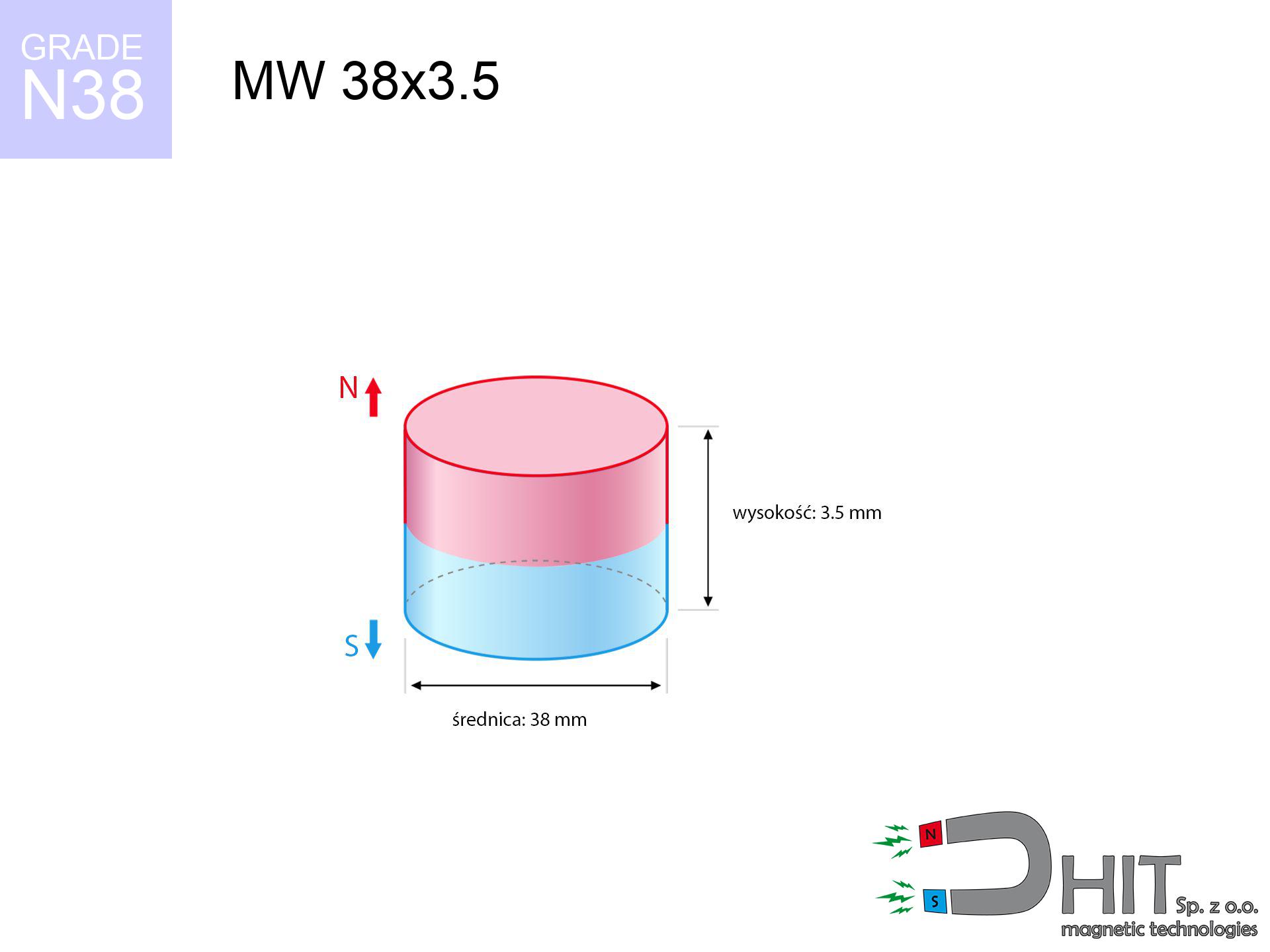
MW 38x3.5 / N38 - cylindrical magnet
cylindrical magnet
Catalog no 010062
GTIN/EAN: 5906301810612
Diameter Ø
38 mm [±0,1 mm]
Height
3.5 mm [±0,1 mm]
Weight
29.77 g
Magnetization Direction
↑ axial
Load capacity
5.09 kg / 49.91 N
Magnetic Induction
112.31 mT / 1123 Gs
Coating
[NiCuNi] Nickel
15.83 ZŁ with VAT / pcs + price for transport
12.87 ZŁ net + 23% VAT / pcs
bulk discounts:
Need more?Engineering report for this magnet
Full PDF analysis: pull and shear force, effect of distance, temperature and plate thickness, safety distances and the demagnetization curve.
Call us now
+48 888 99 98 98
if you prefer drop us a message via
form
the contact form page.
Lifting power as well as appearance of neodymium magnets can be calculated using our
modular calculator.
Orders placed before 14:00 will be shipped the same business day.
Physical properties - MW 38x3.5 / N38 - cylindrical magnet
Specification / characteristics - MW 38x3.5 / N38 - cylindrical magnet
| properties | values |
|---|---|
| Cat. no. | 010062 |
| GTIN/EAN | 5906301810612 |
| Production/Distribution | Dhit sp. z o.o. |
| Country of origin | Poland / China / Germany |
| Customs code | 85059029 |
| Diameter Ø | 38 mm [±0,1 mm] |
| Height | 3.5 mm [±0,1 mm] |
| Weight | 29.77 g |
| Magnetization Direction | ↑ axial |
| Load capacity ~ ? | 5.09 kg / 49.91 N |
| Magnetic Induction ~ ? | 112.31 mT / 1123 Gs |
| Coating | [NiCuNi] Nickel |
| Manufacturing Tolerance | ±0.1 mm |
Magnetic properties of material N38
| properties | values | units |
|---|---|---|
| remenance Br [min. - max.] ? | 12.2-12.6 | kGs |
| remenance Br [min. - max.] ? | 1220-1260 | mT |
| coercivity bHc ? | 10.8-11.5 | kOe |
| coercivity bHc ? | 860-915 | kA/m |
| actual internal force iHc | ≥ 12 | kOe |
| actual internal force iHc | ≥ 955 | kA/m |
| energy density [min. - max.] ? | 36-38 | BH max MGOe |
| energy density [min. - max.] ? | 287-303 | BH max KJ/m |
| max. temperature ? | ≤ 80 | °C |
Physical properties of sintered neodymium magnets Nd2Fe14B at 20°C
| properties | values | units |
|---|---|---|
| Vickers hardness | ≥550 | Hv |
| Density | ≥7.4 | g/cm3 |
| Curie Temperature TC | 312 - 380 | °C |
| Curie Temperature TF | 593 - 716 | °F |
| Specific resistance | 150 | μΩ⋅cm |
| Bending strength | 250 | MPa |
| Compressive strength | 1000~1100 | MPa |
| Thermal expansion parallel (∥) to orientation (M) | (3-4) x 10-6 | °C-1 |
| Thermal expansion perpendicular (⊥) to orientation (M) | -(1-3) x 10-6 | °C-1 |
| Young's modulus | 1.7 x 10⁴ | kg/mm² |
Engineering modeling of the magnet - report
Presented data are the result of a mathematical calculation. Results are based on models for the material Nd2Fe14B. Real-world performance may differ. Please consider these data as a preliminary roadmap for designers.
Table 1: Static force (pull vs gap) - characteristics
MW 38x3.5 / N38
| Distance (mm) | Induction (Gauss) / mT | Pull Force (kg/lbs/g/N) | Risk Status |
|---|---|---|---|
| 0 mm |
1123 Gs
112.3 mT
|
5.09 kg / 11.22 LBS
5090.0 g / 49.9 N
|
strong |
| 1 mm |
1103 Gs
110.3 mT
|
4.91 kg / 10.82 LBS
4910.1 g / 48.2 N
|
strong |
| 2 mm |
1075 Gs
107.5 mT
|
4.66 kg / 10.28 LBS
4663.0 g / 45.7 N
|
strong |
| 3 mm |
1040 Gs
104.0 mT
|
4.36 kg / 9.62 LBS
4364.2 g / 42.8 N
|
strong |
| 5 mm |
954 Gs
95.4 mT
|
3.67 kg / 8.10 LBS
3673.1 g / 36.0 N
|
strong |
| 10 mm |
703 Gs
70.3 mT
|
2.00 kg / 4.40 LBS
1997.1 g / 19.6 N
|
safe |
| 15 mm |
483 Gs
48.3 mT
|
0.94 kg / 2.08 LBS
943.2 g / 9.3 N
|
safe |
| 20 mm |
326 Gs
32.6 mT
|
0.43 kg / 0.95 LBS
429.7 g / 4.2 N
|
safe |
| 30 mm |
155 Gs
15.5 mT
|
0.10 kg / 0.21 LBS
97.1 g / 1.0 N
|
safe |
| 50 mm |
47 Gs
4.7 mT
|
0.01 kg / 0.02 LBS
8.9 g / 0.1 N
|
safe |
Table 2: Sliding hold (vertical surface)
MW 38x3.5 / N38
| Distance (mm) | Friction coefficient | Pull Force (kg/lbs/g/N) |
|---|---|---|
| 0 mm | Stal (~0.2) |
1.02 kg / 2.24 LBS
1018.0 g / 10.0 N
|
| 1 mm | Stal (~0.2) |
0.98 kg / 2.16 LBS
982.0 g / 9.6 N
|
| 2 mm | Stal (~0.2) |
0.93 kg / 2.05 LBS
932.0 g / 9.1 N
|
| 3 mm | Stal (~0.2) |
0.87 kg / 1.92 LBS
872.0 g / 8.6 N
|
| 5 mm | Stal (~0.2) |
0.73 kg / 1.62 LBS
734.0 g / 7.2 N
|
| 10 mm | Stal (~0.2) |
0.40 kg / 0.88 LBS
400.0 g / 3.9 N
|
| 15 mm | Stal (~0.2) |
0.19 kg / 0.41 LBS
188.0 g / 1.8 N
|
| 20 mm | Stal (~0.2) |
0.09 kg / 0.19 LBS
86.0 g / 0.8 N
|
| 30 mm | Stal (~0.2) |
0.02 kg / 0.04 LBS
20.0 g / 0.2 N
|
| 50 mm | Stal (~0.2) |
0.00 kg / 0.00 LBS
2.0 g / 0.0 N
|
Table 3: Wall mounting (shearing) - vertical pull
MW 38x3.5 / N38
| Surface type | Friction coefficient / % Mocy | Max load (kg/lbs/g/N) |
|---|---|---|
| Raw steel |
µ = 0.3
30% Nominalnej Siły
|
1.53 kg / 3.37 LBS
1527.0 g / 15.0 N
|
| Painted steel (standard) |
µ = 0.2
20% Nominalnej Siły
|
1.02 kg / 2.24 LBS
1018.0 g / 10.0 N
|
| Oily/slippery steel |
µ = 0.1
10% Nominalnej Siły
|
0.51 kg / 1.12 LBS
509.0 g / 5.0 N
|
| Magnet with anti-slip rubber |
µ = 0.5
50% Nominalnej Siły
|
2.55 kg / 5.61 LBS
2545.0 g / 25.0 N
|
Table 4: Material efficiency (saturation) - power losses
MW 38x3.5 / N38
| Steel thickness (mm) | % power | Real pull force (kg/lbs/g/N) |
|---|---|---|
| 0.5 mm |
|
0.51 kg / 1.12 LBS
509.0 g / 5.0 N
|
| 1 mm |
|
1.27 kg / 2.81 LBS
1272.5 g / 12.5 N
|
| 2 mm |
|
2.55 kg / 5.61 LBS
2545.0 g / 25.0 N
|
| 3 mm |
|
3.82 kg / 8.42 LBS
3817.5 g / 37.4 N
|
| 5 mm |
|
5.09 kg / 11.22 LBS
5090.0 g / 49.9 N
|
| 10 mm |
|
5.09 kg / 11.22 LBS
5090.0 g / 49.9 N
|
| 11 mm |
|
5.09 kg / 11.22 LBS
5090.0 g / 49.9 N
|
| 12 mm |
|
5.09 kg / 11.22 LBS
5090.0 g / 49.9 N
|
Table 5: Thermal resistance (stability) - thermal limit
MW 38x3.5 / N38
| Ambient temp. (°C) | Power loss | Remaining pull (kg/lbs/g/N) | Status |
|---|---|---|---|
| 20 °C | 0.0% |
5.09 kg / 11.22 LBS
5090.0 g / 49.9 N
|
OK |
| 40 °C | -2.2% |
4.98 kg / 10.97 LBS
4978.0 g / 48.8 N
|
OK |
| 60 °C | -4.4% |
4.87 kg / 10.73 LBS
4866.0 g / 47.7 N
|
|
| 80 °C | -6.6% |
4.75 kg / 10.48 LBS
4754.1 g / 46.6 N
|
|
| 100 °C | -28.8% |
3.62 kg / 7.99 LBS
3624.1 g / 35.6 N
|
Table 6: Two magnets (attraction) - forces in the system
MW 38x3.5 / N38
| Gap (mm) | Attraction (kg/lbs) (N-S) | Sliding Force (kg/lbs/g/N) | Repulsion (kg/lbs) (N-N) |
|---|---|---|---|
| 0 mm |
8.82 kg / 19.44 LBS
2 143 Gs
|
1.32 kg / 2.92 LBS
1323 g / 13.0 N
|
N/A |
| 1 mm |
8.68 kg / 19.13 LBS
2 228 Gs
|
1.30 kg / 2.87 LBS
1302 g / 12.8 N
|
7.81 kg / 17.22 LBS
~0 Gs
|
| 2 mm |
8.51 kg / 18.75 LBS
2 206 Gs
|
1.28 kg / 2.81 LBS
1276 g / 12.5 N
|
7.66 kg / 16.88 LBS
~0 Gs
|
| 3 mm |
8.31 kg / 18.31 LBS
2 180 Gs
|
1.25 kg / 2.75 LBS
1246 g / 12.2 N
|
7.47 kg / 16.48 LBS
~0 Gs
|
| 5 mm |
7.83 kg / 17.26 LBS
2 116 Gs
|
1.17 kg / 2.59 LBS
1174 g / 11.5 N
|
7.05 kg / 15.53 LBS
~0 Gs
|
| 10 mm |
6.36 kg / 14.03 LBS
1 908 Gs
|
0.95 kg / 2.10 LBS
955 g / 9.4 N
|
5.73 kg / 12.63 LBS
~0 Gs
|
| 20 mm |
3.46 kg / 7.63 LBS
1 407 Gs
|
0.52 kg / 1.14 LBS
519 g / 5.1 N
|
3.11 kg / 6.87 LBS
~0 Gs
|
| 50 mm |
0.35 kg / 0.76 LBS
445 Gs
|
0.05 kg / 0.11 LBS
52 g / 0.5 N
|
0.31 kg / 0.69 LBS
~0 Gs
|
| 60 mm |
0.17 kg / 0.37 LBS
310 Gs
|
0.03 kg / 0.06 LBS
25 g / 0.2 N
|
0.15 kg / 0.33 LBS
~0 Gs
|
| 70 mm |
0.09 kg / 0.19 LBS
222 Gs
|
0.01 kg / 0.03 LBS
13 g / 0.1 N
|
0.08 kg / 0.17 LBS
~0 Gs
|
| 80 mm |
0.05 kg / 0.10 LBS
163 Gs
|
0.01 kg / 0.02 LBS
7 g / 0.1 N
|
0.04 kg / 0.09 LBS
~0 Gs
|
| 90 mm |
0.03 kg / 0.06 LBS
122 Gs
|
0.00 kg / 0.01 LBS
4 g / 0.0 N
|
0.02 kg / 0.05 LBS
~0 Gs
|
| 100 mm |
0.02 kg / 0.03 LBS
94 Gs
|
0.00 kg / 0.01 LBS
2 g / 0.0 N
|
0.01 kg / 0.03 LBS
~0 Gs
|
Table 7: Safety (HSE) (electronics) - warnings
MW 38x3.5 / N38
| Object / Device | Limit (Gauss) / mT | Safe distance |
|---|---|---|
| Pacemaker | 5 Gs (0.5 mT) | 11.5 cm |
| Hearing aid | 10 Gs (1.0 mT) | 9.0 cm |
| Mechanical watch | 20 Gs (2.0 mT) | 7.0 cm |
| Phone / Smartphone | 40 Gs (4.0 mT) | 5.5 cm |
| Car key | 50 Gs (5.0 mT) | 5.0 cm |
| Payment card | 400 Gs (40.0 mT) | 2.0 cm |
| HDD hard drive | 600 Gs (60.0 mT) | 1.5 cm |
Table 8: Impact energy (cracking risk) - collision effects
MW 38x3.5 / N38
| Start from (mm) | Speed (km/h) | Energy (J) | Predicted outcome |
|---|---|---|---|
| 10 mm |
16.10 km/h
(4.47 m/s)
|
0.30 J | |
| 30 mm |
23.11 km/h
(6.42 m/s)
|
0.61 J | |
| 50 mm |
29.52 km/h
(8.20 m/s)
|
1.00 J | |
| 100 mm |
41.70 km/h
(11.58 m/s)
|
2.00 J |
Table 9: Coating parameters (durability)
MW 38x3.5 / N38
| Technical parameter | Value / Description |
|---|---|
| Coating type | [NiCuNi] Nickel |
| Layer structure | Nickel - Copper - Nickel |
| Layer thickness | 10-20 µm |
| Salt spray test (SST) ? | 24 h |
| Recommended environment | Indoors only (dry) |
Table 10: Electrical data (Pc)
MW 38x3.5 / N38
| Parameter | Value | SI Unit / Description |
|---|---|---|
| Magnetic Flux | 17 022 Mx | 170.2 µWb |
| Pc Coefficient | 0.14 | Low (Flat) |
Table 11: Underwater work (magnet fishing)
MW 38x3.5 / N38
| Environment | Effective steel pull | Effect |
|---|---|---|
| Air (land) | 5.09 kg | Standard |
| Water (riverbed) |
5.83 kg
(+0.74 kg buoyancy gain)
|
+14.5% |
1. Vertical hold
*Note: On a vertical surface, the magnet holds merely a fraction of its nominal pull.
2. Efficiency vs thickness
*Thin steel (e.g. 0.5mm PC case) drastically limits the holding force.
3. Power loss vs temp
*For N38 material, the max working temp is 80°C.
4. Demagnetization curve and operating point (B-H)
chart generated for the permeance coefficient Pc (Permeance Coefficient) = 0.14
This simulation demonstrates the magnetic stability of the selected magnet under specific geometric conditions. The solid red line represents the demagnetization curve (material potential), while the dashed blue line is the load line based on the magnet's geometry. The Pc (Permeance Coefficient), also known as the load line slope, is a dimensionless value that describes the relationship between the magnet's shape and its magnetic stability. The intersection of these two lines (the black dot) is the operating point — it determines the actual magnetic flux density generated by the magnet in this specific configuration. A higher Pc value means the magnet is more 'slender' (tall relative to its area), resulting in a higher operating point and better resistance to irreversible demagnetization caused by external fields or temperature. A value of 0.42 is relatively low (typical for flat magnets), meaning the operating point is closer to the 'knee' of the curve — caution is advised when operating at temperatures near the maximum limit to avoid strength loss.
Material specification
| iron (Fe) | 64% – 68% |
| neodymium (Nd) | 29% – 32% |
| boron (B) | 1.1% – 1.2% |
| dysprosium (Dy) | 0.5% – 2.0% |
| coating (Ni-Cu-Ni) | < 0.05% |
Environmental data
| recyclability (EoL) | 100% |
| recycled raw materials | ~10% (pre-cons) |
| carbon footprint | low / zredukowany |
| waste code (EWC) | 16 02 16 |
Other deals

![MPL 40x10x5x2[7/3.5] / N38 - lamellar magnet](https://cdn3.dhit.pl/graphics/products/mpl-40x10x5x27-3.5-miw.jpg "MPL 40x10x5x2[7/3.5] / N38 - lamellar magnet")
![SM 25x250 [2xM8] / N42 - magnetic separator](https://cdn3.dhit.pl/graphics/products/sm-25x250-2xm8-ker.jpg "SM 25x250 [2xM8] / N42 - magnetic separator")

Advantages as well as disadvantages of Nd2Fe14B magnets.
Pros
- Their strength is maintained, and after around ten years it drops only by ~1% (according to research),
- Magnets perfectly protect themselves against demagnetization caused by ambient magnetic noise,
- Thanks to the reflective finish, the layer of nickel, gold, or silver-plated gives an modern appearance,
- They feature high magnetic induction at the operating surface, which affects their effectiveness,
- Neodymium magnets are characterized by very high magnetic induction on the magnet surface and can function (depending on the shape) even at a temperature of 230°C or more...
- Thanks to freedom in forming and the capacity to customize to client solutions,
- Fundamental importance in future technologies – they are utilized in data components, electromotive mechanisms, precision medical tools, as well as industrial machines.
- Thanks to concentrated force, small magnets offer high operating force, with minimal size,
Disadvantages
- Susceptibility to cracking is one of their disadvantages. Upon intense impact they can fracture. We recommend keeping them in a strong case, which not only protects them against impacts but also increases their durability
- We warn that neodymium magnets can lose their power at high temperatures. To prevent this, we recommend our specialized [AH] magnets, which work effectively even at 230°C.
- Due to the susceptibility of magnets to corrosion in a humid environment, we recommend using waterproof magnets made of rubber, plastic or other material resistant to moisture, when using outdoors
- Limited possibility of creating nuts in the magnet and complex forms - preferred is cover - magnet mounting.
- Possible danger resulting from small fragments of magnets are risky, when accidentally swallowed, which is particularly important in the aspect of protecting the youngest. Furthermore, small elements of these products can disrupt the diagnostic process medical when they are in the body.
- High unit price – neodymium magnets cost more than other types of magnets (e.g. ferrite), which increases costs of application in large quantities
Pull force analysis
Detachment force of the magnet in optimal conditions – what affects it?
- with the contact of a sheet made of special test steel, ensuring full magnetic saturation
- whose transverse dimension equals approx. 10 mm
- with a plane free of scratches
- without any air gap between the magnet and steel
- for force applied at a right angle (pull-off, not shear)
- in stable room temperature
Lifting capacity in real conditions – factors
- Gap between surfaces – even a fraction of a millimeter of distance (caused e.g. by veneer or unevenness) diminishes the pulling force, often by half at just 0.5 mm.
- Loading method – catalog parameter refers to detachment vertically. When applying parallel force, the magnet exhibits significantly lower power (often approx. 20-30% of nominal force).
- Metal thickness – thin material does not allow full use of the magnet. Magnetic flux passes through the material instead of converting into lifting capacity.
- Metal type – different alloys attracts identically. High carbon content worsen the interaction with the magnet.
- Surface finish – ideal contact is obtained only on smooth steel. Any scratches and bumps reduce the real contact area, reducing force.
- Heat – neodymium magnets have a sensitivity to temperature. At higher temperatures they lose power, and in frost gain strength (up to a certain limit).
Holding force was measured on a smooth steel plate of 20 mm thickness, when a perpendicular force was applied, however under attempts to slide the magnet the holding force is lower. Moreover, even a small distance between the magnet and the plate reduces the load capacity.
Safety rules for work with NdFeB magnets
Finger safety
Mind your fingers. Two powerful magnets will snap together immediately with a force of massive weight, crushing anything in their path. Be careful!
Electronic devices
Very strong magnetic fields can corrupt files on payment cards, hard drives, and other magnetic media. Maintain a gap of at least 10 cm.
Health Danger
For implant holders: Powerful magnets affect medical devices. Maintain at least 30 cm distance or request help to work with the magnets.
Caution required
Use magnets with awareness. Their immense force can surprise even professionals. Be vigilant and respect their power.
Do not give to children
These products are not suitable for play. Eating multiple magnets can lead to them attracting across intestines, which constitutes a direct threat to life and necessitates urgent medical intervention.
Shattering risk
NdFeB magnets are sintered ceramics, which means they are prone to chipping. Collision of two magnets leads to them shattering into small pieces.
Flammability
Powder produced during cutting of magnets is flammable. Avoid drilling into magnets without proper cooling and knowledge.
Heat sensitivity
Regular neodymium magnets (N-type) undergo demagnetization when the temperature exceeds 80°C. Damage is permanent.
Metal Allergy
Allergy Notice: The nickel-copper-nickel coating contains nickel. If an allergic reaction happens, immediately stop working with magnets and use protective gear.
Precision electronics
Navigation devices and mobile phones are extremely sensitive to magnetism. Direct contact with a powerful NdFeB magnet can permanently damage the sensors in your phone.
Tabela kosztu i czasu dostawy
Płatność przed wysyłką:

GLS kurier
Przesyłka będzie u Ciebie za 2-3 dni
14.99 ZŁ

InPost Paczkomaty 24/7
Przesyłka będzie u Ciebie za 1-2 dni
12.30 ZŁ
Płatność przy odbiorze (pobranie):
GLS kurier
Przesyłka będzie u Ciebie za 1-2 dni
23.00 ZŁ
Rate the product
Your rating