

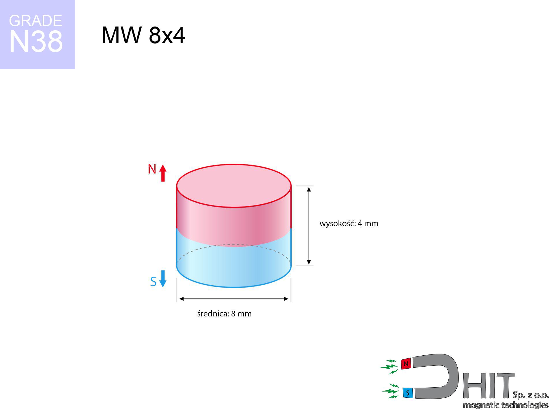
MW 8x4 / N38 - cylindrical magnet
cylindrical magnet
Catalog no 010104
GTIN/EAN: 5906301811039
Diameter Ø
8 mm [±0,1 mm]
Height
4 mm [±0,1 mm]
Weight
1.51 g
Magnetization Direction
↑ axial
Load capacity
2.04 kg / 20.00 N
Magnetic Induction
437.78 mT / 4378 Gs
Coating
[NiCuNi] Nickel
0.701 ZŁ with VAT / pcs + price for transport
0.570 ZŁ net + 23% VAT / pcs
bulk discounts:
Need more?Engineering report for this magnet
Full PDF analysis: pull and shear force, effect of distance, temperature and plate thickness, safety distances and the demagnetization curve.
Pick up the phone and ask
+48 22 499 98 98
otherwise get in touch through
form
the contact section.
Strength and shape of magnets can be estimated on our
our magnetic calculator.
Orders placed before 14:00 will be shipped the same business day.
Technical parameters of the product - MW 8x4 / N38 - cylindrical magnet
Specification / characteristics - MW 8x4 / N38 - cylindrical magnet
| properties | values |
|---|---|
| Cat. no. | 010104 |
| GTIN/EAN | 5906301811039 |
| Production/Distribution | Dhit sp. z o.o. |
| Country of origin | Poland / China / Germany |
| Customs code | 85059029 |
| Diameter Ø | 8 mm [±0,1 mm] |
| Height | 4 mm [±0,1 mm] |
| Weight | 1.51 g |
| Magnetization Direction | ↑ axial |
| Load capacity ~ ? | 2.04 kg / 20.00 N |
| Magnetic Induction ~ ? | 437.78 mT / 4378 Gs |
| Coating | [NiCuNi] Nickel |
| Manufacturing Tolerance | ±0.1 mm |
Magnetic properties of material N38
| properties | values | units |
|---|---|---|
| remenance Br [min. - max.] ? | 12.2-12.6 | kGs |
| remenance Br [min. - max.] ? | 1220-1260 | mT |
| coercivity bHc ? | 10.8-11.5 | kOe |
| coercivity bHc ? | 860-915 | kA/m |
| actual internal force iHc | ≥ 12 | kOe |
| actual internal force iHc | ≥ 955 | kA/m |
| energy density [min. - max.] ? | 36-38 | BH max MGOe |
| energy density [min. - max.] ? | 287-303 | BH max KJ/m |
| max. temperature ? | ≤ 80 | °C |
Physical properties of sintered neodymium magnets Nd2Fe14B at 20°C
| properties | values | units |
|---|---|---|
| Vickers hardness | ≥550 | Hv |
| Density | ≥7.4 | g/cm3 |
| Curie Temperature TC | 312 - 380 | °C |
| Curie Temperature TF | 593 - 716 | °F |
| Specific resistance | 150 | μΩ⋅cm |
| Bending strength | 250 | MPa |
| Compressive strength | 1000~1100 | MPa |
| Thermal expansion parallel (∥) to orientation (M) | (3-4) x 10-6 | °C-1 |
| Thermal expansion perpendicular (⊥) to orientation (M) | -(1-3) x 10-6 | °C-1 |
| Young's modulus | 1.7 x 10⁴ | kg/mm² |
Engineering analysis of the assembly - technical parameters
Presented values are the outcome of a mathematical analysis. Values rely on algorithms for the material Nd2Fe14B. Actual parameters might slightly differ. Treat these calculations as a preliminary roadmap for designers.
Table 1: Static force (pull vs gap) - power drop
MW 8x4 / N38
| Distance (mm) | Induction (Gauss) / mT | Pull Force (kg/lbs/g/N) | Risk Status |
|---|---|---|---|
| 0 mm |
4374 Gs
437.4 mT
|
2.04 kg / 4.50 lbs
2040.0 g / 20.0 N
|
warning |
| 1 mm |
3338 Gs
333.8 mT
|
1.19 kg / 2.62 lbs
1187.8 g / 11.7 N
|
weak grip |
| 2 mm |
2386 Gs
238.6 mT
|
0.61 kg / 1.34 lbs
607.0 g / 6.0 N
|
weak grip |
| 3 mm |
1663 Gs
166.3 mT
|
0.29 kg / 0.65 lbs
294.9 g / 2.9 N
|
weak grip |
| 5 mm |
824 Gs
82.4 mT
|
0.07 kg / 0.16 lbs
72.4 g / 0.7 N
|
weak grip |
| 10 mm |
205 Gs
20.5 mT
|
0.00 kg / 0.01 lbs
4.5 g / 0.0 N
|
weak grip |
| 15 mm |
76 Gs
7.6 mT
|
0.00 kg / 0.00 lbs
0.6 g / 0.0 N
|
weak grip |
| 20 mm |
36 Gs
3.6 mT
|
0.00 kg / 0.00 lbs
0.1 g / 0.0 N
|
weak grip |
| 30 mm |
12 Gs
1.2 mT
|
0.00 kg / 0.00 lbs
0.0 g / 0.0 N
|
weak grip |
| 50 mm |
3 Gs
0.3 mT
|
0.00 kg / 0.00 lbs
0.0 g / 0.0 N
|
weak grip |
Table 2: Vertical force (vertical surface)
MW 8x4 / N38
| Distance (mm) | Friction coefficient | Pull Force (kg/lbs/g/N) |
|---|---|---|
| 0 mm | Stal (~0.2) |
0.41 kg / 0.90 lbs
408.0 g / 4.0 N
|
| 1 mm | Stal (~0.2) |
0.24 kg / 0.52 lbs
238.0 g / 2.3 N
|
| 2 mm | Stal (~0.2) |
0.12 kg / 0.27 lbs
122.0 g / 1.2 N
|
| 3 mm | Stal (~0.2) |
0.06 kg / 0.13 lbs
58.0 g / 0.6 N
|
| 5 mm | Stal (~0.2) |
0.01 kg / 0.03 lbs
14.0 g / 0.1 N
|
| 10 mm | Stal (~0.2) |
0.00 kg / 0.00 lbs
0.0 g / 0.0 N
|
| 15 mm | Stal (~0.2) |
0.00 kg / 0.00 lbs
0.0 g / 0.0 N
|
| 20 mm | Stal (~0.2) |
0.00 kg / 0.00 lbs
0.0 g / 0.0 N
|
| 30 mm | Stal (~0.2) |
0.00 kg / 0.00 lbs
0.0 g / 0.0 N
|
| 50 mm | Stal (~0.2) |
0.00 kg / 0.00 lbs
0.0 g / 0.0 N
|
Table 3: Wall mounting (sliding) - behavior on slippery surfaces
MW 8x4 / N38
| Surface type | Friction coefficient / % Mocy | Max load (kg/lbs/g/N) |
|---|---|---|
| Raw steel |
µ = 0.3
30% Nominalnej Siły
|
0.61 kg / 1.35 lbs
612.0 g / 6.0 N
|
| Painted steel (standard) |
µ = 0.2
20% Nominalnej Siły
|
0.41 kg / 0.90 lbs
408.0 g / 4.0 N
|
| Oily/slippery steel |
µ = 0.1
10% Nominalnej Siły
|
0.20 kg / 0.45 lbs
204.0 g / 2.0 N
|
| Magnet with anti-slip rubber |
µ = 0.5
50% Nominalnej Siły
|
1.02 kg / 2.25 lbs
1020.0 g / 10.0 N
|
Table 4: Material efficiency (saturation) - sheet metal selection
MW 8x4 / N38
| Steel thickness (mm) | % power | Real pull force (kg/lbs/g/N) |
|---|---|---|
| 0.5 mm |
|
0.20 kg / 0.45 lbs
204.0 g / 2.0 N
|
| 1 mm |
|
0.51 kg / 1.12 lbs
510.0 g / 5.0 N
|
| 2 mm |
|
1.02 kg / 2.25 lbs
1020.0 g / 10.0 N
|
| 3 mm |
|
1.53 kg / 3.37 lbs
1530.0 g / 15.0 N
|
| 5 mm |
|
2.04 kg / 4.50 lbs
2040.0 g / 20.0 N
|
| 10 mm |
|
2.04 kg / 4.50 lbs
2040.0 g / 20.0 N
|
| 11 mm |
|
2.04 kg / 4.50 lbs
2040.0 g / 20.0 N
|
| 12 mm |
|
2.04 kg / 4.50 lbs
2040.0 g / 20.0 N
|
Table 5: Thermal resistance (material behavior) - power drop
MW 8x4 / N38
| Ambient temp. (°C) | Power loss | Remaining pull (kg/lbs/g/N) | Status |
|---|---|---|---|
| 20 °C | 0.0% |
2.04 kg / 4.50 lbs
2040.0 g / 20.0 N
|
OK |
| 40 °C | -2.2% |
2.00 kg / 4.40 lbs
1995.1 g / 19.6 N
|
OK |
| 60 °C | -4.4% |
1.95 kg / 4.30 lbs
1950.2 g / 19.1 N
|
|
| 80 °C | -6.6% |
1.91 kg / 4.20 lbs
1905.4 g / 18.7 N
|
|
| 100 °C | -28.8% |
1.45 kg / 3.20 lbs
1452.5 g / 14.2 N
|
Table 6: Two magnets (attraction) - field collision
MW 8x4 / N38
| Gap (mm) | Attraction (kg/lbs) (N-S) | Shear Force (kg/lbs/g/N) | Repulsion (kg/lbs) (N-N) |
|---|---|---|---|
| 0 mm |
5.93 kg / 13.07 lbs
5 531 Gs
|
0.89 kg / 1.96 lbs
889 g / 8.7 N
|
N/A |
| 1 mm |
4.63 kg / 10.21 lbs
7 730 Gs
|
0.69 kg / 1.53 lbs
694 g / 6.8 N
|
4.17 kg / 9.18 lbs
~0 Gs
|
| 2 mm |
3.45 kg / 7.61 lbs
6 675 Gs
|
0.52 kg / 1.14 lbs
518 g / 5.1 N
|
3.11 kg / 6.85 lbs
~0 Gs
|
| 3 mm |
2.49 kg / 5.50 lbs
5 674 Gs
|
0.37 kg / 0.82 lbs
374 g / 3.7 N
|
2.25 kg / 4.95 lbs
~0 Gs
|
| 5 mm |
1.23 kg / 2.72 lbs
3 989 Gs
|
0.18 kg / 0.41 lbs
185 g / 1.8 N
|
1.11 kg / 2.45 lbs
~0 Gs
|
| 10 mm |
0.21 kg / 0.46 lbs
1 648 Gs
|
0.03 kg / 0.07 lbs
32 g / 0.3 N
|
0.19 kg / 0.42 lbs
~0 Gs
|
| 20 mm |
0.01 kg / 0.03 lbs
410 Gs
|
0.00 kg / 0.00 lbs
2 g / 0.0 N
|
0.01 kg / 0.03 lbs
~0 Gs
|
| 50 mm |
0.00 kg / 0.00 lbs
39 Gs
|
0.00 kg / 0.00 lbs
0 g / 0.0 N
|
0.00 kg / 0.00 lbs
~0 Gs
|
| 60 mm |
0.00 kg / 0.00 lbs
24 Gs
|
0.00 kg / 0.00 lbs
0 g / 0.0 N
|
0.00 kg / 0.00 lbs
~0 Gs
|
| 70 mm |
0.00 kg / 0.00 lbs
15 Gs
|
0.00 kg / 0.00 lbs
0 g / 0.0 N
|
0.00 kg / 0.00 lbs
~0 Gs
|
| 80 mm |
0.00 kg / 0.00 lbs
11 Gs
|
0.00 kg / 0.00 lbs
0 g / 0.0 N
|
0.00 kg / 0.00 lbs
~0 Gs
|
| 90 mm |
0.00 kg / 0.00 lbs
8 Gs
|
0.00 kg / 0.00 lbs
0 g / 0.0 N
|
0.00 kg / 0.00 lbs
~0 Gs
|
| 100 mm |
0.00 kg / 0.00 lbs
6 Gs
|
0.00 kg / 0.00 lbs
0 g / 0.0 N
|
0.00 kg / 0.00 lbs
~0 Gs
|
Table 7: Safety (HSE) (electronics) - precautionary measures
MW 8x4 / N38
| Object / Device | Limit (Gauss) / mT | Safe distance |
|---|---|---|
| Pacemaker | 5 Gs (0.5 mT) | 4.5 cm |
| Hearing aid | 10 Gs (1.0 mT) | 3.5 cm |
| Timepiece | 20 Gs (2.0 mT) | 2.5 cm |
| Phone / Smartphone | 40 Gs (4.0 mT) | 2.0 cm |
| Remote | 50 Gs (5.0 mT) | 2.0 cm |
| Payment card | 400 Gs (40.0 mT) | 1.0 cm |
| HDD hard drive | 600 Gs (60.0 mT) | 1.0 cm |
Table 8: Impact energy (cracking risk) - warning
MW 8x4 / N38
| Start from (mm) | Speed (km/h) | Energy (J) | Predicted outcome |
|---|---|---|---|
| 10 mm |
37.12 km/h
(10.31 m/s)
|
0.08 J | |
| 30 mm |
64.21 km/h
(17.83 m/s)
|
0.24 J | |
| 50 mm |
82.89 km/h
(23.02 m/s)
|
0.40 J | |
| 100 mm |
117.22 km/h
(32.56 m/s)
|
0.80 J |
Table 9: Corrosion resistance
MW 8x4 / N38
| Technical parameter | Value / Description |
|---|---|
| Coating type | [NiCuNi] Nickel |
| Layer structure | Nickel - Copper - Nickel |
| Layer thickness | 10-20 µm |
| Salt spray test (SST) ? | 24 h |
| Recommended environment | Indoors only (dry) |
Table 10: Electrical data (Flux)
MW 8x4 / N38
| Parameter | Value | SI Unit / Description |
|---|---|---|
| Magnetic Flux | 2 233 Mx | 22.3 µWb |
| Pc Coefficient | 0.59 | Low (Flat) |
Table 11: Physics of underwater searching
MW 8x4 / N38
| Environment | Effective steel pull | Effect |
|---|---|---|
| Air (land) | 2.04 kg | Standard |
| Water (riverbed) |
2.34 kg
(+0.30 kg buoyancy gain)
|
+14.5% |
1. Wall mount (shear)
*Caution: On a vertical wall, the magnet holds merely approx. 20-30% of its perpendicular strength.
2. Steel saturation
*Thin metal sheet (e.g. 0.5mm PC case) severely limits the holding force.
3. Thermal stability
*For standard magnets, the safety limit is 80°C.
4. Demagnetization curve and operating point (B-H)
chart generated for the permeance coefficient Pc (Permeance Coefficient) = 0.59
This simulation demonstrates the magnetic stability of the selected magnet under specific geometric conditions. The solid red line represents the demagnetization curve (material potential), while the dashed blue line is the load line based on the magnet's geometry. The Pc (Permeance Coefficient), also known as the load line slope, is a dimensionless value that describes the relationship between the magnet's shape and its magnetic stability. The intersection of these two lines (the black dot) is the operating point — it determines the actual magnetic flux density generated by the magnet in this specific configuration. A higher Pc value means the magnet is more 'slender' (tall relative to its area), resulting in a higher operating point and better resistance to irreversible demagnetization caused by external fields or temperature. A value of 0.42 is relatively low (typical for flat magnets), meaning the operating point is closer to the 'knee' of the curve — caution is advised when operating at temperatures near the maximum limit to avoid strength loss.
Material specification
| iron (Fe) | 64% – 68% |
| neodymium (Nd) | 29% – 32% |
| boron (B) | 1.1% – 1.2% |
| dysprosium (Dy) | 0.5% – 2.0% |
| coating (Ni-Cu-Ni) | < 0.05% |
Sustainability
| recyclability (EoL) | 100% |
| recycled raw materials | ~10% (pre-cons) |
| carbon footprint | low / zredukowany |
| waste code (EWC) | 16 02 16 |
Check out also products


Pros as well as cons of rare earth magnets.
Strengths
- They retain full power for around ten years – the loss is just ~1% (in theory),
- Magnets perfectly protect themselves against demagnetization caused by ambient magnetic noise,
- The use of an refined coating of noble metals (nickel, gold, silver) causes the element to look better,
- The surface of neodymium magnets generates a strong magnetic field – this is one of their assets,
- Through (adequate) combination of ingredients, they can achieve high thermal strength, enabling action at temperatures approaching 230°C and above...
- Thanks to modularity in constructing and the ability to customize to specific needs,
- Huge importance in high-tech industry – they are used in data components, electric motors, precision medical tools, as well as technologically advanced constructions.
- Compactness – despite small sizes they generate large force, making them ideal for precision applications
Cons
- Brittleness is one of their disadvantages. Upon intense impact they can break. We advise keeping them in a special holder, which not only protects them against impacts but also increases their durability
- When exposed to high temperature, neodymium magnets experience a drop in force. Often, when the temperature exceeds 80°C, their strength decreases (depending on the size, as well as shape of the magnet). For those who need magnets for extreme conditions, we offer [AH] versions withstanding up to 230°C
- Magnets exposed to a humid environment can rust. Therefore during using outdoors, we suggest using waterproof magnets made of rubber, plastic or other material protecting against moisture
- We suggest a housing - magnetic mount, due to difficulties in realizing threads inside the magnet and complex forms.
- Potential hazard resulting from small fragments of magnets can be dangerous, if swallowed, which gains importance in the context of child safety. Furthermore, small elements of these devices can complicate diagnosis medical in case of swallowing.
- With large orders the cost of neodymium magnets is a challenge,
Pull force analysis
Highest magnetic holding force – what it depends on?
- using a sheet made of high-permeability steel, serving as a circuit closing element
- whose thickness reaches at least 10 mm
- with a surface free of scratches
- without any clearance between the magnet and steel
- during detachment in a direction perpendicular to the plane
- at room temperature
What influences lifting capacity in practice
- Distance (between the magnet and the plate), since even a tiny clearance (e.g. 0.5 mm) can cause a reduction in force by up to 50% (this also applies to paint, corrosion or dirt).
- Angle of force application – maximum parameter is available only during pulling at a 90° angle. The force required to slide of the magnet along the surface is usually many times smaller (approx. 1/5 of the lifting capacity).
- Element thickness – to utilize 100% power, the steel must be sufficiently thick. Thin sheet restricts the attraction force (the magnet "punches through" it).
- Material type – ideal substrate is high-permeability steel. Stainless steels may attract less.
- Surface condition – ground elements ensure maximum contact, which improves field saturation. Rough surfaces reduce efficiency.
- Thermal factor – high temperature weakens pulling force. Exceeding the limit temperature can permanently demagnetize the magnet.
Lifting capacity testing was conducted on plates with a smooth surface of suitable thickness, under a perpendicular pulling force, whereas under attempts to slide the magnet the load capacity is reduced by as much as 75%. Moreover, even a small distance between the magnet’s surface and the plate lowers the load capacity.
Warnings
Demagnetization risk
Standard neodymium magnets (grade N) lose power when the temperature exceeds 80°C. Damage is permanent.
Electronic devices
Do not bring magnets close to a wallet, computer, or TV. The magnetism can destroy these devices and wipe information from cards.
Combustion hazard
Machining of neodymium magnets poses a fire hazard. Magnetic powder reacts violently with oxygen and is hard to extinguish.
Risk of cracking
NdFeB magnets are sintered ceramics, meaning they are prone to chipping. Clashing of two magnets will cause them breaking into small pieces.
Danger to pacemakers
Life threat: Neodymium magnets can deactivate pacemakers and defibrillators. Stay away if you have medical devices.
Adults only
Strictly keep magnets away from children. Ingestion danger is high, and the effects of magnets connecting inside the body are fatal.
Respect the power
Before starting, read the rules. Uncontrolled attraction can break the magnet or hurt your hand. Think ahead.
Metal Allergy
Warning for allergy sufferers: The Ni-Cu-Ni coating consists of nickel. If redness happens, cease working with magnets and wear gloves.
Crushing risk
Big blocks can break fingers in a fraction of a second. Never place your hand between two strong magnets.
Phone sensors
A powerful magnetic field interferes with the operation of magnetometers in phones and GPS navigation. Maintain magnets near a device to avoid breaking the sensors.
Tabela kosztu i czasu dostawy
Płatność przed wysyłką:

GLS kurier
Przesyłka będzie u Ciebie za 2-3 dni
14.99 ZŁ

InPost Paczkomaty 24/7
Przesyłka będzie u Ciebie za 1-2 dni
12.30 ZŁ
Płatność przy odbiorze (pobranie):
GLS kurier
Przesyłka będzie u Ciebie za 1-2 dni
23.00 ZŁ
Rate the product
Your rating