
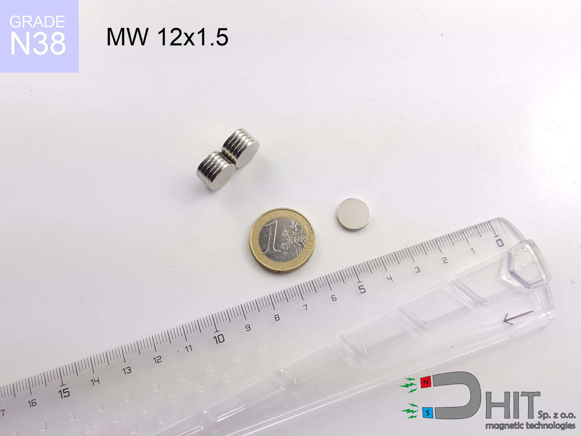
MW 12x1.5 / N38 - cylindrical magnet
cylindrical magnet
Catalog no 010442
GTIN/EAN: 5906301811114
Diameter Ø
12 mm [±0,1 mm]
Height
1.5 mm [±0,1 mm]
Weight
1.27 g
Magnetization Direction
↑ axial
Load capacity
0.87 kg / 8.51 N
Magnetic Induction
150.32 mT / 1503 Gs
Coating
[NiCuNi] Nickel
0.431 ZŁ with VAT / pcs + price for transport
0.350 ZŁ net + 23% VAT / pcs
bulk discounts:
Need more?
Pick up the phone and ask
+48 22 499 98 98
otherwise contact us using
request form
through our site.
Force and shape of neodymium magnets can be checked on our
modular calculator.
Same-day shipping for orders placed before 14:00.
Detailed specification - MW 12x1.5 / N38 - cylindrical magnet
Specification / characteristics - MW 12x1.5 / N38 - cylindrical magnet
| properties | values |
|---|---|
| Cat. no. | 010442 |
| GTIN/EAN | 5906301811114 |
| Production/Distribution | Dhit sp. z o.o. |
| Country of origin | Poland / China / Germany |
| Customs code | 85059029 |
| Diameter Ø | 12 mm [±0,1 mm] |
| Height | 1.5 mm [±0,1 mm] |
| Weight | 1.27 g |
| Magnetization Direction | ↑ axial |
| Load capacity ~ ? | 0.87 kg / 8.51 N |
| Magnetic Induction ~ ? | 150.32 mT / 1503 Gs |
| Coating | [NiCuNi] Nickel |
| Manufacturing Tolerance | ±0.1 mm |
Magnetic properties of material N38
| properties | values | units |
|---|---|---|
| remenance Br [min. - max.] ? | 12.2-12.6 | kGs |
| remenance Br [min. - max.] ? | 1220-1260 | mT |
| coercivity bHc ? | 10.8-11.5 | kOe |
| coercivity bHc ? | 860-915 | kA/m |
| actual internal force iHc | ≥ 12 | kOe |
| actual internal force iHc | ≥ 955 | kA/m |
| energy density [min. - max.] ? | 36-38 | BH max MGOe |
| energy density [min. - max.] ? | 287-303 | BH max KJ/m |
| max. temperature ? | ≤ 80 | °C |
Physical properties of sintered neodymium magnets Nd2Fe14B at 20°C
| properties | values | units |
|---|---|---|
| Vickers hardness | ≥550 | Hv |
| Density | ≥7.4 | g/cm3 |
| Curie Temperature TC | 312 - 380 | °C |
| Curie Temperature TF | 593 - 716 | °F |
| Specific resistance | 150 | μΩ⋅cm |
| Bending strength | 250 | MPa |
| Compressive strength | 1000~1100 | MPa |
| Thermal expansion parallel (∥) to orientation (M) | (3-4) x 10-6 | °C-1 |
| Thermal expansion perpendicular (⊥) to orientation (M) | -(1-3) x 10-6 | °C-1 |
| Young's modulus | 1.7 x 10⁴ | kg/mm² |
Engineering modeling of the magnet - technical parameters
The following information are the direct effect of a mathematical simulation. Results rely on algorithms for the material Nd2Fe14B. Actual conditions might slightly differ. Use these data as a supplementary guide during assembly planning.
Table 1: Static pull force (force vs distance) - interaction chart
MW 12x1.5 / N38
| Distance (mm) | Induction (Gauss) / mT | Pull Force (kg/lbs/g/N) | Risk Status |
|---|---|---|---|
| 0 mm |
1503 Gs
150.3 mT
|
0.87 kg / 1.92 lbs
870.0 g / 8.5 N
|
safe |
| 1 mm |
1365 Gs
136.5 mT
|
0.72 kg / 1.58 lbs
718.1 g / 7.0 N
|
safe |
| 2 mm |
1163 Gs
116.3 mT
|
0.52 kg / 1.15 lbs
521.4 g / 5.1 N
|
safe |
| 3 mm |
947 Gs
94.7 mT
|
0.35 kg / 0.76 lbs
345.7 g / 3.4 N
|
safe |
| 5 mm |
587 Gs
58.7 mT
|
0.13 kg / 0.29 lbs
132.6 g / 1.3 N
|
safe |
| 10 mm |
180 Gs
18.0 mT
|
0.01 kg / 0.03 lbs
12.5 g / 0.1 N
|
safe |
| 15 mm |
70 Gs
7.0 mT
|
0.00 kg / 0.00 lbs
1.9 g / 0.0 N
|
safe |
| 20 mm |
33 Gs
3.3 mT
|
0.00 kg / 0.00 lbs
0.4 g / 0.0 N
|
safe |
| 30 mm |
11 Gs
1.1 mT
|
0.00 kg / 0.00 lbs
0.0 g / 0.0 N
|
safe |
| 50 mm |
3 Gs
0.3 mT
|
0.00 kg / 0.00 lbs
0.0 g / 0.0 N
|
safe |
Table 2: Vertical capacity (wall)
MW 12x1.5 / N38
| Distance (mm) | Friction coefficient | Pull Force (kg/lbs/g/N) |
|---|---|---|
| 0 mm | Stal (~0.2) |
0.17 kg / 0.38 lbs
174.0 g / 1.7 N
|
| 1 mm | Stal (~0.2) |
0.14 kg / 0.32 lbs
144.0 g / 1.4 N
|
| 2 mm | Stal (~0.2) |
0.10 kg / 0.23 lbs
104.0 g / 1.0 N
|
| 3 mm | Stal (~0.2) |
0.07 kg / 0.15 lbs
70.0 g / 0.7 N
|
| 5 mm | Stal (~0.2) |
0.03 kg / 0.06 lbs
26.0 g / 0.3 N
|
| 10 mm | Stal (~0.2) |
0.00 kg / 0.00 lbs
2.0 g / 0.0 N
|
| 15 mm | Stal (~0.2) |
0.00 kg / 0.00 lbs
0.0 g / 0.0 N
|
| 20 mm | Stal (~0.2) |
0.00 kg / 0.00 lbs
0.0 g / 0.0 N
|
| 30 mm | Stal (~0.2) |
0.00 kg / 0.00 lbs
0.0 g / 0.0 N
|
| 50 mm | Stal (~0.2) |
0.00 kg / 0.00 lbs
0.0 g / 0.0 N
|
Table 3: Wall mounting (sliding) - vertical pull
MW 12x1.5 / N38
| Surface type | Friction coefficient / % Mocy | Max load (kg/lbs/g/N) |
|---|---|---|
| Raw steel |
µ = 0.3
30% Nominalnej Siły
|
0.26 kg / 0.58 lbs
261.0 g / 2.6 N
|
| Painted steel (standard) |
µ = 0.2
20% Nominalnej Siły
|
0.17 kg / 0.38 lbs
174.0 g / 1.7 N
|
| Oily/slippery steel |
µ = 0.1
10% Nominalnej Siły
|
0.09 kg / 0.19 lbs
87.0 g / 0.9 N
|
| Magnet with anti-slip rubber |
µ = 0.5
50% Nominalnej Siły
|
0.44 kg / 0.96 lbs
435.0 g / 4.3 N
|
Table 4: Material efficiency (substrate influence) - sheet metal selection
MW 12x1.5 / N38
| Steel thickness (mm) | % power | Real pull force (kg/lbs/g/N) |
|---|---|---|
| 0.5 mm |
|
0.09 kg / 0.19 lbs
87.0 g / 0.9 N
|
| 1 mm |
|
0.22 kg / 0.48 lbs
217.5 g / 2.1 N
|
| 2 mm |
|
0.44 kg / 0.96 lbs
435.0 g / 4.3 N
|
| 3 mm |
|
0.65 kg / 1.44 lbs
652.5 g / 6.4 N
|
| 5 mm |
|
0.87 kg / 1.92 lbs
870.0 g / 8.5 N
|
| 10 mm |
|
0.87 kg / 1.92 lbs
870.0 g / 8.5 N
|
| 11 mm |
|
0.87 kg / 1.92 lbs
870.0 g / 8.5 N
|
| 12 mm |
|
0.87 kg / 1.92 lbs
870.0 g / 8.5 N
|
Table 5: Working in heat (material behavior) - thermal limit
MW 12x1.5 / N38
| Ambient temp. (°C) | Power loss | Remaining pull (kg/lbs/g/N) | Status |
|---|---|---|---|
| 20 °C | 0.0% |
0.87 kg / 1.92 lbs
870.0 g / 8.5 N
|
OK |
| 40 °C | -2.2% |
0.85 kg / 1.88 lbs
850.9 g / 8.3 N
|
OK |
| 60 °C | -4.4% |
0.83 kg / 1.83 lbs
831.7 g / 8.2 N
|
|
| 80 °C | -6.6% |
0.81 kg / 1.79 lbs
812.6 g / 8.0 N
|
|
| 100 °C | -28.8% |
0.62 kg / 1.37 lbs
619.4 g / 6.1 N
|
Table 6: Two magnets (attraction) - field collision
MW 12x1.5 / N38
| Gap (mm) | Attraction (kg/lbs) (N-S) | Sliding Force (kg/lbs/g/N) | Repulsion (kg/lbs) (N-N) |
|---|---|---|---|
| 0 mm |
1.57 kg / 3.47 lbs
2 770 Gs
|
0.24 kg / 0.52 lbs
236 g / 2.3 N
|
N/A |
| 1 mm |
1.46 kg / 3.21 lbs
2 891 Gs
|
0.22 kg / 0.48 lbs
219 g / 2.1 N
|
1.31 kg / 2.89 lbs
~0 Gs
|
| 2 mm |
1.30 kg / 2.87 lbs
2 731 Gs
|
0.19 kg / 0.43 lbs
195 g / 1.9 N
|
1.17 kg / 2.58 lbs
~0 Gs
|
| 3 mm |
1.12 kg / 2.48 lbs
2 538 Gs
|
0.17 kg / 0.37 lbs
168 g / 1.7 N
|
1.01 kg / 2.23 lbs
~0 Gs
|
| 5 mm |
0.78 kg / 1.71 lbs
2 109 Gs
|
0.12 kg / 0.26 lbs
116 g / 1.1 N
|
0.70 kg / 1.54 lbs
~0 Gs
|
| 10 mm |
0.24 kg / 0.53 lbs
1 173 Gs
|
0.04 kg / 0.08 lbs
36 g / 0.4 N
|
0.22 kg / 0.48 lbs
~0 Gs
|
| 20 mm |
0.02 kg / 0.05 lbs
361 Gs
|
0.00 kg / 0.01 lbs
3 g / 0.0 N
|
0.02 kg / 0.05 lbs
~0 Gs
|
| 50 mm |
0.00 kg / 0.00 lbs
36 Gs
|
0.00 kg / 0.00 lbs
0 g / 0.0 N
|
0.00 kg / 0.00 lbs
~0 Gs
|
| 60 mm |
0.00 kg / 0.00 lbs
22 Gs
|
0.00 kg / 0.00 lbs
0 g / 0.0 N
|
0.00 kg / 0.00 lbs
~0 Gs
|
| 70 mm |
0.00 kg / 0.00 lbs
14 Gs
|
0.00 kg / 0.00 lbs
0 g / 0.0 N
|
0.00 kg / 0.00 lbs
~0 Gs
|
| 80 mm |
0.00 kg / 0.00 lbs
10 Gs
|
0.00 kg / 0.00 lbs
0 g / 0.0 N
|
0.00 kg / 0.00 lbs
~0 Gs
|
| 90 mm |
0.00 kg / 0.00 lbs
7 Gs
|
0.00 kg / 0.00 lbs
0 g / 0.0 N
|
0.00 kg / 0.00 lbs
~0 Gs
|
| 100 mm |
0.00 kg / 0.00 lbs
5 Gs
|
0.00 kg / 0.00 lbs
0 g / 0.0 N
|
0.00 kg / 0.00 lbs
~0 Gs
|
Table 7: Safety (HSE) (implants) - precautionary measures
MW 12x1.5 / N38
| Object / Device | Limit (Gauss) / mT | Safe distance |
|---|---|---|
| Pacemaker | 5 Gs (0.5 mT) | 4.0 cm |
| Hearing aid | 10 Gs (1.0 mT) | 3.5 cm |
| Mechanical watch | 20 Gs (2.0 mT) | 2.5 cm |
| Phone / Smartphone | 40 Gs (4.0 mT) | 2.0 cm |
| Remote | 50 Gs (5.0 mT) | 2.0 cm |
| Payment card | 400 Gs (40.0 mT) | 1.0 cm |
| HDD hard drive | 600 Gs (60.0 mT) | 0.5 cm |
Table 8: Dynamics (kinetic energy) - warning
MW 12x1.5 / N38
| Start from (mm) | Speed (km/h) | Energy (J) | Predicted outcome |
|---|---|---|---|
| 10 mm |
26.63 km/h
(7.40 m/s)
|
0.03 J | |
| 30 mm |
45.72 km/h
(12.70 m/s)
|
0.10 J | |
| 50 mm |
59.02 km/h
(16.40 m/s)
|
0.17 J | |
| 100 mm |
83.47 km/h
(23.19 m/s)
|
0.34 J |
Table 9: Corrosion resistance
MW 12x1.5 / N38
| Technical parameter | Value / Description |
|---|---|
| Coating type | [NiCuNi] Nickel |
| Layer structure | Nickel - Copper - Nickel |
| Layer thickness | 10-20 µm |
| Salt spray test (SST) ? | 24 h |
| Recommended environment | Indoors only (dry) |
Table 10: Electrical data (Flux)
MW 12x1.5 / N38
| Parameter | Value | SI Unit / Description |
|---|---|---|
| Magnetic Flux | 2 159 Mx | 21.6 µWb |
| Pc Coefficient | 0.19 | Low (Flat) |
Table 11: Submerged application
MW 12x1.5 / N38
| Environment | Effective steel pull | Effect |
|---|---|---|
| Air (land) | 0.87 kg | Standard |
| Water (riverbed) |
1.00 kg
(+0.13 kg buoyancy gain)
|
+14.5% |
1. Vertical hold
*Warning: On a vertical surface, the magnet retains only a fraction of its max power.
2. Efficiency vs thickness
*Thin steel (e.g. 0.5mm PC case) drastically reduces the holding force.
3. Thermal stability
*For standard magnets, the safety limit is 80°C.
4. Demagnetization curve and operating point (B-H)
chart generated for the permeance coefficient Pc (Permeance Coefficient) = 0.19
This simulation demonstrates the magnetic stability of the selected magnet under specific geometric conditions. The solid red line represents the demagnetization curve (material potential), while the dashed blue line is the load line based on the magnet's geometry. The Pc (Permeance Coefficient), also known as the load line slope, is a dimensionless value that describes the relationship between the magnet's shape and its magnetic stability. The intersection of these two lines (the black dot) is the operating point — it determines the actual magnetic flux density generated by the magnet in this specific configuration. A higher Pc value means the magnet is more 'slender' (tall relative to its area), resulting in a higher operating point and better resistance to irreversible demagnetization caused by external fields or temperature. A value of 0.42 is relatively low (typical for flat magnets), meaning the operating point is closer to the 'knee' of the curve — caution is advised when operating at temperatures near the maximum limit to avoid strength loss.
Chemical composition
| iron (Fe) | 64% – 68% |
| neodymium (Nd) | 29% – 32% |
| boron (B) | 1.1% – 1.2% |
| dysprosium (Dy) | 0.5% – 2.0% |
| coating (Ni-Cu-Ni) | < 0.05% |
Ecology and recycling (GPSR)
| recyclability (EoL) | 100% |
| recycled raw materials | ~10% (pre-cons) |
| carbon footprint | low / zredukowany |
| waste code (EWC) | 16 02 16 |
Other products

![UMP 94x40 [3xM10] GW F550 Silver Black / N52 - search holder](https://cdn3.dhit.pl/graphics/products/ump-94x40-3xm10-gw-f550-fad.jpg "UMP 94x40 [3xM10] GW F550 Silver Black / N52 - search holder")


Strengths as well as weaknesses of rare earth magnets.
Pros
- They virtually do not lose power, because even after ten years the decline in efficiency is only ~1% (according to literature),
- Neodymium magnets prove to be exceptionally resistant to magnetic field loss caused by magnetic disturbances,
- Thanks to the metallic finish, the plating of Ni-Cu-Ni, gold, or silver-plated gives an modern appearance,
- Magnets have very high magnetic induction on the active area,
- Thanks to resistance to high temperature, they are able to function (depending on the form) even at temperatures up to 230°C and higher...
- Thanks to freedom in forming and the ability to customize to specific needs,
- Key role in high-tech industry – they are used in magnetic memories, motor assemblies, medical devices, and multitasking production systems.
- Compactness – despite small sizes they provide effective action, making them ideal for precision applications
Disadvantages
- At very strong impacts they can crack, therefore we advise placing them in strong housings. A metal housing provides additional protection against damage and increases the magnet's durability.
- We warn that neodymium magnets can reduce their strength at high temperatures. To prevent this, we recommend our specialized [AH] magnets, which work effectively even at 230°C.
- Due to the susceptibility of magnets to corrosion in a humid environment, we suggest using waterproof magnets made of rubber, plastic or other material stable to moisture, in case of application outdoors
- We recommend a housing - magnetic mechanism, due to difficulties in creating threads inside the magnet and complex forms.
- Possible danger related to microscopic parts of magnets pose a threat, when accidentally swallowed, which gains importance in the context of child health protection. It is also worth noting that small elements of these devices are able to complicate diagnosis medical in case of swallowing.
- Higher cost of purchase is one of the disadvantages compared to ceramic magnets, especially in budget applications
Holding force characteristics
Maximum magnetic pulling force – what affects it?
- with the contact of a yoke made of low-carbon steel, ensuring maximum field concentration
- whose thickness reaches at least 10 mm
- with a plane perfectly flat
- with direct contact (no paint)
- for force acting at a right angle (in the magnet axis)
- in neutral thermal conditions
Determinants of practical lifting force of a magnet
- Distance – existence of foreign body (rust, tape, gap) interrupts the magnetic circuit, which reduces capacity steeply (even by 50% at 0.5 mm).
- Loading method – declared lifting capacity refers to detachment vertically. When applying parallel force, the magnet exhibits much less (often approx. 20-30% of maximum force).
- Steel thickness – too thin plate causes magnetic saturation, causing part of the flux to be wasted into the air.
- Steel grade – ideal substrate is high-permeability steel. Cast iron may have worse magnetic properties.
- Surface structure – the more even the plate, the better the adhesion and stronger the hold. Unevenness creates an air distance.
- Operating temperature – neodymium magnets have a sensitivity to temperature. When it is hot they are weaker, and at low temperatures they can be stronger (up to a certain limit).
Lifting capacity was determined by applying a steel plate with a smooth surface of suitable thickness (min. 20 mm), under perpendicular detachment force, however under attempts to slide the magnet the load capacity is reduced by as much as 75%. In addition, even a minimal clearance between the magnet and the plate lowers the load capacity.
Precautions when working with NdFeB magnets
Hand protection
Watch your fingers. Two powerful magnets will join instantly with a force of massive weight, crushing everything in their path. Be careful!
Risk of cracking
Despite metallic appearance, the material is delicate and not impact-resistant. Do not hit, as the magnet may crumble into sharp, dangerous pieces.
Magnetic interference
A powerful magnetic field interferes with the functioning of compasses in smartphones and GPS navigation. Do not bring magnets near a smartphone to prevent breaking the sensors.
Maximum temperature
Do not overheat. NdFeB magnets are sensitive to heat. If you need operation above 80°C, ask us about HT versions (H, SH, UH).
Swallowing risk
Absolutely keep magnets out of reach of children. Ingestion danger is high, and the consequences of magnets clamping inside the body are tragic.
Skin irritation risks
A percentage of the population suffer from a hypersensitivity to nickel, which is the typical protective layer for neodymium magnets. Frequent touching can result in skin redness. We recommend use protective gloves.
Caution required
Use magnets with awareness. Their huge power can surprise even professionals. Stay alert and do not underestimate their power.
Dust is flammable
Dust generated during grinding of magnets is flammable. Do not drill into magnets unless you are an expert.
Life threat
Warning for patients: Powerful magnets affect medical devices. Maintain minimum 30 cm distance or ask another person to work with the magnets.
Safe distance
Intense magnetic fields can erase data on payment cards, hard drives, and storage devices. Stay away of min. 10 cm.
Tabela kosztu i czasu dostawy
Płatność przed wysyłką:

GLS kurier
Przesyłka będzie u Ciebie za 2-3 dni
14.99 ZŁ

InPost Paczkomaty 24/7
Przesyłka będzie u Ciebie za 1-2 dni
12.30 ZŁ
Płatność przy odbiorze (pobranie):
GLS kurier
Przesyłka będzie u Ciebie za 1-2 dni
23.00 ZŁ
Rate the product
Your rating