
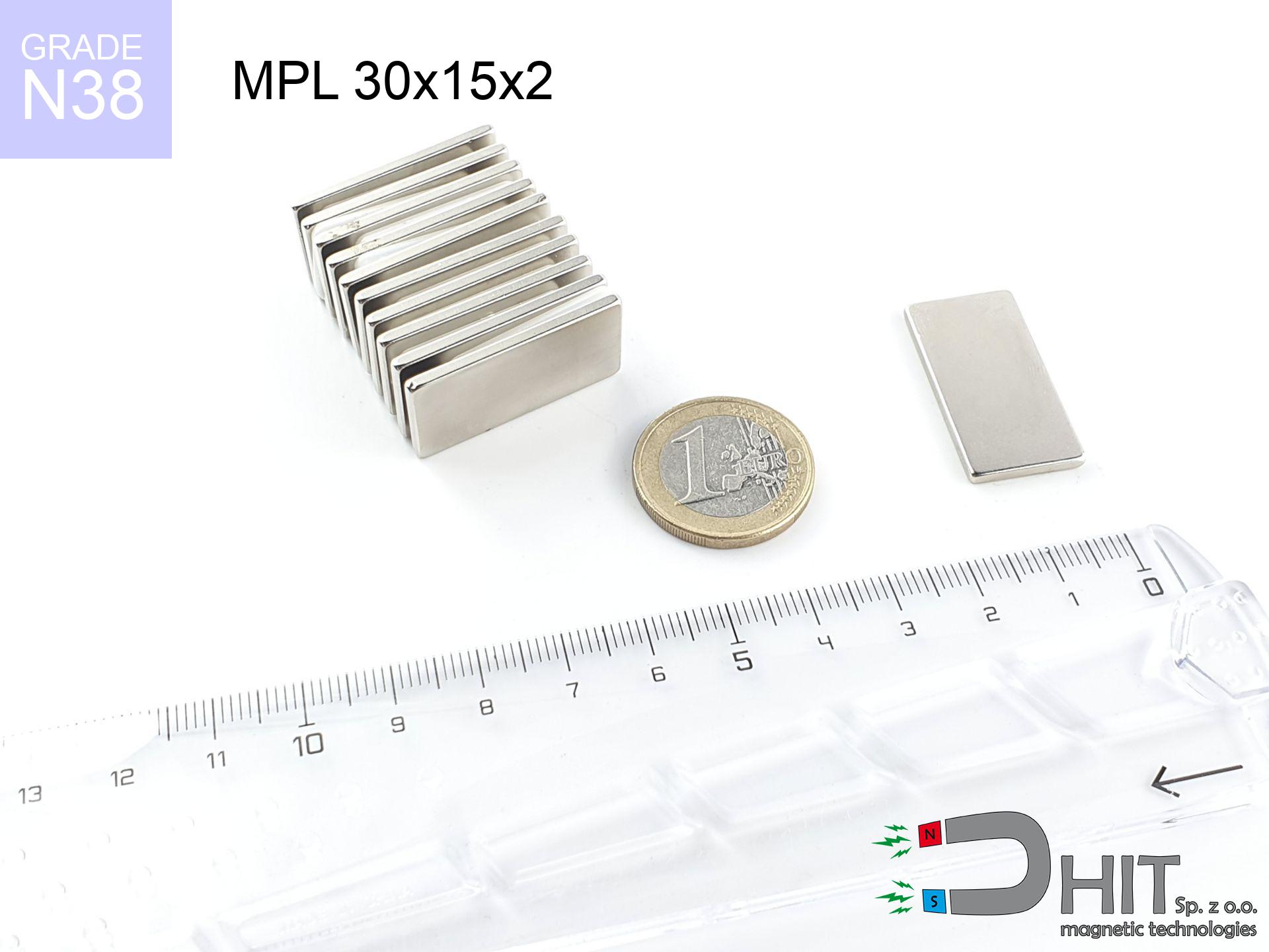
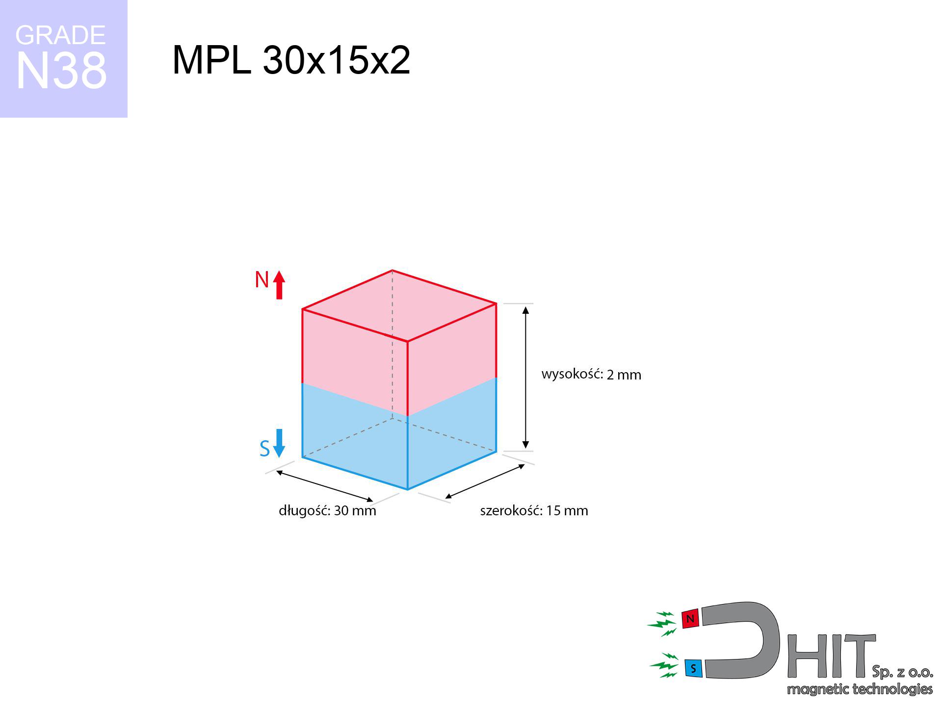
MPL 30x15x2 / N38 - lamellar magnet
lamellar magnet
Catalog no 020140
GTIN/EAN: 5906301811466
length
30 mm [±0,1 mm]
Width
15 mm [±0,1 mm]
Height
2 mm [±0,1 mm]
Weight
6.75 g
Magnetization Direction
↑ axial
Load capacity
2.11 kg / 20.69 N
Magnetic Induction
115.11 mT / 1151 Gs
Coating
[NiCuNi] Nickel
3.89 ZŁ with VAT / pcs + price for transport
3.16 ZŁ net + 23% VAT / pcs
bulk discounts:
Need more?
Call us now
+48 888 99 98 98
otherwise drop us a message by means of
contact form
the contact section.
Specifications along with structure of a neodymium magnet can be tested using our
force calculator.
Order by 14:00 and we’ll ship today!
Technical of the product - MPL 30x15x2 / N38 - lamellar magnet
Specification / characteristics - MPL 30x15x2 / N38 - lamellar magnet
| properties | values |
|---|---|
| Cat. no. | 020140 |
| GTIN/EAN | 5906301811466 |
| Production/Distribution | Dhit sp. z o.o. |
| Country of origin | Poland / China / Germany |
| Customs code | 85059029 |
| length | 30 mm [±0,1 mm] |
| Width | 15 mm [±0,1 mm] |
| Height | 2 mm [±0,1 mm] |
| Weight | 6.75 g |
| Magnetization Direction | ↑ axial |
| Load capacity ~ ? | 2.11 kg / 20.69 N |
| Magnetic Induction ~ ? | 115.11 mT / 1151 Gs |
| Coating | [NiCuNi] Nickel |
| Manufacturing Tolerance | ±0.1 mm |
Magnetic properties of material N38
| properties | values | units |
|---|---|---|
| remenance Br [min. - max.] ? | 12.2-12.6 | kGs |
| remenance Br [min. - max.] ? | 1220-1260 | mT |
| coercivity bHc ? | 10.8-11.5 | kOe |
| coercivity bHc ? | 860-915 | kA/m |
| actual internal force iHc | ≥ 12 | kOe |
| actual internal force iHc | ≥ 955 | kA/m |
| energy density [min. - max.] ? | 36-38 | BH max MGOe |
| energy density [min. - max.] ? | 287-303 | BH max KJ/m |
| max. temperature ? | ≤ 80 | °C |
Physical properties of sintered neodymium magnets Nd2Fe14B at 20°C
| properties | values | units |
|---|---|---|
| Vickers hardness | ≥550 | Hv |
| Density | ≥7.4 | g/cm3 |
| Curie Temperature TC | 312 - 380 | °C |
| Curie Temperature TF | 593 - 716 | °F |
| Specific resistance | 150 | μΩ⋅cm |
| Bending strength | 250 | MPa |
| Compressive strength | 1000~1100 | MPa |
| Thermal expansion parallel (∥) to orientation (M) | (3-4) x 10-6 | °C-1 |
| Thermal expansion perpendicular (⊥) to orientation (M) | -(1-3) x 10-6 | °C-1 |
| Young's modulus | 1.7 x 10⁴ | kg/mm² |
Engineering simulation of the product - technical parameters
The following information represent the outcome of a mathematical simulation. Values are based on models for the class Nd2Fe14B. Real-world performance may differ from theoretical values. Treat these calculations as a reference point during assembly planning.
Table 1: Static pull force (pull vs distance) - interaction chart
MPL 30x15x2 / N38
| Distance (mm) | Induction (Gauss) / mT | Pull Force (kg/lbs/g/N) | Risk Status |
|---|---|---|---|
| 0 mm |
1151 Gs
115.1 mT
|
2.11 kg / 4.65 LBS
2110.0 g / 20.7 N
|
medium risk |
| 1 mm |
1098 Gs
109.8 mT
|
1.92 kg / 4.23 LBS
1920.5 g / 18.8 N
|
weak grip |
| 2 mm |
1019 Gs
101.9 mT
|
1.65 kg / 3.65 LBS
1654.9 g / 16.2 N
|
weak grip |
| 3 mm |
926 Gs
92.6 mT
|
1.37 kg / 3.01 LBS
1365.9 g / 13.4 N
|
weak grip |
| 5 mm |
733 Gs
73.3 mT
|
0.86 kg / 1.89 LBS
855.2 g / 8.4 N
|
weak grip |
| 10 mm |
379 Gs
37.9 mT
|
0.23 kg / 0.50 LBS
228.8 g / 2.2 N
|
weak grip |
| 15 mm |
203 Gs
20.3 mT
|
0.07 kg / 0.14 LBS
65.6 g / 0.6 N
|
weak grip |
| 20 mm |
116 Gs
11.6 mT
|
0.02 kg / 0.05 LBS
21.6 g / 0.2 N
|
weak grip |
| 30 mm |
46 Gs
4.6 mT
|
0.00 kg / 0.01 LBS
3.4 g / 0.0 N
|
weak grip |
| 50 mm |
12 Gs
1.2 mT
|
0.00 kg / 0.00 LBS
0.2 g / 0.0 N
|
weak grip |
Table 2: Shear load (wall)
MPL 30x15x2 / N38
| Distance (mm) | Friction coefficient | Pull Force (kg/lbs/g/N) |
|---|---|---|
| 0 mm | Stal (~0.2) |
0.42 kg / 0.93 LBS
422.0 g / 4.1 N
|
| 1 mm | Stal (~0.2) |
0.38 kg / 0.85 LBS
384.0 g / 3.8 N
|
| 2 mm | Stal (~0.2) |
0.33 kg / 0.73 LBS
330.0 g / 3.2 N
|
| 3 mm | Stal (~0.2) |
0.27 kg / 0.60 LBS
274.0 g / 2.7 N
|
| 5 mm | Stal (~0.2) |
0.17 kg / 0.38 LBS
172.0 g / 1.7 N
|
| 10 mm | Stal (~0.2) |
0.05 kg / 0.10 LBS
46.0 g / 0.5 N
|
| 15 mm | Stal (~0.2) |
0.01 kg / 0.03 LBS
14.0 g / 0.1 N
|
| 20 mm | Stal (~0.2) |
0.00 kg / 0.01 LBS
4.0 g / 0.0 N
|
| 30 mm | Stal (~0.2) |
0.00 kg / 0.00 LBS
0.0 g / 0.0 N
|
| 50 mm | Stal (~0.2) |
0.00 kg / 0.00 LBS
0.0 g / 0.0 N
|
Table 3: Wall mounting (sliding) - vertical pull
MPL 30x15x2 / N38
| Surface type | Friction coefficient / % Mocy | Max load (kg/lbs/g/N) |
|---|---|---|
| Raw steel |
µ = 0.3
30% Nominalnej Siły
|
0.63 kg / 1.40 LBS
633.0 g / 6.2 N
|
| Painted steel (standard) |
µ = 0.2
20% Nominalnej Siły
|
0.42 kg / 0.93 LBS
422.0 g / 4.1 N
|
| Oily/slippery steel |
µ = 0.1
10% Nominalnej Siły
|
0.21 kg / 0.47 LBS
211.0 g / 2.1 N
|
| Magnet with anti-slip rubber |
µ = 0.5
50% Nominalnej Siły
|
1.06 kg / 2.33 LBS
1055.0 g / 10.3 N
|
Table 4: Material efficiency (substrate influence) - power losses
MPL 30x15x2 / N38
| Steel thickness (mm) | % power | Real pull force (kg/lbs/g/N) |
|---|---|---|
| 0.5 mm |
|
0.21 kg / 0.47 LBS
211.0 g / 2.1 N
|
| 1 mm |
|
0.53 kg / 1.16 LBS
527.5 g / 5.2 N
|
| 2 mm |
|
1.06 kg / 2.33 LBS
1055.0 g / 10.3 N
|
| 3 mm |
|
1.58 kg / 3.49 LBS
1582.5 g / 15.5 N
|
| 5 mm |
|
2.11 kg / 4.65 LBS
2110.0 g / 20.7 N
|
| 10 mm |
|
2.11 kg / 4.65 LBS
2110.0 g / 20.7 N
|
| 11 mm |
|
2.11 kg / 4.65 LBS
2110.0 g / 20.7 N
|
| 12 mm |
|
2.11 kg / 4.65 LBS
2110.0 g / 20.7 N
|
Table 5: Thermal resistance (material behavior) - resistance threshold
MPL 30x15x2 / N38
| Ambient temp. (°C) | Power loss | Remaining pull (kg/lbs/g/N) | Status |
|---|---|---|---|
| 20 °C | 0.0% |
2.11 kg / 4.65 LBS
2110.0 g / 20.7 N
|
OK |
| 40 °C | -2.2% |
2.06 kg / 4.55 LBS
2063.6 g / 20.2 N
|
OK |
| 60 °C | -4.4% |
2.02 kg / 4.45 LBS
2017.2 g / 19.8 N
|
|
| 80 °C | -6.6% |
1.97 kg / 4.34 LBS
1970.7 g / 19.3 N
|
|
| 100 °C | -28.8% |
1.50 kg / 3.31 LBS
1502.3 g / 14.7 N
|
Table 6: Two magnets (repulsion) - field range
MPL 30x15x2 / N38
| Gap (mm) | Attraction (kg/lbs) (N-S) | Sliding Force (kg/lbs/g/N) | Repulsion (kg/lbs) (N-N) |
|---|---|---|---|
| 0 mm |
3.67 kg / 8.10 LBS
2 169 Gs
|
0.55 kg / 1.22 LBS
551 g / 5.4 N
|
N/A |
| 1 mm |
3.53 kg / 7.79 LBS
2 257 Gs
|
0.53 kg / 1.17 LBS
530 g / 5.2 N
|
3.18 kg / 7.01 LBS
~0 Gs
|
| 2 mm |
3.34 kg / 7.37 LBS
2 196 Gs
|
0.50 kg / 1.11 LBS
502 g / 4.9 N
|
3.01 kg / 6.64 LBS
~0 Gs
|
| 3 mm |
3.12 kg / 6.89 LBS
2 122 Gs
|
0.47 kg / 1.03 LBS
469 g / 4.6 N
|
2.81 kg / 6.20 LBS
~0 Gs
|
| 5 mm |
2.63 kg / 5.80 LBS
1 948 Gs
|
0.39 kg / 0.87 LBS
395 g / 3.9 N
|
2.37 kg / 5.22 LBS
~0 Gs
|
| 10 mm |
1.49 kg / 3.28 LBS
1 465 Gs
|
0.22 kg / 0.49 LBS
223 g / 2.2 N
|
1.34 kg / 2.96 LBS
~0 Gs
|
| 20 mm |
0.40 kg / 0.88 LBS
758 Gs
|
0.06 kg / 0.13 LBS
60 g / 0.6 N
|
0.36 kg / 0.79 LBS
~0 Gs
|
| 50 mm |
0.01 kg / 0.03 LBS
142 Gs
|
0.00 kg / 0.00 LBS
2 g / 0.0 N
|
0.01 kg / 0.03 LBS
~0 Gs
|
| 60 mm |
0.01 kg / 0.01 LBS
92 Gs
|
0.00 kg / 0.00 LBS
1 g / 0.0 N
|
0.00 kg / 0.00 LBS
~0 Gs
|
| 70 mm |
0.00 kg / 0.01 LBS
63 Gs
|
0.00 kg / 0.00 LBS
0 g / 0.0 N
|
0.00 kg / 0.00 LBS
~0 Gs
|
| 80 mm |
0.00 kg / 0.00 LBS
44 Gs
|
0.00 kg / 0.00 LBS
0 g / 0.0 N
|
0.00 kg / 0.00 LBS
~0 Gs
|
| 90 mm |
0.00 kg / 0.00 LBS
32 Gs
|
0.00 kg / 0.00 LBS
0 g / 0.0 N
|
0.00 kg / 0.00 LBS
~0 Gs
|
| 100 mm |
0.00 kg / 0.00 LBS
24 Gs
|
0.00 kg / 0.00 LBS
0 g / 0.0 N
|
0.00 kg / 0.00 LBS
~0 Gs
|
Table 7: Safety (HSE) (electronics) - precautionary measures
MPL 30x15x2 / N38
| Object / Device | Limit (Gauss) / mT | Safe distance |
|---|---|---|
| Pacemaker | 5 Gs (0.5 mT) | 7.0 cm |
| Hearing aid | 10 Gs (1.0 mT) | 5.5 cm |
| Mechanical watch | 20 Gs (2.0 mT) | 4.5 cm |
| Mobile device | 40 Gs (4.0 mT) | 3.5 cm |
| Remote | 50 Gs (5.0 mT) | 3.0 cm |
| Payment card | 400 Gs (40.0 mT) | 1.0 cm |
| HDD hard drive | 600 Gs (60.0 mT) | 1.0 cm |
Table 8: Impact energy (cracking risk) - warning
MPL 30x15x2 / N38
| Start from (mm) | Speed (km/h) | Energy (J) | Predicted outcome |
|---|---|---|---|
| 10 mm |
19.00 km/h
(5.28 m/s)
|
0.09 J | |
| 30 mm |
30.91 km/h
(8.59 m/s)
|
0.25 J | |
| 50 mm |
39.87 km/h
(11.08 m/s)
|
0.41 J | |
| 100 mm |
56.39 km/h
(15.66 m/s)
|
0.83 J |
Table 9: Coating parameters (durability)
MPL 30x15x2 / N38
| Technical parameter | Value / Description |
|---|---|
| Coating type | [NiCuNi] Nickel |
| Layer structure | Nickel - Copper - Nickel |
| Layer thickness | 10-20 µm |
| Salt spray test (SST) ? | 24 h |
| Recommended environment | Indoors only (dry) |
Table 10: Electrical data (Pc)
MPL 30x15x2 / N38
| Parameter | Value | SI Unit / Description |
|---|---|---|
| Magnetic Flux | 6 236 Mx | 62.4 µWb |
| Pc Coefficient | 0.13 | Low (Flat) |
Table 11: Hydrostatics and buoyancy
MPL 30x15x2 / N38
| Environment | Effective steel pull | Effect |
|---|---|---|
| Air (land) | 2.11 kg | Standard |
| Water (riverbed) |
2.42 kg
(+0.31 kg buoyancy gain)
|
+14.5% |
1. Wall mount (shear)
*Caution: On a vertical surface, the magnet retains merely approx. 20-30% of its nominal pull.
2. Steel thickness impact
*Thin steel (e.g. 0.5mm PC case) drastically weakens the holding force.
3. Power loss vs temp
*For N38 material, the max working temp is 80°C.
4. Demagnetization curve and operating point (B-H)
chart generated for the permeance coefficient Pc (Permeance Coefficient) = 0.13
This simulation demonstrates the magnetic stability of the selected magnet under specific geometric conditions. The solid red line represents the demagnetization curve (material potential), while the dashed blue line is the load line based on the magnet's geometry. The Pc (Permeance Coefficient), also known as the load line slope, is a dimensionless value that describes the relationship between the magnet's shape and its magnetic stability. The intersection of these two lines (the black dot) is the operating point — it determines the actual magnetic flux density generated by the magnet in this specific configuration. A higher Pc value means the magnet is more 'slender' (tall relative to its area), resulting in a higher operating point and better resistance to irreversible demagnetization caused by external fields or temperature. A value of 0.42 is relatively low (typical for flat magnets), meaning the operating point is closer to the 'knee' of the curve — caution is advised when operating at temperatures near the maximum limit to avoid strength loss.
Material specification
| iron (Fe) | 64% – 68% |
| neodymium (Nd) | 29% – 32% |
| boron (B) | 1.1% – 1.2% |
| dysprosium (Dy) | 0.5% – 2.0% |
| coating (Ni-Cu-Ni) | < 0.05% |
Ecology and recycling (GPSR)
| recyclability (EoL) | 100% |
| recycled raw materials | ~10% (pre-cons) |
| carbon footprint | low / zredukowany |
| waste code (EWC) | 16 02 16 |
See also proposals

![BM 380x180x70 [4x M8] - magnetic beam](https://cdn3.dhit.pl/graphics/products/bm-380x180x70-4x-m8-wex.jpg "BM 380x180x70 [4x M8] - magnetic beam")


Advantages and disadvantages of neodymium magnets.
Strengths
- They do not lose strength, even over nearly ten years – the drop in lifting capacity is only ~1% (based on measurements),
- They feature excellent resistance to weakening of magnetic properties as a result of external magnetic sources,
- Thanks to the shimmering finish, the surface of Ni-Cu-Ni, gold-plated, or silver gives an modern appearance,
- Magnets exhibit exceptionally strong magnetic induction on the surface,
- Neodymium magnets are characterized by very high magnetic induction on the magnet surface and can work (depending on the shape) even at a temperature of 230°C or more...
- Thanks to versatility in forming and the ability to customize to client solutions,
- Huge importance in advanced technology sectors – they are commonly used in computer drives, drive modules, precision medical tools, and industrial machines.
- Relatively small size with high pulling force – neodymium magnets offer strong magnetic field in compact dimensions, which makes them useful in small systems
Cons
- At very strong impacts they can crack, therefore we advise placing them in steel cases. A metal housing provides additional protection against damage, as well as increases the magnet's durability.
- We warn that neodymium magnets can reduce their power at high temperatures. To prevent this, we suggest our specialized [AH] magnets, which work effectively even at 230°C.
- Magnets exposed to a humid environment can rust. Therefore when using outdoors, we advise using water-impermeable magnets made of rubber, plastic or other material resistant to moisture
- Due to limitations in realizing nuts and complicated forms in magnets, we recommend using a housing - magnetic holder.
- Possible danger resulting from small fragments of magnets pose a threat, when accidentally swallowed, which is particularly important in the aspect of protecting the youngest. It is also worth noting that small components of these magnets are able to complicate diagnosis medical when they are in the body.
- High unit price – neodymium magnets are more expensive than other types of magnets (e.g. ferrite), which can limit application in large quantities
Pull force analysis
Optimal lifting capacity of a neodymium magnet – what contributes to it?
- with the contact of a sheet made of special test steel, guaranteeing maximum field concentration
- possessing a thickness of min. 10 mm to avoid saturation
- characterized by even structure
- without any insulating layer between the magnet and steel
- under axial application of breakaway force (90-degree angle)
- at room temperature
Lifting capacity in real conditions – factors
- Clearance – the presence of foreign body (paint, tape, air) interrupts the magnetic circuit, which reduces power rapidly (even by 50% at 0.5 mm).
- Angle of force application – maximum parameter is available only during pulling at a 90° angle. The shear force of the magnet along the surface is usually several times lower (approx. 1/5 of the lifting capacity).
- Substrate thickness – for full efficiency, the steel must be sufficiently thick. Thin sheet restricts the lifting capacity (the magnet "punches through" it).
- Material composition – not every steel reacts the same. Alloy additives weaken the interaction with the magnet.
- Plate texture – smooth surfaces ensure maximum contact, which increases field saturation. Rough surfaces reduce efficiency.
- Thermal environment – heating the magnet results in weakening of force. It is worth remembering the thermal limit for a given model.
Holding force was tested on a smooth steel plate of 20 mm thickness, when the force acted perpendicularly, in contrast under shearing force the load capacity is reduced by as much as 75%. Moreover, even a minimal clearance between the magnet’s surface and the plate decreases the load capacity.
Warnings
Machining danger
Combustion risk: Neodymium dust is highly flammable. Do not process magnets in home conditions as this may cause fire.
Demagnetization risk
Keep cool. Neodymium magnets are sensitive to temperature. If you require resistance above 80°C, look for special high-temperature series (H, SH, UH).
Physical harm
Risk of injury: The pulling power is so great that it can result in blood blisters, crushing, and even bone fractures. Use thick gloves.
Phone sensors
An intense magnetic field disrupts the operation of compasses in smartphones and navigation systems. Do not bring magnets close to a smartphone to prevent breaking the sensors.
Allergic reactions
Certain individuals have a hypersensitivity to nickel, which is the typical protective layer for NdFeB magnets. Prolonged contact can result in an allergic reaction. It is best to use protective gloves.
Medical interference
For implant holders: Powerful magnets disrupt medical devices. Maintain at least 30 cm distance or ask another person to handle the magnets.
Powerful field
Handle magnets consciously. Their powerful strength can surprise even professionals. Stay alert and respect their force.
Magnet fragility
NdFeB magnets are sintered ceramics, which means they are prone to chipping. Clashing of two magnets leads to them cracking into shards.
Electronic devices
Data protection: Strong magnets can damage payment cards and delicate electronics (pacemakers, medical aids, mechanical watches).
Danger to the youngest
Strictly keep magnets away from children. Risk of swallowing is significant, and the effects of magnets connecting inside the body are tragic.
Tabela kosztu i czasu dostawy
Płatność przed wysyłką:

GLS kurier
Przesyłka będzie u Ciebie za 2-3 dni
14.99 ZŁ

InPost Paczkomaty 24/7
Przesyłka będzie u Ciebie za 1-2 dni
12.30 ZŁ
Płatność przy odbiorze (pobranie):
GLS kurier
Przesyłka będzie u Ciebie za 1-2 dni
23.00 ZŁ
Rate the product
Your rating