
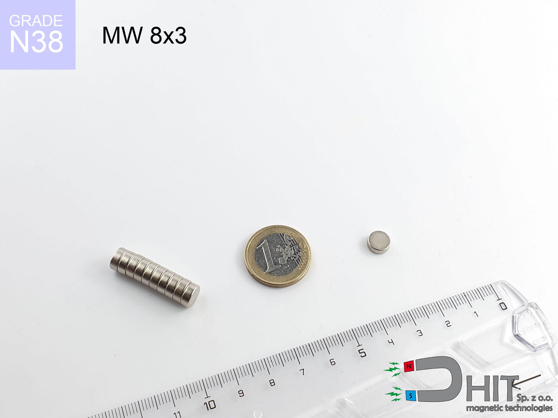
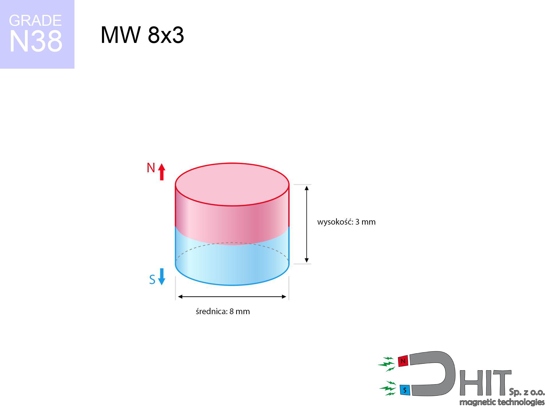
MW 8x3 / N38 - cylindrical magnet
cylindrical magnet
Catalog no 010103
GTIN/EAN: 5906301811022
- Diameter Ø
- 8 mm [±0,1 mm]
- Height
- 3 mm [±0,1 mm]
- Weight
- 1.13 g
- Magnetization Direction
- ↑ axial
- Coating
- [NiCuNi] Nickel
0.701 zł with VAT / pcs + price for transport
0.570 zł net + 23% VAT / pcs
bulk discounts:
Need more?Engineering report for this magnet
Full PDF analysis: pull and shear force, effect of distance, temperature and plate thickness, safety distances and the demagnetization curve.
Call us
+48 22 499 98 98
alternatively get in touch via
inquiry form
the contact section.
Force and structure of a magnet can be tested with our
power calculator.
Orders placed before 14:00 will be shipped the same business day.
Technical - MW 8x3 / N38 - cylindrical magnet
Specification / characteristics - MW 8x3 / N38 - cylindrical magnet
| properties | values |
|---|---|
| Cat. no. | 010103 |
| GTIN/EAN | 5906301811022 |
| Production/Distribution | Dhit sp. z o.o. |
| Country of origin | Poland / China / Germany |
| Customs code | 85059029 |
| Diameter Ø | 8 mm [±0,1 mm] |
| Height | 3 mm [±0,1 mm] |
| Weight | 1.13 g |
| Magnetization Direction | ↑ axial |
| Load capacity ~ ? | 1.70 kg / 16.67 N |
| Magnetic Induction ~ ? | 371.53 mT / 3715 Gs |
| Coating | [NiCuNi] Nickel |
| Manufacturing Tolerance | ±0.1 mm |
Magnetic properties of material N38
| properties | values | units |
|---|---|---|
| remenance Br [min. - max.] ? | 12.2-12.6 | kGs |
| remenance Br [min. - max.] ? | 1220-1260 | mT |
| coercivity bHc ? | 10.8-11.5 | kOe |
| coercivity bHc ? | 860-915 | kA/m |
| actual internal force iHc | ≥ 12 | kOe |
| actual internal force iHc | ≥ 955 | kA/m |
| energy density [min. - max.] ? | 36-38 | BH max MGOe |
| energy density [min. - max.] ? | 287-303 | BH max KJ/m |
| max. temperature ? | ≤ 80 | °C |
Physical properties of sintered neodymium magnets Nd2Fe14B at 20°C
| properties | values | units |
|---|---|---|
| Vickers hardness | ≥550 | Hv |
| Density | ≥7.4 | g/cm3 |
| Curie Temperature TC | 312 - 380 | °C |
| Curie Temperature TF | 593 - 716 | °F |
| Specific resistance | 150 | μΩ⋅cm |
| Bending strength | 250 | MPa |
| Compressive strength | 1000~1100 | MPa |
| Thermal expansion parallel (∥) to orientation (M) | (3-4) x 10-6 | °C-1 |
| Thermal expansion perpendicular (⊥) to orientation (M) | -(1-3) x 10-6 | °C-1 |
| Young's modulus | 1.7 x 10⁴ | kg/mm² |
Technical simulation of the magnet - data
These data represent the direct effect of a physical calculation. Results are based on algorithms for the class Nd2Fe14B. Actual parameters might slightly differ from theoretical values. Treat these calculations as a supplementary guide for designers.
Table 1: Static force (pull vs distance) - characteristics
MW 8x3 / N38
| Distance (mm) | Induction (Gauss) / mT | Pull Force (kg/lbs/g/N) | Risk Status |
|---|---|---|---|
| 0 mm |
3712 Gs
371.2 mT
|
1.70 kg / 3.75 LBS
1700.0 g / 16.7 N
|
low risk |
| 1 mm |
2880 Gs
288.0 mT
|
1.02 kg / 2.26 LBS
1023.3 g / 10.0 N
|
low risk |
| 2 mm |
2069 Gs
206.9 mT
|
0.53 kg / 1.16 LBS
527.9 g / 5.2 N
|
low risk |
| 3 mm |
1439 Gs
143.9 mT
|
0.26 kg / 0.56 LBS
255.3 g / 2.5 N
|
low risk |
| 5 mm |
704 Gs
70.4 mT
|
0.06 kg / 0.13 LBS
61.1 g / 0.6 N
|
low risk |
| 10 mm |
169 Gs
16.9 mT
|
0.00 kg / 0.01 LBS
3.5 g / 0.0 N
|
low risk |
| 15 mm |
62 Gs
6.2 mT
|
0.00 kg / 0.00 LBS
0.5 g / 0.0 N
|
low risk |
| 20 mm |
29 Gs
2.9 mT
|
0.00 kg / 0.00 LBS
0.1 g / 0.0 N
|
low risk |
| 30 mm |
9 Gs
0.9 mT
|
0.00 kg / 0.00 LBS
0.0 g / 0.0 N
|
low risk |
| 50 mm |
2 Gs
0.2 mT
|
0.00 kg / 0.00 LBS
0.0 g / 0.0 N
|
low risk |
Table 2: Slippage capacity (wall)
MW 8x3 / N38
| Distance (mm) | Friction coefficient | Pull Force (kg/lbs/g/N) |
|---|---|---|
| 0 mm | Stal (~0.2) |
0.34 kg / 0.75 LBS
340.0 g / 3.3 N
|
| 1 mm | Stal (~0.2) |
0.20 kg / 0.45 LBS
204.0 g / 2.0 N
|
| 2 mm | Stal (~0.2) |
0.11 kg / 0.23 LBS
106.0 g / 1.0 N
|
| 3 mm | Stal (~0.2) |
0.05 kg / 0.11 LBS
52.0 g / 0.5 N
|
| 5 mm | Stal (~0.2) |
0.01 kg / 0.03 LBS
12.0 g / 0.1 N
|
| 10 mm | Stal (~0.2) |
0.00 kg / 0.00 LBS
0.0 g / 0.0 N
|
| 15 mm | Stal (~0.2) |
0.00 kg / 0.00 LBS
0.0 g / 0.0 N
|
| 20 mm | Stal (~0.2) |
0.00 kg / 0.00 LBS
0.0 g / 0.0 N
|
| 30 mm | Stal (~0.2) |
0.00 kg / 0.00 LBS
0.0 g / 0.0 N
|
| 50 mm | Stal (~0.2) |
0.00 kg / 0.00 LBS
0.0 g / 0.0 N
|
Table 3: Wall mounting (shearing) - vertical pull
MW 8x3 / N38
| Surface type | Friction coefficient / % Mocy | Max load (kg/lbs/g/N) |
|---|---|---|
| Raw steel |
µ = 0.3
30% Nominalnej Siły
|
0.51 kg / 1.12 LBS
510.0 g / 5.0 N
|
| Painted steel (standard) |
µ = 0.2
20% Nominalnej Siły
|
0.34 kg / 0.75 LBS
340.0 g / 3.3 N
|
| Oily/slippery steel |
µ = 0.1
10% Nominalnej Siły
|
0.17 kg / 0.37 LBS
170.0 g / 1.7 N
|
| Magnet with anti-slip rubber |
µ = 0.5
50% Nominalnej Siły
|
0.85 kg / 1.87 LBS
850.0 g / 8.3 N
|
Table 4: Material efficiency (saturation) - sheet metal selection
MW 8x3 / N38
| Steel thickness (mm) | % power | Real pull force (kg/lbs/g/N) |
|---|---|---|
| 0.5 mm |
|
0.17 kg / 0.37 LBS
170.0 g / 1.7 N
|
| 1 mm |
|
0.43 kg / 0.94 LBS
425.0 g / 4.2 N
|
| 2 mm |
|
0.85 kg / 1.87 LBS
850.0 g / 8.3 N
|
| 3 mm |
|
1.28 kg / 2.81 LBS
1275.0 g / 12.5 N
|
| 5 mm |
|
1.70 kg / 3.75 LBS
1700.0 g / 16.7 N
|
| 10 mm |
|
1.70 kg / 3.75 LBS
1700.0 g / 16.7 N
|
| 11 mm |
|
1.70 kg / 3.75 LBS
1700.0 g / 16.7 N
|
| 12 mm |
|
1.70 kg / 3.75 LBS
1700.0 g / 16.7 N
|
Table 5: Working in heat (stability) - thermal limit
MW 8x3 / N38
| Ambient temp. (°C) | Power loss | Remaining pull (kg/lbs/g/N) | Status |
|---|---|---|---|
| 20 °C | 0.0% |
1.70 kg / 3.75 LBS
1700.0 g / 16.7 N
|
OK |
| 40 °C | -2.2% |
1.66 kg / 3.67 LBS
1662.6 g / 16.3 N
|
OK |
| 60 °C | -4.4% |
1.63 kg / 3.58 LBS
1625.2 g / 15.9 N
|
|
| 80 °C | -6.6% |
1.59 kg / 3.50 LBS
1587.8 g / 15.6 N
|
|
| 100 °C | -28.8% |
1.21 kg / 2.67 LBS
1210.4 g / 11.9 N
|
Table 6: Magnet-Magnet interaction (repulsion) - field collision
MW 8x3 / N38
| Gap (mm) | Attraction (kg/lbs) (N-S) | Shear Force (kg/lbs/g/N) | Repulsion (kg/lbs) (N-N) |
|---|---|---|---|
| 0 mm |
4.27 kg / 9.42 LBS
5 146 Gs
|
0.64 kg / 1.41 LBS
641 g / 6.3 N
|
N/A |
| 1 mm |
3.40 kg / 7.50 LBS
6 627 Gs
|
0.51 kg / 1.13 LBS
510 g / 5.0 N
|
3.06 kg / 6.75 LBS
~0 Gs
|
| 2 mm |
2.57 kg / 5.67 LBS
5 761 Gs
|
0.39 kg / 0.85 LBS
386 g / 3.8 N
|
2.31 kg / 5.10 LBS
~0 Gs
|
| 3 mm |
1.87 kg / 4.12 LBS
4 914 Gs
|
0.28 kg / 0.62 LBS
281 g / 2.8 N
|
1.68 kg / 3.71 LBS
~0 Gs
|
| 5 mm |
0.93 kg / 2.04 LBS
3 456 Gs
|
0.14 kg / 0.31 LBS
139 g / 1.4 N
|
0.83 kg / 1.84 LBS
~0 Gs
|
| 10 mm |
0.15 kg / 0.34 LBS
1 408 Gs
|
0.02 kg / 0.05 LBS
23 g / 0.2 N
|
0.14 kg / 0.30 LBS
~0 Gs
|
| 20 mm |
0.01 kg / 0.02 LBS
339 Gs
|
0.00 kg / 0.00 LBS
1 g / 0.0 N
|
0.00 kg / 0.00 LBS
~0 Gs
|
| 50 mm |
0.00 kg / 0.00 LBS
31 Gs
|
0.00 kg / 0.00 LBS
0 g / 0.0 N
|
0.00 kg / 0.00 LBS
~0 Gs
|
| 60 mm |
0.00 kg / 0.00 LBS
19 Gs
|
0.00 kg / 0.00 LBS
0 g / 0.0 N
|
0.00 kg / 0.00 LBS
~0 Gs
|
| 70 mm |
0.00 kg / 0.00 LBS
12 Gs
|
0.00 kg / 0.00 LBS
0 g / 0.0 N
|
0.00 kg / 0.00 LBS
~0 Gs
|
| 80 mm |
0.00 kg / 0.00 LBS
8 Gs
|
0.00 kg / 0.00 LBS
0 g / 0.0 N
|
0.00 kg / 0.00 LBS
~0 Gs
|
| 90 mm |
0.00 kg / 0.00 LBS
6 Gs
|
0.00 kg / 0.00 LBS
0 g / 0.0 N
|
0.00 kg / 0.00 LBS
~0 Gs
|
| 100 mm |
0.00 kg / 0.00 LBS
4 Gs
|
0.00 kg / 0.00 LBS
0 g / 0.0 N
|
0.00 kg / 0.00 LBS
~0 Gs
|
Table 7: Protective zones (implants) - warnings
MW 8x3 / N38
| Object / Device | Limit (Gauss) / mT | Safe distance |
|---|---|---|
| Pacemaker | 5 Gs (0.5 mT) | 4.0 cm |
| Hearing aid | 10 Gs (1.0 mT) | 3.0 cm |
| Mechanical watch | 20 Gs (2.0 mT) | 2.5 cm |
| Phone / Smartphone | 40 Gs (4.0 mT) | 2.0 cm |
| Car key | 50 Gs (5.0 mT) | 2.0 cm |
| Payment card | 400 Gs (40.0 mT) | 1.0 cm |
| HDD hard drive | 600 Gs (60.0 mT) | 1.0 cm |
Table 8: Collisions (cracking risk) - collision effects
MW 8x3 / N38
| Start from (mm) | Speed (km/h) | Energy (J) | Predicted outcome |
|---|---|---|---|
| 10 mm |
25.33 km/h
(7.04 m/s)
|
0.03 J | |
| 30 mm |
25.37 km/h
(7.05 m/s)
|
0.03 J | |
| 50 mm |
25.37 km/h
(7.05 m/s)
|
0.03 J | |
| 100 mm |
25.37 km/h
(7.05 m/s)
|
0.03 J |
Table 9: Corrosion resistance
MW 8x3 / N38
| Technical parameter | Value / Description |
|---|---|
| Coating type | [NiCuNi] Nickel |
| Layer structure | Nickel - Copper - Nickel |
| Layer thickness | 10-20 µm |
| Salt spray test (SST) ? | 24 h |
| Recommended environment | Indoors only (dry) |
Table 10: Electrical data (Pc)
MW 8x3 / N38
| Parameter | Value | SI Unit / Description |
|---|---|---|
| Magnetic Flux | 1 946 Mx | 19.5 µWb |
| Pc Coefficient | 0.48 | Low (Flat) |
Table 11: Submerged application
MW 8x3 / N38
| Environment | Effective steel pull | Effect |
|---|---|---|
| Air (land) | 1.70 kg | Standard |
| Water (riverbed) |
1.95 kg
(+0.25 kg buoyancy gain)
|
+14.5% |
1. Shear force
*Caution: On a vertical wall, the magnet retains merely a fraction of its max power.
2. Efficiency vs thickness
*Thin metal sheet (e.g. computer case) significantly weakens the holding force.
3. Heat tolerance
*For N38 material, the max working temp is 80°C.
4. Demagnetization curve and operating point (B-H)
chart generated for the permeance coefficient Pc (Permeance Coefficient) = 0.48
The chart above illustrates the magnetic characteristics of the material within the second quadrant of the hysteresis loop. The solid red line represents the demagnetization curve (material potential), while the dashed blue line is the load line based on the magnet's geometry. The Pc (Permeance Coefficient), also known as the load line slope, is a dimensionless value that describes the relationship between the magnet's shape and its magnetic stability. The intersection of these two lines (the black dot) is the operating point — it determines the actual magnetic flux density generated by the magnet in this specific configuration. A higher Pc value means the magnet is more 'slender' (tall relative to its area), resulting in a higher operating point and better resistance to irreversible demagnetization caused by external fields or temperature. A value of 0.42 is relatively low (typical for flat magnets), meaning the operating point is closer to the 'knee' of the curve — caution is advised when operating at temperatures near the maximum limit to avoid strength loss.
Elemental analysis
| iron (Fe) | 64% – 68% |
| neodymium (Nd) | 29% – 32% |
| boron (B) | 1.1% – 1.2% |
| dysprosium (Dy) | 0.5% – 2.0% |
| coating (Ni-Cu-Ni) | < 0.05% |
Environmental data
| recyclability (EoL) | 100% |
| recycled raw materials | ~10% (pre-cons) |
| carbon footprint | low / zredukowany |
| waste code (EWC) | 16 02 16 |
Other products
![UMGGW 66x8.5 [M8] GW / N38 - magnetic holder rubber internal thread](https://cdn3.dhit.pl/graphics/products/umg-66x8.5-m6-gw-wud.jpg "UMGGW 66x8.5 [M8] GW / N38 - magnetic holder rubber internal thread")


Strengths and weaknesses of neodymium magnets.
Pros
- They virtually do not lose power, because even after 10 years the performance loss is only ~1% (according to literature),
- They possess excellent resistance to weakening of magnetic properties due to external magnetic sources,
- The use of an elegant coating of noble metals (nickel, gold, silver) causes the element to have aesthetics,
- Magnetic induction on the surface of the magnet remains strong,
- Made from properly selected components, these magnets show impressive resistance to high heat, enabling them to function (depending on their form) at temperatures up to 230°C and above...
- Possibility of accurate modeling as well as optimizing to individual applications,
- Key role in innovative solutions – they are commonly used in magnetic memories, drive modules, medical equipment, as well as other advanced devices.
- Relatively small size with high pulling force – neodymium magnets offer strong magnetic field in small dimensions, which enables their usage in compact constructions
Limitations
- They are fragile upon heavy impacts. To avoid cracks, it is worth protecting magnets in a protective case. Such protection not only protects the magnet but also increases its resistance to damage
- Neodymium magnets lose their force under the influence of heating. As soon as 80°C is exceeded, many of them start losing their force. Therefore, we recommend our special magnets marked [AH], which maintain durability even at temperatures up to 230°C
- Due to the susceptibility of magnets to corrosion in a humid environment, we suggest using waterproof magnets made of rubber, plastic or other material stable to moisture, when using outdoors
- Due to limitations in producing nuts and complex shapes in magnets, we propose using casing - magnetic mechanism.
- Potential hazard related to microscopic parts of magnets can be dangerous, when accidentally swallowed, which gains importance in the context of child safety. Furthermore, small elements of these products can disrupt the diagnostic process medical after entering the body.
- High unit price – neodymium magnets have a higher price than other types of magnets (e.g. ferrite), which hinders application in large quantities
Pull force analysis
Maximum lifting force for a neodymium magnet – what contributes to it?
- with the use of a sheet made of low-carbon steel, ensuring maximum field concentration
- with a cross-section no less than 10 mm
- characterized by smoothness
- without any air gap between the magnet and steel
- during pulling in a direction vertical to the mounting surface
- in neutral thermal conditions
Practical aspects of lifting capacity – factors
- Distance – existence of foreign body (paint, tape, gap) acts as an insulator, which lowers capacity steeply (even by 50% at 0.5 mm).
- Force direction – remember that the magnet holds strongest perpendicularly. Under sliding down, the capacity drops significantly, often to levels of 20-30% of the maximum value.
- Wall thickness – thin material does not allow full use of the magnet. Magnetic flux passes through the material instead of converting into lifting capacity.
- Material composition – not every steel reacts the same. Alloy additives weaken the interaction with the magnet.
- Surface finish – ideal contact is obtained only on smooth steel. Any scratches and bumps create air cushions, weakening the magnet.
- Thermal factor – high temperature weakens pulling force. Too high temperature can permanently damage the magnet.
Lifting capacity testing was conducted on plates with a smooth surface of suitable thickness, under perpendicular forces, in contrast under shearing force the lifting capacity is smaller. Additionally, even a small distance between the magnet and the plate decreases the lifting capacity.
Warnings
GPS Danger
Be aware: rare earth magnets produce a field that interferes with sensitive sensors. Keep a safe distance from your mobile, tablet, and GPS.
Allergy Warning
Nickel alert: The Ni-Cu-Ni coating consists of nickel. If redness happens, cease handling magnets and use protective gear.
Medical interference
For implant holders: Powerful magnets disrupt electronics. Keep at least 30 cm distance or ask another person to work with the magnets.
Dust explosion hazard
Drilling and cutting of NdFeB material poses a fire risk. Magnetic powder oxidizes rapidly with oxygen and is hard to extinguish.
Conscious usage
Before starting, check safety instructions. Uncontrolled attraction can destroy the magnet or injure your hand. Think ahead.
Data carriers
Equipment safety: Neodymium magnets can ruin data carriers and sensitive devices (pacemakers, medical aids, mechanical watches).
Operating temperature
Watch the temperature. Heating the magnet above 80 degrees Celsius will destroy its properties and pulling force.
Keep away from children
Strictly store magnets out of reach of children. Choking hazard is significant, and the consequences of magnets clamping inside the body are very dangerous.
Serious injuries
Large magnets can crush fingers instantly. Never put your hand between two strong magnets.
Risk of cracking
Despite metallic appearance, the material is brittle and cannot withstand shocks. Do not hit, as the magnet may shatter into sharp, dangerous pieces.
Tabela kosztu i czasu dostawy
Płatność przed wysyłką:

GLS kurier
Przesyłka będzie u Ciebie za 2-3 dni
14.99 ZŁ

InPost Paczkomaty 24/7
Przesyłka będzie u Ciebie za 1-2 dni
12.30 ZŁ
Płatność przy odbiorze (pobranie):
GLS kurier
Przesyłka będzie u Ciebie za 1-2 dni
23.00 ZŁ
Rate the product
Your rating