

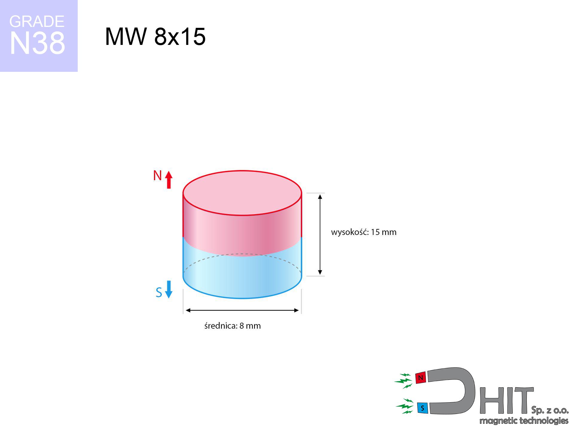
MW 8x15 / N38 - cylindrical magnet
cylindrical magnet
Catalog no 010102
GTIN/EAN: 5906301811015
Diameter Ø
8 mm [±0,1 mm]
Height
15 mm [±0,1 mm]
Weight
5.65 g
Magnetization Direction
↑ axial
Load capacity
1.47 kg / 14.45 N
Magnetic Induction
598.12 mT / 5981 Gs
Coating
[NiCuNi] Nickel
3.44 ZŁ with VAT / pcs + price for transport
2.80 ZŁ net + 23% VAT / pcs
bulk discounts:
Need more?Engineering report for this magnet
Full PDF analysis: pull and shear force, effect of distance, temperature and plate thickness, safety distances and the demagnetization curve.
Pick up the phone and ask
+48 22 499 98 98
alternatively let us know by means of
request form
the contact form page.
Force along with structure of magnets can be reviewed on our
force calculator.
Orders placed before 14:00 will be shipped the same business day.
Technical specification - MW 8x15 / N38 - cylindrical magnet
Specification / characteristics - MW 8x15 / N38 - cylindrical magnet
| properties | values |
|---|---|
| Cat. no. | 010102 |
| GTIN/EAN | 5906301811015 |
| Production/Distribution | Dhit sp. z o.o. |
| Country of origin | Poland / China / Germany |
| Customs code | 85059029 |
| Diameter Ø | 8 mm [±0,1 mm] |
| Height | 15 mm [±0,1 mm] |
| Weight | 5.65 g |
| Magnetization Direction | ↑ axial |
| Load capacity ~ ? | 1.47 kg / 14.45 N |
| Magnetic Induction ~ ? | 598.12 mT / 5981 Gs |
| Coating | [NiCuNi] Nickel |
| Manufacturing Tolerance | ±0.1 mm |
Magnetic properties of material N38
| properties | values | units |
|---|---|---|
| remenance Br [min. - max.] ? | 12.2-12.6 | kGs |
| remenance Br [min. - max.] ? | 1220-1260 | mT |
| coercivity bHc ? | 10.8-11.5 | kOe |
| coercivity bHc ? | 860-915 | kA/m |
| actual internal force iHc | ≥ 12 | kOe |
| actual internal force iHc | ≥ 955 | kA/m |
| energy density [min. - max.] ? | 36-38 | BH max MGOe |
| energy density [min. - max.] ? | 287-303 | BH max KJ/m |
| max. temperature ? | ≤ 80 | °C |
Physical properties of sintered neodymium magnets Nd2Fe14B at 20°C
| properties | values | units |
|---|---|---|
| Vickers hardness | ≥550 | Hv |
| Density | ≥7.4 | g/cm3 |
| Curie Temperature TC | 312 - 380 | °C |
| Curie Temperature TF | 593 - 716 | °F |
| Specific resistance | 150 | μΩ⋅cm |
| Bending strength | 250 | MPa |
| Compressive strength | 1000~1100 | MPa |
| Thermal expansion parallel (∥) to orientation (M) | (3-4) x 10-6 | °C-1 |
| Thermal expansion perpendicular (⊥) to orientation (M) | -(1-3) x 10-6 | °C-1 |
| Young's modulus | 1.7 x 10⁴ | kg/mm² |
Technical analysis of the assembly - report
Presented data are the direct effect of a physical calculation. Results rely on algorithms for the class Nd2Fe14B. Operational conditions may deviate from the simulation results. Please consider these data as a supplementary guide during assembly planning.
Table 1: Static pull force (pull vs distance) - interaction chart
MW 8x15 / N38
| Distance (mm) | Induction (Gauss) / mT | Pull Force (kg/lbs/g/N) | Risk Status |
|---|---|---|---|
| 0 mm |
5975 Gs
597.5 mT
|
1.47 kg / 3.24 pounds
1470.0 g / 14.4 N
|
safe |
| 1 mm |
4511 Gs
451.1 mT
|
0.84 kg / 1.85 pounds
837.8 g / 8.2 N
|
safe |
| 2 mm |
3262 Gs
326.2 mT
|
0.44 kg / 0.97 pounds
438.2 g / 4.3 N
|
safe |
| 3 mm |
2332 Gs
233.2 mT
|
0.22 kg / 0.49 pounds
224.0 g / 2.2 N
|
safe |
| 5 mm |
1238 Gs
123.8 mT
|
0.06 kg / 0.14 pounds
63.1 g / 0.6 N
|
safe |
| 10 mm |
366 Gs
36.6 mT
|
0.01 kg / 0.01 pounds
5.5 g / 0.1 N
|
safe |
| 15 mm |
155 Gs
15.5 mT
|
0.00 kg / 0.00 pounds
1.0 g / 0.0 N
|
safe |
| 20 mm |
80 Gs
8.0 mT
|
0.00 kg / 0.00 pounds
0.3 g / 0.0 N
|
safe |
| 30 mm |
30 Gs
3.0 mT
|
0.00 kg / 0.00 pounds
0.0 g / 0.0 N
|
safe |
| 50 mm |
8 Gs
0.8 mT
|
0.00 kg / 0.00 pounds
0.0 g / 0.0 N
|
safe |
Table 2: Slippage force (vertical surface)
MW 8x15 / N38
| Distance (mm) | Friction coefficient | Pull Force (kg/lbs/g/N) |
|---|---|---|
| 0 mm | Stal (~0.2) |
0.29 kg / 0.65 pounds
294.0 g / 2.9 N
|
| 1 mm | Stal (~0.2) |
0.17 kg / 0.37 pounds
168.0 g / 1.6 N
|
| 2 mm | Stal (~0.2) |
0.09 kg / 0.19 pounds
88.0 g / 0.9 N
|
| 3 mm | Stal (~0.2) |
0.04 kg / 0.10 pounds
44.0 g / 0.4 N
|
| 5 mm | Stal (~0.2) |
0.01 kg / 0.03 pounds
12.0 g / 0.1 N
|
| 10 mm | Stal (~0.2) |
0.00 kg / 0.00 pounds
2.0 g / 0.0 N
|
| 15 mm | Stal (~0.2) |
0.00 kg / 0.00 pounds
0.0 g / 0.0 N
|
| 20 mm | Stal (~0.2) |
0.00 kg / 0.00 pounds
0.0 g / 0.0 N
|
| 30 mm | Stal (~0.2) |
0.00 kg / 0.00 pounds
0.0 g / 0.0 N
|
| 50 mm | Stal (~0.2) |
0.00 kg / 0.00 pounds
0.0 g / 0.0 N
|
Table 3: Wall mounting (shearing) - vertical pull
MW 8x15 / N38
| Surface type | Friction coefficient / % Mocy | Max load (kg/lbs/g/N) |
|---|---|---|
| Raw steel |
µ = 0.3
30% Nominalnej Siły
|
0.44 kg / 0.97 pounds
441.0 g / 4.3 N
|
| Painted steel (standard) |
µ = 0.2
20% Nominalnej Siły
|
0.29 kg / 0.65 pounds
294.0 g / 2.9 N
|
| Oily/slippery steel |
µ = 0.1
10% Nominalnej Siły
|
0.15 kg / 0.32 pounds
147.0 g / 1.4 N
|
| Magnet with anti-slip rubber |
µ = 0.5
50% Nominalnej Siły
|
0.74 kg / 1.62 pounds
735.0 g / 7.2 N
|
Table 4: Steel thickness (substrate influence) - power losses
MW 8x15 / N38
| Steel thickness (mm) | % power | Real pull force (kg/lbs/g/N) |
|---|---|---|
| 0.5 mm |
|
0.15 kg / 0.32 pounds
147.0 g / 1.4 N
|
| 1 mm |
|
0.37 kg / 0.81 pounds
367.5 g / 3.6 N
|
| 2 mm |
|
0.74 kg / 1.62 pounds
735.0 g / 7.2 N
|
| 3 mm |
|
1.10 kg / 2.43 pounds
1102.5 g / 10.8 N
|
| 5 mm |
|
1.47 kg / 3.24 pounds
1470.0 g / 14.4 N
|
| 10 mm |
|
1.47 kg / 3.24 pounds
1470.0 g / 14.4 N
|
| 11 mm |
|
1.47 kg / 3.24 pounds
1470.0 g / 14.4 N
|
| 12 mm |
|
1.47 kg / 3.24 pounds
1470.0 g / 14.4 N
|
Table 5: Thermal resistance (material behavior) - power drop
MW 8x15 / N38
| Ambient temp. (°C) | Power loss | Remaining pull (kg/lbs/g/N) | Status |
|---|---|---|---|
| 20 °C | 0.0% |
1.47 kg / 3.24 pounds
1470.0 g / 14.4 N
|
OK |
| 40 °C | -2.2% |
1.44 kg / 3.17 pounds
1437.7 g / 14.1 N
|
OK |
| 60 °C | -4.4% |
1.41 kg / 3.10 pounds
1405.3 g / 13.8 N
|
OK |
| 80 °C | -6.6% |
1.37 kg / 3.03 pounds
1373.0 g / 13.5 N
|
|
| 100 °C | -28.8% |
1.05 kg / 2.31 pounds
1046.6 g / 10.3 N
|
Table 6: Two magnets (repulsion) - field collision
MW 8x15 / N38
| Gap (mm) | Attraction (kg/lbs) (N-S) | Shear Strength (kg/lbs/g/N) | Repulsion (kg/lbs) (N-N) |
|---|---|---|---|
| 0 mm |
11.06 kg / 24.39 pounds
6 130 Gs
|
1.66 kg / 3.66 pounds
1660 g / 16.3 N
|
N/A |
| 1 mm |
8.49 kg / 18.72 pounds
10 469 Gs
|
1.27 kg / 2.81 pounds
1274 g / 12.5 N
|
7.64 kg / 16.85 pounds
~0 Gs
|
| 2 mm |
6.31 kg / 13.90 pounds
9 022 Gs
|
0.95 kg / 2.09 pounds
946 g / 9.3 N
|
5.68 kg / 12.51 pounds
~0 Gs
|
| 3 mm |
4.59 kg / 10.12 pounds
7 697 Gs
|
0.69 kg / 1.52 pounds
688 g / 6.8 N
|
4.13 kg / 9.11 pounds
~0 Gs
|
| 5 mm |
2.36 kg / 5.20 pounds
5 516 Gs
|
0.35 kg / 0.78 pounds
354 g / 3.5 N
|
2.12 kg / 4.68 pounds
~0 Gs
|
| 10 mm |
0.48 kg / 1.05 pounds
2 476 Gs
|
0.07 kg / 0.16 pounds
71 g / 0.7 N
|
0.43 kg / 0.94 pounds
~0 Gs
|
| 20 mm |
0.04 kg / 0.09 pounds
731 Gs
|
0.01 kg / 0.01 pounds
6 g / 0.1 N
|
0.04 kg / 0.08 pounds
~0 Gs
|
| 50 mm |
0.00 kg / 0.00 pounds
94 Gs
|
0.00 kg / 0.00 pounds
0 g / 0.0 N
|
0.00 kg / 0.00 pounds
~0 Gs
|
| 60 mm |
0.00 kg / 0.00 pounds
60 Gs
|
0.00 kg / 0.00 pounds
0 g / 0.0 N
|
0.00 kg / 0.00 pounds
~0 Gs
|
| 70 mm |
0.00 kg / 0.00 pounds
41 Gs
|
0.00 kg / 0.00 pounds
0 g / 0.0 N
|
0.00 kg / 0.00 pounds
~0 Gs
|
| 80 mm |
0.00 kg / 0.00 pounds
29 Gs
|
0.00 kg / 0.00 pounds
0 g / 0.0 N
|
0.00 kg / 0.00 pounds
~0 Gs
|
| 90 mm |
0.00 kg / 0.00 pounds
21 Gs
|
0.00 kg / 0.00 pounds
0 g / 0.0 N
|
0.00 kg / 0.00 pounds
~0 Gs
|
| 100 mm |
0.00 kg / 0.00 pounds
16 Gs
|
0.00 kg / 0.00 pounds
0 g / 0.0 N
|
0.00 kg / 0.00 pounds
~0 Gs
|
Table 7: Safety (HSE) (electronics) - warnings
MW 8x15 / N38
| Object / Device | Limit (Gauss) / mT | Safe distance |
|---|---|---|
| Pacemaker | 5 Gs (0.5 mT) | 6.0 cm |
| Hearing aid | 10 Gs (1.0 mT) | 5.0 cm |
| Timepiece | 20 Gs (2.0 mT) | 4.0 cm |
| Phone / Smartphone | 40 Gs (4.0 mT) | 3.0 cm |
| Remote | 50 Gs (5.0 mT) | 2.5 cm |
| Payment card | 400 Gs (40.0 mT) | 1.0 cm |
| HDD hard drive | 600 Gs (60.0 mT) | 1.0 cm |
Table 8: Dynamics (kinetic energy) - warning
MW 8x15 / N38
| Start from (mm) | Speed (km/h) | Energy (J) | Predicted outcome |
|---|---|---|---|
| 10 mm |
16.31 km/h
(4.53 m/s)
|
0.06 J | |
| 30 mm |
28.18 km/h
(7.83 m/s)
|
0.17 J | |
| 50 mm |
36.37 km/h
(10.10 m/s)
|
0.29 J | |
| 100 mm |
51.44 km/h
(14.29 m/s)
|
0.58 J |
Table 9: Surface protection spec
MW 8x15 / N38
| Technical parameter | Value / Description |
|---|---|
| Coating type | [NiCuNi] Nickel |
| Layer structure | Nickel - Copper - Nickel |
| Layer thickness | 10-20 µm |
| Salt spray test (SST) ? | 24 h |
| Recommended environment | Indoors only (dry) |
Table 10: Electrical data (Pc)
MW 8x15 / N38
| Parameter | Value | SI Unit / Description |
|---|---|---|
| Magnetic Flux | 3 306 Mx | 33.1 µWb |
| Pc Coefficient | 1.19 | High (Stable) |
Table 11: Hydrostatics and buoyancy
MW 8x15 / N38
| Environment | Effective steel pull | Effect |
|---|---|---|
| Air (land) | 1.47 kg | Standard |
| Water (riverbed) |
1.68 kg
(+0.21 kg buoyancy gain)
|
+14.5% |
1. Vertical hold
*Note: On a vertical surface, the magnet holds just a fraction of its nominal pull.
2. Steel saturation
*Thin metal sheet (e.g. computer case) severely limits the holding force.
3. Power loss vs temp
*For standard magnets, the max working temp is 80°C.
4. Demagnetization curve and operating point (B-H)
chart generated for the permeance coefficient Pc (Permeance Coefficient) = 1.19
The chart above illustrates the magnetic characteristics of the material within the second quadrant of the hysteresis loop. The solid red line represents the demagnetization curve (material potential), while the dashed blue line is the load line based on the magnet's geometry. The Pc (Permeance Coefficient), also known as the load line slope, is a dimensionless value that describes the relationship between the magnet's shape and its magnetic stability. The intersection of these two lines (the black dot) is the operating point — it determines the actual magnetic flux density generated by the magnet in this specific configuration. A higher Pc value means the magnet is more 'slender' (tall relative to its area), resulting in a higher operating point and better resistance to irreversible demagnetization caused by external fields or temperature. A value of 0.42 is relatively low (typical for flat magnets), meaning the operating point is closer to the 'knee' of the curve — caution is advised when operating at temperatures near the maximum limit to avoid strength loss.
Chemical composition
| iron (Fe) | 64% – 68% |
| neodymium (Nd) | 29% – 32% |
| boron (B) | 1.1% – 1.2% |
| dysprosium (Dy) | 0.5% – 2.0% |
| coating (Ni-Cu-Ni) | < 0.05% |
Sustainability
| recyclability (EoL) | 100% |
| recycled raw materials | ~10% (pre-cons) |
| carbon footprint | low / zredukowany |
| waste code (EWC) | 16 02 16 |
Check out more proposals
![SM 25x350 [2xM8] / N52 - magnetic separator](https://cdn3.dhit.pl/graphics/products/sm-25x350-2xm8-geb.jpg "SM 25x350 [2xM8] / N52 - magnetic separator")


![UMH 25x8x45 [M5] / N38 - magnetic holder with hook](https://cdn3.dhit.pl/graphics/products/umh-25x8x45-m5-cep.jpg "UMH 25x8x45 [M5] / N38 - magnetic holder with hook")
Advantages as well as disadvantages of neodymium magnets.
Strengths
- They do not lose strength, even after nearly 10 years – the decrease in lifting capacity is only ~1% (based on measurements),
- They maintain their magnetic properties even under external field action,
- In other words, due to the smooth finish of nickel, the element looks attractive,
- Magnetic induction on the working part of the magnet turns out to be very high,
- Due to their durability and thermal resistance, neodymium magnets can operate (depending on the form) even at high temperatures reaching 230°C or more...
- Possibility of exact shaping and adjusting to individual needs,
- Universal use in modern industrial fields – they serve a role in magnetic memories, brushless drives, advanced medical instruments, as well as complex engineering applications.
- Compactness – despite small sizes they generate large force, making them ideal for precision applications
Limitations
- They are prone to damage upon heavy impacts. To avoid cracks, it is worth protecting magnets using a steel holder. Such protection not only shields the magnet but also increases its resistance to damage
- Neodymium magnets lose their force under the influence of heating. As soon as 80°C is exceeded, many of them start losing their power. Therefore, we recommend our special magnets marked [AH], which maintain durability even at temperatures up to 230°C
- Due to the susceptibility of magnets to corrosion in a humid environment, we suggest using waterproof magnets made of rubber, plastic or other material immune to moisture, when using outdoors
- Limited possibility of producing nuts in the magnet and complex shapes - preferred is casing - magnetic holder.
- Health risk related to microscopic parts of magnets are risky, in case of ingestion, which becomes key in the context of child health protection. Furthermore, small components of these devices are able to be problematic in diagnostics medical in case of swallowing.
- Due to expensive raw materials, their price is relatively high,
Lifting parameters
Magnetic strength at its maximum – what it depends on?
- on a base made of structural steel, perfectly concentrating the magnetic flux
- whose transverse dimension equals approx. 10 mm
- with an polished contact surface
- with zero gap (no impurities)
- for force applied at a right angle (in the magnet axis)
- in stable room temperature
Magnet lifting force in use – key factors
- Clearance – the presence of any layer (rust, dirt, air) interrupts the magnetic circuit, which lowers power steeply (even by 50% at 0.5 mm).
- Direction of force – highest force is obtained only during perpendicular pulling. The shear force of the magnet along the surface is standardly several times lower (approx. 1/5 of the lifting capacity).
- Element thickness – to utilize 100% power, the steel must be adequately massive. Thin sheet restricts the attraction force (the magnet "punches through" it).
- Steel grade – ideal substrate is pure iron steel. Hardened steels may have worse magnetic properties.
- Surface finish – full contact is possible only on polished steel. Rough texture create air cushions, reducing force.
- Thermal conditions – NdFeB sinters have a sensitivity to temperature. At higher temperatures they are weaker, and at low temperatures gain strength (up to a certain limit).
Lifting capacity testing was conducted on plates with a smooth surface of suitable thickness, under a perpendicular pulling force, whereas under parallel forces the load capacity is reduced by as much as 75%. Moreover, even a minimal clearance between the magnet and the plate lowers the lifting capacity.
Safe handling of neodymium magnets
Magnets are brittle
Despite metallic appearance, neodymium is delicate and not impact-resistant. Avoid impacts, as the magnet may shatter into hazardous fragments.
Choking Hazard
Product intended for adults. Small elements pose a choking risk, causing intestinal necrosis. Store out of reach of children and animals.
Safe distance
Do not bring magnets close to a purse, computer, or screen. The magnetism can irreversibly ruin these devices and wipe information from cards.
Sensitization to coating
Studies show that nickel (the usual finish) is a potent allergen. For allergy sufferers, avoid direct skin contact or choose coated magnets.
Dust explosion hazard
Fire warning: Neodymium dust is explosive. Avoid machining magnets without safety gear as this may cause fire.
Implant safety
Health Alert: Neodymium magnets can turn off heart devices and defibrillators. Do not approach if you have electronic implants.
Pinching danger
Protect your hands. Two large magnets will join immediately with a force of several hundred kilograms, crushing anything in their path. Be careful!
Compass and GPS
Be aware: neodymium magnets generate a field that interferes with precision electronics. Keep a safe distance from your mobile, device, and navigation systems.
Thermal limits
Monitor thermal conditions. Exposing the magnet above 80 degrees Celsius will ruin its properties and pulling force.
Safe operation
Handle with care. Rare earth magnets act from a distance and connect with huge force, often faster than you can react.
Tabela kosztu i czasu dostawy
Płatność przed wysyłką:

GLS kurier
Przesyłka będzie u Ciebie za 2-3 dni
14.99 ZŁ

InPost Paczkomaty 24/7
Przesyłka będzie u Ciebie za 1-2 dni
12.30 ZŁ
Płatność przy odbiorze (pobranie):
GLS kurier
Przesyłka będzie u Ciebie za 1-2 dni
23.00 ZŁ
Rate the product
Your rating