

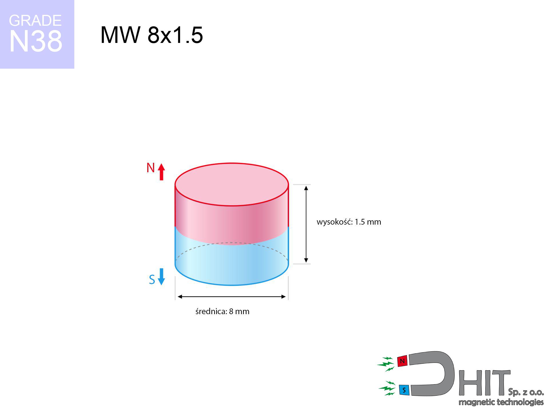
MW 8x1.5 / N38 - cylindrical magnet
cylindrical magnet
Catalog no 010101
GTIN/EAN: 5906301811008
Diameter Ø
8 mm [±0,1 mm]
Height
1.5 mm [±0,1 mm]
Weight
0.57 g
Magnetization Direction
↑ axial
Load capacity
0.74 kg / 7.27 N
Magnetic Induction
217.52 mT / 2175 Gs
Coating
[NiCuNi] Nickel
0.455 ZŁ with VAT / pcs + price for transport
0.370 ZŁ net + 23% VAT / pcs
bulk discounts:
Need more?Engineering report for this magnet
Full PDF analysis: pull and shear force, effect of distance, temperature and plate thickness, safety distances and the demagnetization curve.
Call us now
+48 22 499 98 98
otherwise drop us a message using
contact form
the contact form page.
Strength and appearance of magnetic components can be estimated with our
force calculator.
Same-day processing for orders placed before 14:00.
Technical parameters of the product - MW 8x1.5 / N38 - cylindrical magnet
Specification / characteristics - MW 8x1.5 / N38 - cylindrical magnet
| properties | values |
|---|---|
| Cat. no. | 010101 |
| GTIN/EAN | 5906301811008 |
| Production/Distribution | Dhit sp. z o.o. |
| Country of origin | Poland / China / Germany |
| Customs code | 85059029 |
| Diameter Ø | 8 mm [±0,1 mm] |
| Height | 1.5 mm [±0,1 mm] |
| Weight | 0.57 g |
| Magnetization Direction | ↑ axial |
| Load capacity ~ ? | 0.74 kg / 7.27 N |
| Magnetic Induction ~ ? | 217.52 mT / 2175 Gs |
| Coating | [NiCuNi] Nickel |
| Manufacturing Tolerance | ±0.1 mm |
Magnetic properties of material N38
| properties | values | units |
|---|---|---|
| remenance Br [min. - max.] ? | 12.2-12.6 | kGs |
| remenance Br [min. - max.] ? | 1220-1260 | mT |
| coercivity bHc ? | 10.8-11.5 | kOe |
| coercivity bHc ? | 860-915 | kA/m |
| actual internal force iHc | ≥ 12 | kOe |
| actual internal force iHc | ≥ 955 | kA/m |
| energy density [min. - max.] ? | 36-38 | BH max MGOe |
| energy density [min. - max.] ? | 287-303 | BH max KJ/m |
| max. temperature ? | ≤ 80 | °C |
Physical properties of sintered neodymium magnets Nd2Fe14B at 20°C
| properties | values | units |
|---|---|---|
| Vickers hardness | ≥550 | Hv |
| Density | ≥7.4 | g/cm3 |
| Curie Temperature TC | 312 - 380 | °C |
| Curie Temperature TF | 593 - 716 | °F |
| Specific resistance | 150 | μΩ⋅cm |
| Bending strength | 250 | MPa |
| Compressive strength | 1000~1100 | MPa |
| Thermal expansion parallel (∥) to orientation (M) | (3-4) x 10-6 | °C-1 |
| Thermal expansion perpendicular (⊥) to orientation (M) | -(1-3) x 10-6 | °C-1 |
| Young's modulus | 1.7 x 10⁴ | kg/mm² |
Technical analysis of the product - report
Presented information constitute the outcome of a mathematical analysis. Values were calculated on algorithms for the material Nd2Fe14B. Actual parameters may differ from theoretical values. Please consider these data as a reference point when designing systems.
Table 1: Static pull force (pull vs distance) - power drop
MW 8x1.5 / N38
| Distance (mm) | Induction (Gauss) / mT | Pull Force (kg/lbs/g/N) | Risk Status |
|---|---|---|---|
| 0 mm |
2174 Gs
217.4 mT
|
0.74 kg / 1.63 LBS
740.0 g / 7.3 N
|
low risk |
| 1 mm |
1782 Gs
178.2 mT
|
0.50 kg / 1.10 LBS
497.3 g / 4.9 N
|
low risk |
| 2 mm |
1310 Gs
131.0 mT
|
0.27 kg / 0.59 LBS
268.7 g / 2.6 N
|
low risk |
| 3 mm |
914 Gs
91.4 mT
|
0.13 kg / 0.29 LBS
130.8 g / 1.3 N
|
low risk |
| 5 mm |
439 Gs
43.9 mT
|
0.03 kg / 0.07 LBS
30.2 g / 0.3 N
|
low risk |
| 10 mm |
99 Gs
9.9 mT
|
0.00 kg / 0.00 LBS
1.5 g / 0.0 N
|
low risk |
| 15 mm |
35 Gs
3.5 mT
|
0.00 kg / 0.00 LBS
0.2 g / 0.0 N
|
low risk |
| 20 mm |
16 Gs
1.6 mT
|
0.00 kg / 0.00 LBS
0.0 g / 0.0 N
|
low risk |
| 30 mm |
5 Gs
0.5 mT
|
0.00 kg / 0.00 LBS
0.0 g / 0.0 N
|
low risk |
| 50 mm |
1 Gs
0.1 mT
|
0.00 kg / 0.00 LBS
0.0 g / 0.0 N
|
low risk |
Table 2: Sliding load (vertical surface)
MW 8x1.5 / N38
| Distance (mm) | Friction coefficient | Pull Force (kg/lbs/g/N) |
|---|---|---|
| 0 mm | Stal (~0.2) |
0.15 kg / 0.33 LBS
148.0 g / 1.5 N
|
| 1 mm | Stal (~0.2) |
0.10 kg / 0.22 LBS
100.0 g / 1.0 N
|
| 2 mm | Stal (~0.2) |
0.05 kg / 0.12 LBS
54.0 g / 0.5 N
|
| 3 mm | Stal (~0.2) |
0.03 kg / 0.06 LBS
26.0 g / 0.3 N
|
| 5 mm | Stal (~0.2) |
0.01 kg / 0.01 LBS
6.0 g / 0.1 N
|
| 10 mm | Stal (~0.2) |
0.00 kg / 0.00 LBS
0.0 g / 0.0 N
|
| 15 mm | Stal (~0.2) |
0.00 kg / 0.00 LBS
0.0 g / 0.0 N
|
| 20 mm | Stal (~0.2) |
0.00 kg / 0.00 LBS
0.0 g / 0.0 N
|
| 30 mm | Stal (~0.2) |
0.00 kg / 0.00 LBS
0.0 g / 0.0 N
|
| 50 mm | Stal (~0.2) |
0.00 kg / 0.00 LBS
0.0 g / 0.0 N
|
Table 3: Vertical assembly (sliding) - behavior on slippery surfaces
MW 8x1.5 / N38
| Surface type | Friction coefficient / % Mocy | Max load (kg/lbs/g/N) |
|---|---|---|
| Raw steel |
µ = 0.3
30% Nominalnej Siły
|
0.22 kg / 0.49 LBS
222.0 g / 2.2 N
|
| Painted steel (standard) |
µ = 0.2
20% Nominalnej Siły
|
0.15 kg / 0.33 LBS
148.0 g / 1.5 N
|
| Oily/slippery steel |
µ = 0.1
10% Nominalnej Siły
|
0.07 kg / 0.16 LBS
74.0 g / 0.7 N
|
| Magnet with anti-slip rubber |
µ = 0.5
50% Nominalnej Siły
|
0.37 kg / 0.82 LBS
370.0 g / 3.6 N
|
Table 4: Material efficiency (saturation) - power losses
MW 8x1.5 / N38
| Steel thickness (mm) | % power | Real pull force (kg/lbs/g/N) |
|---|---|---|
| 0.5 mm |
|
0.07 kg / 0.16 LBS
74.0 g / 0.7 N
|
| 1 mm |
|
0.19 kg / 0.41 LBS
185.0 g / 1.8 N
|
| 2 mm |
|
0.37 kg / 0.82 LBS
370.0 g / 3.6 N
|
| 3 mm |
|
0.55 kg / 1.22 LBS
555.0 g / 5.4 N
|
| 5 mm |
|
0.74 kg / 1.63 LBS
740.0 g / 7.3 N
|
| 10 mm |
|
0.74 kg / 1.63 LBS
740.0 g / 7.3 N
|
| 11 mm |
|
0.74 kg / 1.63 LBS
740.0 g / 7.3 N
|
| 12 mm |
|
0.74 kg / 1.63 LBS
740.0 g / 7.3 N
|
Table 5: Thermal stability (material behavior) - power drop
MW 8x1.5 / N38
| Ambient temp. (°C) | Power loss | Remaining pull (kg/lbs/g/N) | Status |
|---|---|---|---|
| 20 °C | 0.0% |
0.74 kg / 1.63 LBS
740.0 g / 7.3 N
|
OK |
| 40 °C | -2.2% |
0.72 kg / 1.60 LBS
723.7 g / 7.1 N
|
OK |
| 60 °C | -4.4% |
0.71 kg / 1.56 LBS
707.4 g / 6.9 N
|
|
| 80 °C | -6.6% |
0.69 kg / 1.52 LBS
691.2 g / 6.8 N
|
|
| 100 °C | -28.8% |
0.53 kg / 1.16 LBS
526.9 g / 5.2 N
|
Table 6: Magnet-Magnet interaction (repulsion) - forces in the system
MW 8x1.5 / N38
| Gap (mm) | Attraction (kg/lbs) (N-S) | Sliding Force (kg/lbs/g/N) | Repulsion (kg/lbs) (N-N) |
|---|---|---|---|
| 0 mm |
1.46 kg / 3.23 LBS
3 712 Gs
|
0.22 kg / 0.48 LBS
220 g / 2.2 N
|
N/A |
| 1 mm |
1.24 kg / 2.74 LBS
4 007 Gs
|
0.19 kg / 0.41 LBS
187 g / 1.8 N
|
1.12 kg / 2.47 LBS
~0 Gs
|
| 2 mm |
0.98 kg / 2.17 LBS
3 565 Gs
|
0.15 kg / 0.33 LBS
148 g / 1.4 N
|
0.89 kg / 1.95 LBS
~0 Gs
|
| 3 mm |
0.74 kg / 1.63 LBS
3 086 Gs
|
0.11 kg / 0.24 LBS
111 g / 1.1 N
|
0.66 kg / 1.46 LBS
~0 Gs
|
| 5 mm |
0.37 kg / 0.82 LBS
2 196 Gs
|
0.06 kg / 0.12 LBS
56 g / 0.5 N
|
0.34 kg / 0.74 LBS
~0 Gs
|
| 10 mm |
0.06 kg / 0.13 LBS
878 Gs
|
0.01 kg / 0.02 LBS
9 g / 0.1 N
|
0.05 kg / 0.12 LBS
~0 Gs
|
| 20 mm |
0.00 kg / 0.01 LBS
199 Gs
|
0.00 kg / 0.00 LBS
0 g / 0.0 N
|
0.00 kg / 0.00 LBS
~0 Gs
|
| 50 mm |
0.00 kg / 0.00 LBS
17 Gs
|
0.00 kg / 0.00 LBS
0 g / 0.0 N
|
0.00 kg / 0.00 LBS
~0 Gs
|
| 60 mm |
0.00 kg / 0.00 LBS
10 Gs
|
0.00 kg / 0.00 LBS
0 g / 0.0 N
|
0.00 kg / 0.00 LBS
~0 Gs
|
| 70 mm |
0.00 kg / 0.00 LBS
6 Gs
|
0.00 kg / 0.00 LBS
0 g / 0.0 N
|
0.00 kg / 0.00 LBS
~0 Gs
|
| 80 mm |
0.00 kg / 0.00 LBS
4 Gs
|
0.00 kg / 0.00 LBS
0 g / 0.0 N
|
0.00 kg / 0.00 LBS
~0 Gs
|
| 90 mm |
0.00 kg / 0.00 LBS
3 Gs
|
0.00 kg / 0.00 LBS
0 g / 0.0 N
|
0.00 kg / 0.00 LBS
~0 Gs
|
| 100 mm |
0.00 kg / 0.00 LBS
2 Gs
|
0.00 kg / 0.00 LBS
0 g / 0.0 N
|
0.00 kg / 0.00 LBS
~0 Gs
|
Table 7: Safety (HSE) (electronics) - warnings
MW 8x1.5 / N38
| Object / Device | Limit (Gauss) / mT | Safe distance |
|---|---|---|
| Pacemaker | 5 Gs (0.5 mT) | 3.0 cm |
| Hearing aid | 10 Gs (1.0 mT) | 2.5 cm |
| Timepiece | 20 Gs (2.0 mT) | 2.0 cm |
| Mobile device | 40 Gs (4.0 mT) | 1.5 cm |
| Car key | 50 Gs (5.0 mT) | 1.5 cm |
| Payment card | 400 Gs (40.0 mT) | 1.0 cm |
| HDD hard drive | 600 Gs (60.0 mT) | 0.5 cm |
Table 8: Impact energy (kinetic energy) - warning
MW 8x1.5 / N38
| Start from (mm) | Speed (km/h) | Energy (J) | Predicted outcome |
|---|---|---|---|
| 10 mm |
36.39 km/h
(10.11 m/s)
|
0.03 J | |
| 30 mm |
62.94 km/h
(17.48 m/s)
|
0.09 J | |
| 50 mm |
81.25 km/h
(22.57 m/s)
|
0.15 J | |
| 100 mm |
114.91 km/h
(31.92 m/s)
|
0.29 J |
Table 9: Surface protection spec
MW 8x1.5 / N38
| Technical parameter | Value / Description |
|---|---|
| Coating type | [NiCuNi] Nickel |
| Layer structure | Nickel - Copper - Nickel |
| Layer thickness | 10-20 µm |
| Salt spray test (SST) ? | 24 h |
| Recommended environment | Indoors only (dry) |
Table 10: Electrical data (Pc)
MW 8x1.5 / N38
| Parameter | Value | SI Unit / Description |
|---|---|---|
| Magnetic Flux | 1 285 Mx | 12.9 µWb |
| Pc Coefficient | 0.27 | Low (Flat) |
Table 11: Hydrostatics and buoyancy
MW 8x1.5 / N38
| Environment | Effective steel pull | Effect |
|---|---|---|
| Air (land) | 0.74 kg | Standard |
| Water (riverbed) |
0.85 kg
(+0.11 kg buoyancy gain)
|
+14.5% |
1. Vertical hold
*Note: On a vertical wall, the magnet holds only a fraction of its max power.
2. Steel saturation
*Thin steel (e.g. 0.5mm PC case) drastically weakens the holding force.
3. Temperature resistance
*For N38 material, the max working temp is 80°C.
4. Demagnetization curve and operating point (B-H)
chart generated for the permeance coefficient Pc (Permeance Coefficient) = 0.27
This simulation demonstrates the magnetic stability of the selected magnet under specific geometric conditions. The solid red line represents the demagnetization curve (material potential), while the dashed blue line is the load line based on the magnet's geometry. The Pc (Permeance Coefficient), also known as the load line slope, is a dimensionless value that describes the relationship between the magnet's shape and its magnetic stability. The intersection of these two lines (the black dot) is the operating point — it determines the actual magnetic flux density generated by the magnet in this specific configuration. A higher Pc value means the magnet is more 'slender' (tall relative to its area), resulting in a higher operating point and better resistance to irreversible demagnetization caused by external fields or temperature. A value of 0.42 is relatively low (typical for flat magnets), meaning the operating point is closer to the 'knee' of the curve — caution is advised when operating at temperatures near the maximum limit to avoid strength loss.
Material specification
| iron (Fe) | 64% – 68% |
| neodymium (Nd) | 29% – 32% |
| boron (B) | 1.1% – 1.2% |
| dysprosium (Dy) | 0.5% – 2.0% |
| coating (Ni-Cu-Ni) | < 0.05% |
Environmental data
| recyclability (EoL) | 100% |
| recycled raw materials | ~10% (pre-cons) |
| carbon footprint | low / zredukowany |
| waste code (EWC) | 16 02 16 |
View also proposals


Advantages and disadvantages of Nd2Fe14B magnets.
Pros
- They virtually do not lose power, because even after ten years the performance loss is only ~1% (according to literature),
- They have excellent resistance to magnetic field loss when exposed to external fields,
- In other words, due to the glossy finish of nickel, the element looks attractive,
- The surface of neodymium magnets generates a maximum magnetic field – this is one of their assets,
- Through (adequate) combination of ingredients, they can achieve high thermal resistance, enabling operation at temperatures approaching 230°C and above...
- Due to the ability of free molding and customization to unique requirements, magnetic components can be created in a variety of shapes and sizes, which amplifies use scope,
- Key role in future technologies – they are commonly used in magnetic memories, electric drive systems, precision medical tools, as well as technologically advanced constructions.
- Thanks to concentrated force, small magnets offer high operating force, in miniature format,
Disadvantages
- To avoid cracks under impact, we suggest using special steel holders. Such a solution secures the magnet and simultaneously improves its durability.
- Neodymium magnets demagnetize when exposed to high temperatures. After reaching 80°C, many of them experience permanent weakening of power (a factor is the shape as well as dimensions of the magnet). We offer magnets specially adapted to work at temperatures up to 230°C marked [AH], which are extremely resistant to heat
- Magnets exposed to a humid environment can rust. Therefore when using outdoors, we advise using waterproof magnets made of rubber, plastic or other material resistant to moisture
- We suggest cover - magnetic mechanism, due to difficulties in realizing nuts inside the magnet and complicated forms.
- Possible danger related to microscopic parts of magnets can be dangerous, in case of ingestion, which becomes key in the aspect of protecting the youngest. It is also worth noting that small components of these devices are able to be problematic in diagnostics medical in case of swallowing.
- High unit price – neodymium magnets are more expensive than other types of magnets (e.g. ferrite), which can limit application in large quantities
Lifting parameters
Maximum holding power of the magnet – what contributes to it?
- on a plate made of structural steel, perfectly concentrating the magnetic flux
- whose thickness is min. 10 mm
- characterized by lack of roughness
- without the slightest insulating layer between the magnet and steel
- for force applied at a right angle (in the magnet axis)
- in temp. approx. 20°C
Impact of factors on magnetic holding capacity in practice
- Air gap (betwixt the magnet and the plate), as even a microscopic distance (e.g. 0.5 mm) can cause a drastic drop in force by up to 50% (this also applies to paint, rust or dirt).
- Angle of force application – maximum parameter is reached only during perpendicular pulling. The resistance to sliding of the magnet along the plate is standardly several times lower (approx. 1/5 of the lifting capacity).
- Metal thickness – the thinner the sheet, the weaker the hold. Part of the magnetic field passes through the material instead of converting into lifting capacity.
- Steel grade – ideal substrate is pure iron steel. Hardened steels may generate lower lifting capacity.
- Surface condition – smooth surfaces ensure maximum contact, which increases field saturation. Uneven metal reduce efficiency.
- Thermal factor – high temperature weakens magnetic field. Too high temperature can permanently damage the magnet.
Holding force was tested on a smooth steel plate of 20 mm thickness, when a perpendicular force was applied, however under attempts to slide the magnet the lifting capacity is smaller. Moreover, even a slight gap between the magnet and the plate decreases the holding force.
Safe handling of NdFeB magnets
Do not underestimate power
Exercise caution. Neodymium magnets act from a long distance and snap with massive power, often quicker than you can react.
Hand protection
Large magnets can crush fingers instantly. Under no circumstances put your hand between two strong magnets.
Nickel coating and allergies
A percentage of the population have a hypersensitivity to Ni, which is the standard coating for NdFeB magnets. Extended handling can result in an allergic reaction. It is best to use safety gloves.
Power loss in heat
Keep cool. NdFeB magnets are susceptible to temperature. If you require resistance above 80°C, ask us about HT versions (H, SH, UH).
Keep away from electronics
GPS units and smartphones are highly sensitive to magnetism. Close proximity with a strong magnet can permanently damage the sensors in your phone.
Shattering risk
Beware of splinters. Magnets can fracture upon uncontrolled impact, ejecting shards into the air. We recommend safety glasses.
Adults only
NdFeB magnets are not suitable for play. Accidental ingestion of a few magnets may result in them pinching intestinal walls, which constitutes a severe health hazard and necessitates urgent medical intervention.
Cards and drives
Intense magnetic fields can destroy records on credit cards, HDDs, and other magnetic media. Maintain a gap of min. 10 cm.
Combustion hazard
Fire hazard: Rare earth powder is explosive. Avoid machining magnets without safety gear as this may cause fire.
Medical interference
Health Alert: Neodymium magnets can deactivate pacemakers and defibrillators. Do not approach if you have electronic implants.
Tabela kosztu i czasu dostawy
Płatność przed wysyłką:

GLS kurier
Przesyłka będzie u Ciebie za 2-3 dni
14.99 ZŁ

InPost Paczkomaty 24/7
Przesyłka będzie u Ciebie za 1-2 dni
12.30 ZŁ
Płatność przy odbiorze (pobranie):
GLS kurier
Przesyłka będzie u Ciebie za 1-2 dni
23.00 ZŁ
Rate the product
Your rating