
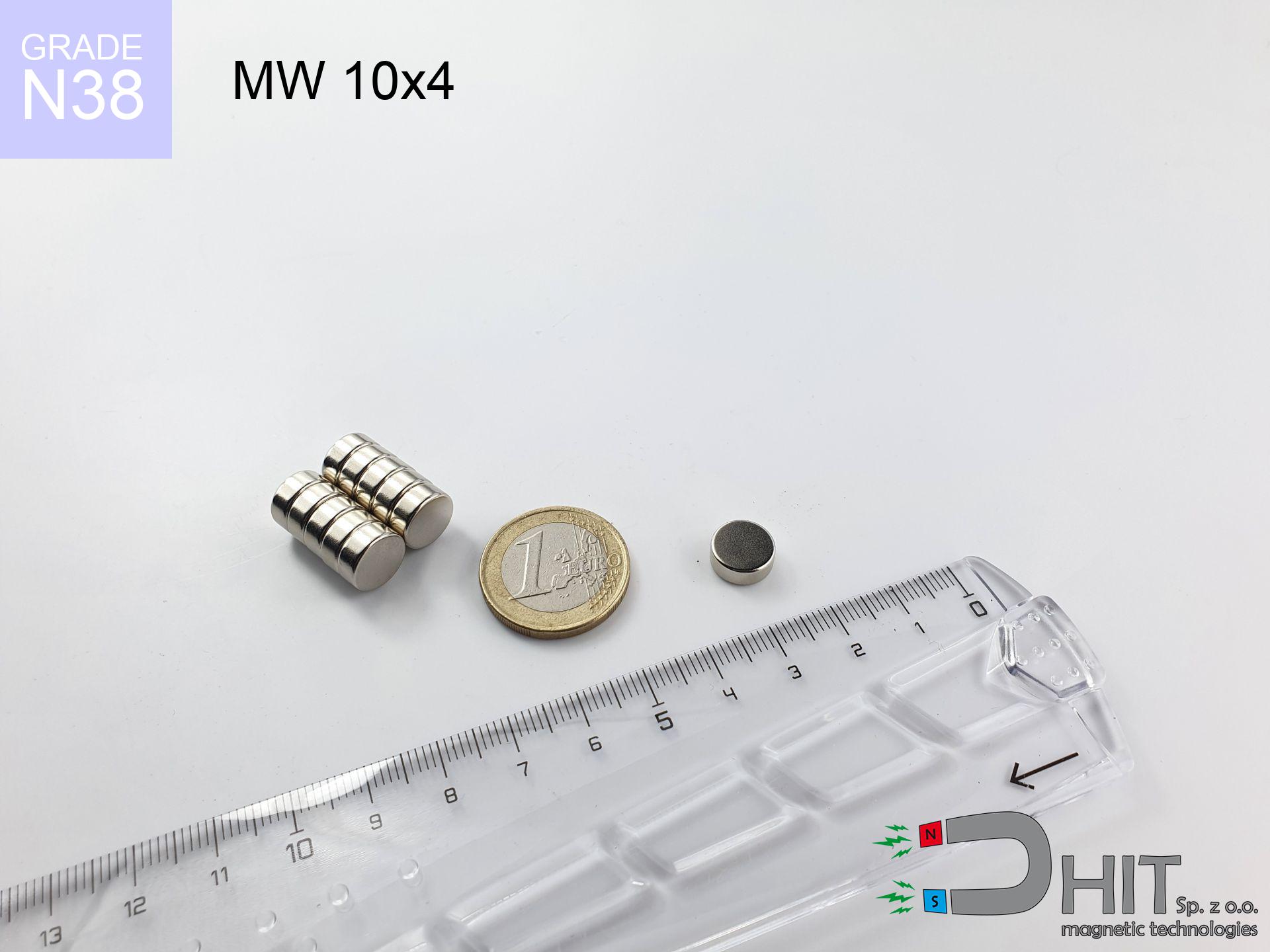
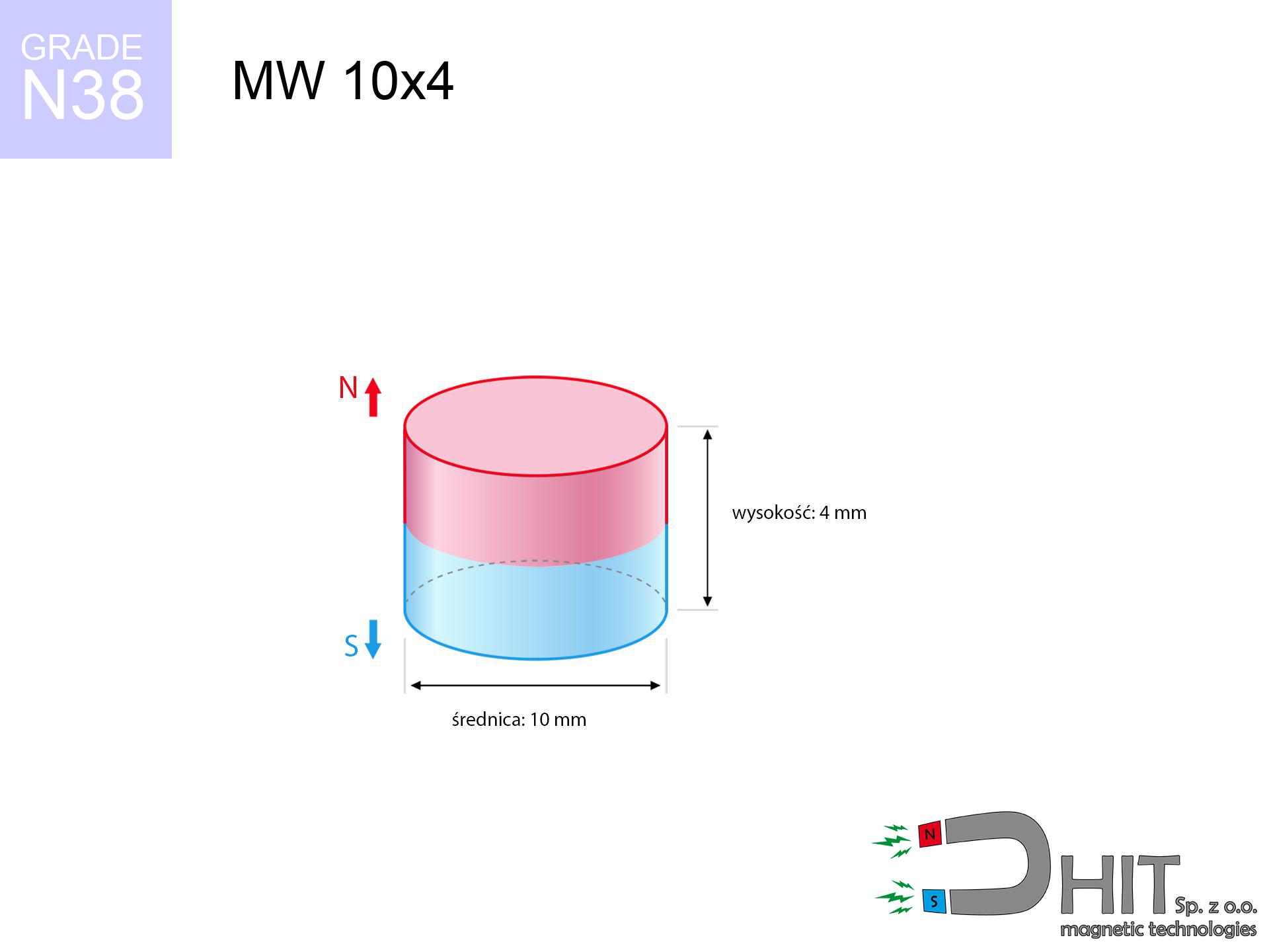
MW 10x4 / N38 - cylindrical magnet
cylindrical magnet
Catalog no 010010
GTIN/EAN: 5906301810094
Diameter Ø
10 mm [±0,1 mm]
Height
4 mm [±0,1 mm]
Weight
2.36 g
Magnetization Direction
↑ axial
Load capacity
2.80 kg / 27.42 N
Magnetic Induction
386.91 mT / 3869 Gs
Coating
[NiCuNi] Nickel
1.021 ZŁ with VAT / pcs + price for transport
0.830 ZŁ net + 23% VAT / pcs
bulk discounts:
Need more?
Call us
+48 22 499 98 98
or let us know via
form
the contact section.
Specifications as well as shape of a magnet can be calculated using our
modular calculator.
Orders placed before 14:00 will be shipped the same business day.
Technical details - MW 10x4 / N38 - cylindrical magnet
Specification / characteristics - MW 10x4 / N38 - cylindrical magnet
| properties | values |
|---|---|
| Cat. no. | 010010 |
| GTIN/EAN | 5906301810094 |
| Production/Distribution | Dhit sp. z o.o. |
| Country of origin | Poland / China / Germany |
| Customs code | 85059029 |
| Diameter Ø | 10 mm [±0,1 mm] |
| Height | 4 mm [±0,1 mm] |
| Weight | 2.36 g |
| Magnetization Direction | ↑ axial |
| Load capacity ~ ? | 2.80 kg / 27.42 N |
| Magnetic Induction ~ ? | 386.91 mT / 3869 Gs |
| Coating | [NiCuNi] Nickel |
| Manufacturing Tolerance | ±0.1 mm |
Magnetic properties of material N38
| properties | values | units |
|---|---|---|
| remenance Br [min. - max.] ? | 12.2-12.6 | kGs |
| remenance Br [min. - max.] ? | 1220-1260 | mT |
| coercivity bHc ? | 10.8-11.5 | kOe |
| coercivity bHc ? | 860-915 | kA/m |
| actual internal force iHc | ≥ 12 | kOe |
| actual internal force iHc | ≥ 955 | kA/m |
| energy density [min. - max.] ? | 36-38 | BH max MGOe |
| energy density [min. - max.] ? | 287-303 | BH max KJ/m |
| max. temperature ? | ≤ 80 | °C |
Physical properties of sintered neodymium magnets Nd2Fe14B at 20°C
| properties | values | units |
|---|---|---|
| Vickers hardness | ≥550 | Hv |
| Density | ≥7.4 | g/cm3 |
| Curie Temperature TC | 312 - 380 | °C |
| Curie Temperature TF | 593 - 716 | °F |
| Specific resistance | 150 | μΩ⋅cm |
| Bending strength | 250 | MPa |
| Compressive strength | 1000~1100 | MPa |
| Thermal expansion parallel (∥) to orientation (M) | (3-4) x 10-6 | °C-1 |
| Thermal expansion perpendicular (⊥) to orientation (M) | -(1-3) x 10-6 | °C-1 |
| Young's modulus | 1.7 x 10⁴ | kg/mm² |
Physical analysis of the product - report
Presented data represent the outcome of a physical analysis. Values rely on models for the class Nd2Fe14B. Operational parameters might slightly differ from theoretical values. Please consider these calculations as a reference point during assembly planning.
Table 1: Static force (force vs gap) - power drop
MW 10x4 / N38
| Distance (mm) | Induction (Gauss) / mT | Pull Force (kg/lbs/g/N) | Risk Status |
|---|---|---|---|
| 0 mm |
3867 Gs
386.7 mT
|
2.80 kg / 6.17 pounds
2800.0 g / 27.5 N
|
warning |
| 1 mm |
3168 Gs
316.8 mT
|
1.88 kg / 4.14 pounds
1879.8 g / 18.4 N
|
weak grip |
| 2 mm |
2460 Gs
246.0 mT
|
1.13 kg / 2.50 pounds
1133.7 g / 11.1 N
|
weak grip |
| 3 mm |
1855 Gs
185.5 mT
|
0.64 kg / 1.42 pounds
644.6 g / 6.3 N
|
weak grip |
| 5 mm |
1036 Gs
103.6 mT
|
0.20 kg / 0.44 pounds
200.9 g / 2.0 N
|
weak grip |
| 10 mm |
293 Gs
29.3 mT
|
0.02 kg / 0.04 pounds
16.1 g / 0.2 N
|
weak grip |
| 15 mm |
114 Gs
11.4 mT
|
0.00 kg / 0.01 pounds
2.4 g / 0.0 N
|
weak grip |
| 20 mm |
55 Gs
5.5 mT
|
0.00 kg / 0.00 pounds
0.6 g / 0.0 N
|
weak grip |
| 30 mm |
18 Gs
1.8 mT
|
0.00 kg / 0.00 pounds
0.1 g / 0.0 N
|
weak grip |
| 50 mm |
4 Gs
0.4 mT
|
0.00 kg / 0.00 pounds
0.0 g / 0.0 N
|
weak grip |
Table 2: Sliding force (vertical surface)
MW 10x4 / N38
| Distance (mm) | Friction coefficient | Pull Force (kg/lbs/g/N) |
|---|---|---|
| 0 mm | Stal (~0.2) |
0.56 kg / 1.23 pounds
560.0 g / 5.5 N
|
| 1 mm | Stal (~0.2) |
0.38 kg / 0.83 pounds
376.0 g / 3.7 N
|
| 2 mm | Stal (~0.2) |
0.23 kg / 0.50 pounds
226.0 g / 2.2 N
|
| 3 mm | Stal (~0.2) |
0.13 kg / 0.28 pounds
128.0 g / 1.3 N
|
| 5 mm | Stal (~0.2) |
0.04 kg / 0.09 pounds
40.0 g / 0.4 N
|
| 10 mm | Stal (~0.2) |
0.00 kg / 0.01 pounds
4.0 g / 0.0 N
|
| 15 mm | Stal (~0.2) |
0.00 kg / 0.00 pounds
0.0 g / 0.0 N
|
| 20 mm | Stal (~0.2) |
0.00 kg / 0.00 pounds
0.0 g / 0.0 N
|
| 30 mm | Stal (~0.2) |
0.00 kg / 0.00 pounds
0.0 g / 0.0 N
|
| 50 mm | Stal (~0.2) |
0.00 kg / 0.00 pounds
0.0 g / 0.0 N
|
Table 3: Vertical assembly (sliding) - vertical pull
MW 10x4 / N38
| Surface type | Friction coefficient / % Mocy | Max load (kg/lbs/g/N) |
|---|---|---|
| Raw steel |
µ = 0.3
30% Nominalnej Siły
|
0.84 kg / 1.85 pounds
840.0 g / 8.2 N
|
| Painted steel (standard) |
µ = 0.2
20% Nominalnej Siły
|
0.56 kg / 1.23 pounds
560.0 g / 5.5 N
|
| Oily/slippery steel |
µ = 0.1
10% Nominalnej Siły
|
0.28 kg / 0.62 pounds
280.0 g / 2.7 N
|
| Magnet with anti-slip rubber |
µ = 0.5
50% Nominalnej Siły
|
1.40 kg / 3.09 pounds
1400.0 g / 13.7 N
|
Table 4: Steel thickness (saturation) - sheet metal selection
MW 10x4 / N38
| Steel thickness (mm) | % power | Real pull force (kg/lbs/g/N) |
|---|---|---|
| 0.5 mm |
|
0.28 kg / 0.62 pounds
280.0 g / 2.7 N
|
| 1 mm |
|
0.70 kg / 1.54 pounds
700.0 g / 6.9 N
|
| 2 mm |
|
1.40 kg / 3.09 pounds
1400.0 g / 13.7 N
|
| 3 mm |
|
2.10 kg / 4.63 pounds
2100.0 g / 20.6 N
|
| 5 mm |
|
2.80 kg / 6.17 pounds
2800.0 g / 27.5 N
|
| 10 mm |
|
2.80 kg / 6.17 pounds
2800.0 g / 27.5 N
|
| 11 mm |
|
2.80 kg / 6.17 pounds
2800.0 g / 27.5 N
|
| 12 mm |
|
2.80 kg / 6.17 pounds
2800.0 g / 27.5 N
|
Table 5: Thermal resistance (stability) - power drop
MW 10x4 / N38
| Ambient temp. (°C) | Power loss | Remaining pull (kg/lbs/g/N) | Status |
|---|---|---|---|
| 20 °C | 0.0% |
2.80 kg / 6.17 pounds
2800.0 g / 27.5 N
|
OK |
| 40 °C | -2.2% |
2.74 kg / 6.04 pounds
2738.4 g / 26.9 N
|
OK |
| 60 °C | -4.4% |
2.68 kg / 5.90 pounds
2676.8 g / 26.3 N
|
|
| 80 °C | -6.6% |
2.62 kg / 5.77 pounds
2615.2 g / 25.7 N
|
|
| 100 °C | -28.8% |
1.99 kg / 4.40 pounds
1993.6 g / 19.6 N
|
Table 6: Two magnets (attraction) - field range
MW 10x4 / N38
| Gap (mm) | Attraction (kg/lbs) (N-S) | Shear Force (kg/lbs/g/N) | Repulsion (kg/lbs) (N-N) |
|---|---|---|---|
| 0 mm |
7.24 kg / 15.96 pounds
5 247 Gs
|
1.09 kg / 2.39 pounds
1086 g / 10.7 N
|
N/A |
| 1 mm |
6.04 kg / 13.31 pounds
7 061 Gs
|
0.91 kg / 2.00 pounds
905 g / 8.9 N
|
5.43 kg / 11.98 pounds
~0 Gs
|
| 2 mm |
4.86 kg / 10.71 pounds
6 336 Gs
|
0.73 kg / 1.61 pounds
729 g / 7.2 N
|
4.37 kg / 9.64 pounds
~0 Gs
|
| 3 mm |
3.81 kg / 8.41 pounds
5 612 Gs
|
0.57 kg / 1.26 pounds
572 g / 5.6 N
|
3.43 kg / 7.56 pounds
~0 Gs
|
| 5 mm |
2.22 kg / 4.90 pounds
4 283 Gs
|
0.33 kg / 0.73 pounds
333 g / 3.3 N
|
2.00 kg / 4.41 pounds
~0 Gs
|
| 10 mm |
0.52 kg / 1.15 pounds
2 071 Gs
|
0.08 kg / 0.17 pounds
78 g / 0.8 N
|
0.47 kg / 1.03 pounds
~0 Gs
|
| 20 mm |
0.04 kg / 0.09 pounds
587 Gs
|
0.01 kg / 0.01 pounds
6 g / 0.1 N
|
0.04 kg / 0.08 pounds
~0 Gs
|
| 50 mm |
0.00 kg / 0.00 pounds
61 Gs
|
0.00 kg / 0.00 pounds
0 g / 0.0 N
|
0.00 kg / 0.00 pounds
~0 Gs
|
| 60 mm |
0.00 kg / 0.00 pounds
37 Gs
|
0.00 kg / 0.00 pounds
0 g / 0.0 N
|
0.00 kg / 0.00 pounds
~0 Gs
|
| 70 mm |
0.00 kg / 0.00 pounds
24 Gs
|
0.00 kg / 0.00 pounds
0 g / 0.0 N
|
0.00 kg / 0.00 pounds
~0 Gs
|
| 80 mm |
0.00 kg / 0.00 pounds
16 Gs
|
0.00 kg / 0.00 pounds
0 g / 0.0 N
|
0.00 kg / 0.00 pounds
~0 Gs
|
| 90 mm |
0.00 kg / 0.00 pounds
12 Gs
|
0.00 kg / 0.00 pounds
0 g / 0.0 N
|
0.00 kg / 0.00 pounds
~0 Gs
|
| 100 mm |
0.00 kg / 0.00 pounds
9 Gs
|
0.00 kg / 0.00 pounds
0 g / 0.0 N
|
0.00 kg / 0.00 pounds
~0 Gs
|
Table 7: Hazards (electronics) - precautionary measures
MW 10x4 / N38
| Object / Device | Limit (Gauss) / mT | Safe distance |
|---|---|---|
| Pacemaker | 5 Gs (0.5 mT) | 5.0 cm |
| Hearing aid | 10 Gs (1.0 mT) | 4.0 cm |
| Timepiece | 20 Gs (2.0 mT) | 3.0 cm |
| Mobile device | 40 Gs (4.0 mT) | 2.5 cm |
| Remote | 50 Gs (5.0 mT) | 2.5 cm |
| Payment card | 400 Gs (40.0 mT) | 1.0 cm |
| HDD hard drive | 600 Gs (60.0 mT) | 1.0 cm |
Table 8: Dynamics (kinetic energy) - collision effects
MW 10x4 / N38
| Start from (mm) | Speed (km/h) | Energy (J) | Predicted outcome |
|---|---|---|---|
| 10 mm |
34.86 km/h
(9.68 m/s)
|
0.11 J | |
| 30 mm |
60.17 km/h
(16.71 m/s)
|
0.33 J | |
| 50 mm |
77.68 km/h
(21.58 m/s)
|
0.55 J | |
| 100 mm |
109.85 km/h
(30.51 m/s)
|
1.10 J |
Table 9: Corrosion resistance
MW 10x4 / N38
| Technical parameter | Value / Description |
|---|---|
| Coating type | [NiCuNi] Nickel |
| Layer structure | Nickel - Copper - Nickel |
| Layer thickness | 10-20 µm |
| Salt spray test (SST) ? | 24 h |
| Recommended environment | Indoors only (dry) |
Table 10: Construction data (Pc)
MW 10x4 / N38
| Parameter | Value | SI Unit / Description |
|---|---|---|
| Magnetic Flux | 3 142 Mx | 31.4 µWb |
| Pc Coefficient | 0.50 | Low (Flat) |
Table 11: Underwater work (magnet fishing)
MW 10x4 / N38
| Environment | Effective steel pull | Effect |
|---|---|---|
| Air (land) | 2.80 kg | Standard |
| Water (riverbed) |
3.21 kg
(+0.41 kg buoyancy gain)
|
+14.5% |
1. Shear force
*Caution: On a vertical surface, the magnet holds merely ~20% of its max power.
2. Steel thickness impact
*Thin steel (e.g. 0.5mm PC case) drastically weakens the holding force.
3. Power loss vs temp
*For N38 grade, the critical limit is 80°C.
4. Demagnetization curve and operating point (B-H)
chart generated for the permeance coefficient Pc (Permeance Coefficient) = 0.50
This simulation demonstrates the magnetic stability of the selected magnet under specific geometric conditions. The solid red line represents the demagnetization curve (material potential), while the dashed blue line is the load line based on the magnet's geometry. The Pc (Permeance Coefficient), also known as the load line slope, is a dimensionless value that describes the relationship between the magnet's shape and its magnetic stability. The intersection of these two lines (the black dot) is the operating point — it determines the actual magnetic flux density generated by the magnet in this specific configuration. A higher Pc value means the magnet is more 'slender' (tall relative to its area), resulting in a higher operating point and better resistance to irreversible demagnetization caused by external fields or temperature. A value of 0.42 is relatively low (typical for flat magnets), meaning the operating point is closer to the 'knee' of the curve — caution is advised when operating at temperatures near the maximum limit to avoid strength loss.
Chemical composition
| iron (Fe) | 64% – 68% |
| neodymium (Nd) | 29% – 32% |
| boron (B) | 1.1% – 1.2% |
| dysprosium (Dy) | 0.5% – 2.0% |
| coating (Ni-Cu-Ni) | < 0.05% |
Environmental data
| recyclability (EoL) | 100% |
| recycled raw materials | ~10% (pre-cons) |
| carbon footprint | low / zredukowany |
| waste code (EWC) | 16 02 16 |
Other proposals

![SM 32x300 [2xM8] / N52 - magnetic separator](https://cdn3.dhit.pl/graphics/products/sm-32x300-2xm8-luf.jpg "SM 32x300 [2xM8] / N52 - magnetic separator")

![SM 32x250 [2xM8] / N52 - magnetic separator](https://cdn3.dhit.pl/graphics/products/sm-32x250-2xm8-guf.jpg "SM 32x250 [2xM8] / N52 - magnetic separator")
Pros and cons of rare earth magnets.
Strengths
- They have unchanged lifting capacity, and over more than 10 years their attraction force decreases symbolically – ~1% (according to theory),
- They have excellent resistance to weakening of magnetic properties due to opposing magnetic fields,
- By using a shiny layer of nickel, the element acquires an elegant look,
- Neodymium magnets generate maximum magnetic induction on a contact point, which allows for strong attraction,
- Due to their durability and thermal resistance, neodymium magnets can operate (depending on the shape) even at high temperatures reaching 230°C or more...
- Possibility of exact machining and modifying to individual requirements,
- Versatile presence in high-tech industry – they are utilized in HDD drives, motor assemblies, advanced medical instruments, and complex engineering applications.
- Relatively small size with high pulling force – neodymium magnets offer impressive pulling force in compact dimensions, which allows their use in small systems
Cons
- They are prone to damage upon heavy impacts. To avoid cracks, it is worth protecting magnets using a steel holder. Such protection not only shields the magnet but also increases its resistance to damage
- Neodymium magnets lose their force under the influence of heating. As soon as 80°C is exceeded, many of them start losing their power. Therefore, we recommend our special magnets marked [AH], which maintain durability even at temperatures up to 230°C
- Magnets exposed to a humid environment can rust. Therefore when using outdoors, we suggest using water-impermeable magnets made of rubber, plastic or other material protecting against moisture
- Limited ability of producing threads in the magnet and complicated forms - recommended is a housing - magnetic holder.
- Potential hazard resulting from small fragments of magnets are risky, in case of ingestion, which is particularly important in the context of child health protection. Furthermore, small elements of these products can complicate diagnosis medical after entering the body.
- Due to expensive raw materials, their price is relatively high,
Pull force analysis
Optimal lifting capacity of a neodymium magnet – what contributes to it?
- using a sheet made of high-permeability steel, functioning as a magnetic yoke
- possessing a thickness of min. 10 mm to avoid saturation
- characterized by even structure
- under conditions of no distance (surface-to-surface)
- under vertical force direction (90-degree angle)
- at standard ambient temperature
Practical aspects of lifting capacity – factors
- Gap between surfaces – every millimeter of distance (caused e.g. by veneer or dirt) drastically reduces the magnet efficiency, often by half at just 0.5 mm.
- Angle of force application – maximum parameter is available only during perpendicular pulling. The resistance to sliding of the magnet along the surface is typically several times lower (approx. 1/5 of the lifting capacity).
- Metal thickness – thin material does not allow full use of the magnet. Part of the magnetic field passes through the material instead of converting into lifting capacity.
- Material type – ideal substrate is high-permeability steel. Hardened steels may have worse magnetic properties.
- Surface condition – smooth surfaces ensure maximum contact, which improves field saturation. Uneven metal weaken the grip.
- Temperature influence – high temperature weakens magnetic field. Exceeding the limit temperature can permanently damage the magnet.
Lifting capacity testing was carried out on a smooth plate of suitable thickness, under a perpendicular pulling force, however under attempts to slide the magnet the holding force is lower. Moreover, even a small distance between the magnet and the plate reduces the holding force.
Warnings
Dust is flammable
Fire warning: Rare earth powder is explosive. Avoid machining magnets without safety gear as this risks ignition.
Keep away from electronics
Be aware: rare earth magnets produce a field that disrupts sensitive sensors. Keep a safe distance from your mobile, device, and navigation systems.
Medical interference
Medical warning: Strong magnets can deactivate pacemakers and defibrillators. Stay away if you have electronic implants.
Metal Allergy
Nickel alert: The nickel-copper-nickel coating contains nickel. If redness appears, cease working with magnets and wear gloves.
Thermal limits
Do not overheat. NdFeB magnets are susceptible to heat. If you need resistance above 80°C, ask us about HT versions (H, SH, UH).
Electronic devices
Do not bring magnets near a wallet, laptop, or TV. The magnetism can destroy these devices and wipe information from cards.
Product not for children
Always store magnets away from children. Risk of swallowing is high, and the effects of magnets clamping inside the body are very dangerous.
Respect the power
Handle with care. Rare earth magnets act from a long distance and connect with huge force, often quicker than you can react.
Bodily injuries
Watch your fingers. Two powerful magnets will snap together immediately with a force of massive weight, destroying anything in their path. Exercise extreme caution!
Shattering risk
Beware of splinters. Magnets can explode upon uncontrolled impact, ejecting shards into the air. We recommend safety glasses.
Tabela kosztu i czasu dostawy
Płatność przed wysyłką:

GLS kurier
Przesyłka będzie u Ciebie za 2-3 dni
14.99 ZŁ

InPost Paczkomaty 24/7
Przesyłka będzie u Ciebie za 1-2 dni
12.30 ZŁ
Płatność przy odbiorze (pobranie):
GLS kurier
Przesyłka będzie u Ciebie za 1-2 dni
23.00 ZŁ
Rate the product
Your rating