

MW 22x6 / N38 - cylindrical magnet
cylindrical magnet
Catalog no 010047
GTIN/EAN: 5906301810469
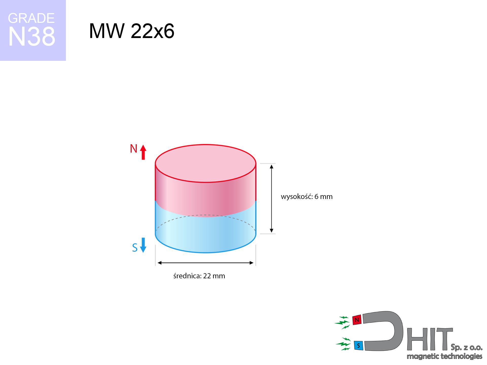
Diameter Ø
22 mm [±0,1 mm]
Height
6 mm [±0,1 mm]
Weight
17.11 g
Magnetization Direction
↑ axial
Load capacity
9.33 kg / 91.51 N
Magnetic Induction
296.78 mT / 2968 Gs
Coating
[NiCuNi] Nickel
6.11 ZŁ with VAT / pcs + price for transport
4.97 ZŁ net + 23% VAT / pcs
bulk discounts:
Need more?
Pick up the phone and ask
+48 22 499 98 98
otherwise contact us through
inquiry form
our website.
Specifications and form of magnetic components can be tested using our
force calculator.
Orders placed before 14:00 will be shipped the same business day.
Technical specification - MW 22x6 / N38 - cylindrical magnet
Specification / characteristics - MW 22x6 / N38 - cylindrical magnet
| properties | values |
|---|---|
| Cat. no. | 010047 |
| GTIN/EAN | 5906301810469 |
| Production/Distribution | Dhit sp. z o.o. |
| Country of origin | Poland / China / Germany |
| Customs code | 85059029 |
| Diameter Ø | 22 mm [±0,1 mm] |
| Height | 6 mm [±0,1 mm] |
| Weight | 17.11 g |
| Magnetization Direction | ↑ axial |
| Load capacity ~ ? | 9.33 kg / 91.51 N |
| Magnetic Induction ~ ? | 296.78 mT / 2968 Gs |
| Coating | [NiCuNi] Nickel |
| Manufacturing Tolerance | ±0.1 mm |
Magnetic properties of material N38
| properties | values | units |
|---|---|---|
| remenance Br [min. - max.] ? | 12.2-12.6 | kGs |
| remenance Br [min. - max.] ? | 1220-1260 | mT |
| coercivity bHc ? | 10.8-11.5 | kOe |
| coercivity bHc ? | 860-915 | kA/m |
| actual internal force iHc | ≥ 12 | kOe |
| actual internal force iHc | ≥ 955 | kA/m |
| energy density [min. - max.] ? | 36-38 | BH max MGOe |
| energy density [min. - max.] ? | 287-303 | BH max KJ/m |
| max. temperature ? | ≤ 80 | °C |
Physical properties of sintered neodymium magnets Nd2Fe14B at 20°C
| properties | values | units |
|---|---|---|
| Vickers hardness | ≥550 | Hv |
| Density | ≥7.4 | g/cm3 |
| Curie Temperature TC | 312 - 380 | °C |
| Curie Temperature TF | 593 - 716 | °F |
| Specific resistance | 150 | μΩ⋅cm |
| Bending strength | 250 | MPa |
| Compressive strength | 1000~1100 | MPa |
| Thermal expansion parallel (∥) to orientation (M) | (3-4) x 10-6 | °C-1 |
| Thermal expansion perpendicular (⊥) to orientation (M) | -(1-3) x 10-6 | °C-1 |
| Young's modulus | 1.7 x 10⁴ | kg/mm² |
Physical analysis of the assembly - data
The following data are the outcome of a engineering calculation. Results are based on models for the material Nd2Fe14B. Actual conditions may differ from theoretical values. Use these calculations as a reference point during assembly planning.
Table 1: Static pull force (force vs gap) - power drop
MW 22x6 / N38
| Distance (mm) | Induction (Gauss) / mT | Pull Force (kg/lbs/g/N) | Risk Status |
|---|---|---|---|
| 0 mm |
2967 Gs
296.7 mT
|
9.33 kg / 20.57 pounds
9330.0 g / 91.5 N
|
strong |
| 1 mm |
2767 Gs
276.7 mT
|
8.12 kg / 17.89 pounds
8116.0 g / 79.6 N
|
strong |
| 2 mm |
2538 Gs
253.8 mT
|
6.82 kg / 15.05 pounds
6824.4 g / 66.9 N
|
strong |
| 3 mm |
2295 Gs
229.5 mT
|
5.58 kg / 12.30 pounds
5580.8 g / 54.7 N
|
strong |
| 5 mm |
1818 Gs
181.8 mT
|
3.50 kg / 7.73 pounds
3504.7 g / 34.4 N
|
strong |
| 10 mm |
938 Gs
93.8 mT
|
0.93 kg / 2.06 pounds
933.4 g / 9.2 N
|
safe |
| 15 mm |
492 Gs
49.2 mT
|
0.26 kg / 0.57 pounds
257.0 g / 2.5 N
|
safe |
| 20 mm |
277 Gs
27.7 mT
|
0.08 kg / 0.18 pounds
81.6 g / 0.8 N
|
safe |
| 30 mm |
108 Gs
10.8 mT
|
0.01 kg / 0.03 pounds
12.4 g / 0.1 N
|
safe |
| 50 mm |
29 Gs
2.9 mT
|
0.00 kg / 0.00 pounds
0.9 g / 0.0 N
|
safe |
Table 2: Shear capacity (wall)
MW 22x6 / N38
| Distance (mm) | Friction coefficient | Pull Force (kg/lbs/g/N) |
|---|---|---|
| 0 mm | Stal (~0.2) |
1.87 kg / 4.11 pounds
1866.0 g / 18.3 N
|
| 1 mm | Stal (~0.2) |
1.62 kg / 3.58 pounds
1624.0 g / 15.9 N
|
| 2 mm | Stal (~0.2) |
1.36 kg / 3.01 pounds
1364.0 g / 13.4 N
|
| 3 mm | Stal (~0.2) |
1.12 kg / 2.46 pounds
1116.0 g / 10.9 N
|
| 5 mm | Stal (~0.2) |
0.70 kg / 1.54 pounds
700.0 g / 6.9 N
|
| 10 mm | Stal (~0.2) |
0.19 kg / 0.41 pounds
186.0 g / 1.8 N
|
| 15 mm | Stal (~0.2) |
0.05 kg / 0.11 pounds
52.0 g / 0.5 N
|
| 20 mm | Stal (~0.2) |
0.02 kg / 0.04 pounds
16.0 g / 0.2 N
|
| 30 mm | Stal (~0.2) |
0.00 kg / 0.00 pounds
2.0 g / 0.0 N
|
| 50 mm | Stal (~0.2) |
0.00 kg / 0.00 pounds
0.0 g / 0.0 N
|
Table 3: Vertical assembly (sliding) - vertical pull
MW 22x6 / N38
| Surface type | Friction coefficient / % Mocy | Max load (kg/lbs/g/N) |
|---|---|---|
| Raw steel |
µ = 0.3
30% Nominalnej Siły
|
2.80 kg / 6.17 pounds
2799.0 g / 27.5 N
|
| Painted steel (standard) |
µ = 0.2
20% Nominalnej Siły
|
1.87 kg / 4.11 pounds
1866.0 g / 18.3 N
|
| Oily/slippery steel |
µ = 0.1
10% Nominalnej Siły
|
0.93 kg / 2.06 pounds
933.0 g / 9.2 N
|
| Magnet with anti-slip rubber |
µ = 0.5
50% Nominalnej Siły
|
4.67 kg / 10.28 pounds
4665.0 g / 45.8 N
|
Table 4: Material efficiency (substrate influence) - sheet metal selection
MW 22x6 / N38
| Steel thickness (mm) | % power | Real pull force (kg/lbs/g/N) |
|---|---|---|
| 0.5 mm |
|
0.93 kg / 2.06 pounds
933.0 g / 9.2 N
|
| 1 mm |
|
2.33 kg / 5.14 pounds
2332.5 g / 22.9 N
|
| 2 mm |
|
4.67 kg / 10.28 pounds
4665.0 g / 45.8 N
|
| 3 mm |
|
7.00 kg / 15.43 pounds
6997.5 g / 68.6 N
|
| 5 mm |
|
9.33 kg / 20.57 pounds
9330.0 g / 91.5 N
|
| 10 mm |
|
9.33 kg / 20.57 pounds
9330.0 g / 91.5 N
|
| 11 mm |
|
9.33 kg / 20.57 pounds
9330.0 g / 91.5 N
|
| 12 mm |
|
9.33 kg / 20.57 pounds
9330.0 g / 91.5 N
|
Table 5: Thermal resistance (material behavior) - thermal limit
MW 22x6 / N38
| Ambient temp. (°C) | Power loss | Remaining pull (kg/lbs/g/N) | Status |
|---|---|---|---|
| 20 °C | 0.0% |
9.33 kg / 20.57 pounds
9330.0 g / 91.5 N
|
OK |
| 40 °C | -2.2% |
9.12 kg / 20.12 pounds
9124.7 g / 89.5 N
|
OK |
| 60 °C | -4.4% |
8.92 kg / 19.66 pounds
8919.5 g / 87.5 N
|
|
| 80 °C | -6.6% |
8.71 kg / 19.21 pounds
8714.2 g / 85.5 N
|
|
| 100 °C | -28.8% |
6.64 kg / 14.65 pounds
6643.0 g / 65.2 N
|
Table 6: Magnet-Magnet interaction (attraction) - field range
MW 22x6 / N38
| Gap (mm) | Attraction (kg/lbs) (N-S) | Shear Strength (kg/lbs/g/N) | Repulsion (kg/lbs) (N-N) |
|---|---|---|---|
| 0 mm |
20.63 kg / 45.48 pounds
4 566 Gs
|
3.09 kg / 6.82 pounds
3095 g / 30.4 N
|
N/A |
| 1 mm |
19.34 kg / 42.63 pounds
5 745 Gs
|
2.90 kg / 6.40 pounds
2901 g / 28.5 N
|
17.40 kg / 38.37 pounds
~0 Gs
|
| 2 mm |
17.95 kg / 39.57 pounds
5 535 Gs
|
2.69 kg / 5.93 pounds
2692 g / 26.4 N
|
16.15 kg / 35.61 pounds
~0 Gs
|
| 3 mm |
16.52 kg / 36.42 pounds
5 310 Gs
|
2.48 kg / 5.46 pounds
2478 g / 24.3 N
|
14.87 kg / 32.78 pounds
~0 Gs
|
| 5 mm |
13.69 kg / 30.18 pounds
4 834 Gs
|
2.05 kg / 4.53 pounds
2053 g / 20.1 N
|
12.32 kg / 27.16 pounds
~0 Gs
|
| 10 mm |
7.75 kg / 17.09 pounds
3 637 Gs
|
1.16 kg / 2.56 pounds
1162 g / 11.4 N
|
6.97 kg / 15.38 pounds
~0 Gs
|
| 20 mm |
2.06 kg / 4.55 pounds
1 877 Gs
|
0.31 kg / 0.68 pounds
310 g / 3.0 N
|
1.86 kg / 4.10 pounds
~0 Gs
|
| 50 mm |
0.07 kg / 0.15 pounds
336 Gs
|
0.01 kg / 0.02 pounds
10 g / 0.1 N
|
0.06 kg / 0.13 pounds
~0 Gs
|
| 60 mm |
0.03 kg / 0.06 pounds
217 Gs
|
0.00 kg / 0.01 pounds
4 g / 0.0 N
|
0.02 kg / 0.05 pounds
~0 Gs
|
| 70 mm |
0.01 kg / 0.03 pounds
147 Gs
|
0.00 kg / 0.00 pounds
2 g / 0.0 N
|
0.01 kg / 0.03 pounds
~0 Gs
|
| 80 mm |
0.01 kg / 0.01 pounds
104 Gs
|
0.00 kg / 0.00 pounds
1 g / 0.0 N
|
0.00 kg / 0.00 pounds
~0 Gs
|
| 90 mm |
0.00 kg / 0.01 pounds
76 Gs
|
0.00 kg / 0.00 pounds
1 g / 0.0 N
|
0.00 kg / 0.00 pounds
~0 Gs
|
| 100 mm |
0.00 kg / 0.00 pounds
57 Gs
|
0.00 kg / 0.00 pounds
0 g / 0.0 N
|
0.00 kg / 0.00 pounds
~0 Gs
|
Table 7: Safety (HSE) (electronics) - warnings
MW 22x6 / N38
| Object / Device | Limit (Gauss) / mT | Safe distance |
|---|---|---|
| Pacemaker | 5 Gs (0.5 mT) | 9.5 cm |
| Hearing aid | 10 Gs (1.0 mT) | 7.5 cm |
| Timepiece | 20 Gs (2.0 mT) | 6.0 cm |
| Phone / Smartphone | 40 Gs (4.0 mT) | 4.5 cm |
| Car key | 50 Gs (5.0 mT) | 4.5 cm |
| Payment card | 400 Gs (40.0 mT) | 2.0 cm |
| HDD hard drive | 600 Gs (60.0 mT) | 1.5 cm |
Table 8: Dynamics (kinetic energy) - warning
MW 22x6 / N38
| Start from (mm) | Speed (km/h) | Energy (J) | Predicted outcome |
|---|---|---|---|
| 10 mm |
24.98 km/h
(6.94 m/s)
|
0.41 J | |
| 30 mm |
40.82 km/h
(11.34 m/s)
|
1.10 J | |
| 50 mm |
52.66 km/h
(14.63 m/s)
|
1.83 J | |
| 100 mm |
74.47 km/h
(20.69 m/s)
|
3.66 J |
Table 9: Coating parameters (durability)
MW 22x6 / N38
| Technical parameter | Value / Description |
|---|---|
| Coating type | [NiCuNi] Nickel |
| Layer structure | Nickel - Copper - Nickel |
| Layer thickness | 10-20 µm |
| Salt spray test (SST) ? | 24 h |
| Recommended environment | Indoors only (dry) |
Table 10: Construction data (Flux)
MW 22x6 / N38
| Parameter | Value | SI Unit / Description |
|---|---|---|
| Magnetic Flux | 12 337 Mx | 123.4 µWb |
| Pc Coefficient | 0.37 | Low (Flat) |
Table 11: Submerged application
MW 22x6 / N38
| Environment | Effective steel pull | Effect |
|---|---|---|
| Air (land) | 9.33 kg | Standard |
| Water (riverbed) |
10.68 kg
(+1.35 kg buoyancy gain)
|
+14.5% |
1. Wall mount (shear)
*Warning: On a vertical wall, the magnet retains merely a fraction of its max power.
2. Plate thickness effect
*Thin steel (e.g. 0.5mm PC case) significantly weakens the holding force.
3. Power loss vs temp
*For N38 material, the critical limit is 80°C.
4. Demagnetization curve and operating point (B-H)
chart generated for the permeance coefficient Pc (Permeance Coefficient) = 0.37
The chart above illustrates the magnetic characteristics of the material within the second quadrant of the hysteresis loop. The solid red line represents the demagnetization curve (material potential), while the dashed blue line is the load line based on the magnet's geometry. The Pc (Permeance Coefficient), also known as the load line slope, is a dimensionless value that describes the relationship between the magnet's shape and its magnetic stability. The intersection of these two lines (the black dot) is the operating point — it determines the actual magnetic flux density generated by the magnet in this specific configuration. A higher Pc value means the magnet is more 'slender' (tall relative to its area), resulting in a higher operating point and better resistance to irreversible demagnetization caused by external fields or temperature. A value of 0.42 is relatively low (typical for flat magnets), meaning the operating point is closer to the 'knee' of the curve — caution is advised when operating at temperatures near the maximum limit to avoid strength loss.
Chemical composition
| iron (Fe) | 64% – 68% |
| neodymium (Nd) | 29% – 32% |
| boron (B) | 1.1% – 1.2% |
| dysprosium (Dy) | 0.5% – 2.0% |
| coating (Ni-Cu-Ni) | < 0.05% |
Ecology and recycling (GPSR)
| recyclability (EoL) | 100% |
| recycled raw materials | ~10% (pre-cons) |
| carbon footprint | low / zredukowany |
| waste code (EWC) | 16 02 16 |
Other offers
![UMGZ 42x20x9 [M8] GZ / N38 - magnetic holder external thread](https://cdn3.dhit.pl/graphics/products/um-42x20x9-m8-gz-fof.jpg "UMGZ 42x20x9 [M8] GZ / N38 - magnetic holder external thread")


Advantages as well as disadvantages of neodymium magnets.
Benefits
- They virtually do not lose strength, because even after 10 years the performance loss is only ~1% (in laboratory conditions),
- They have excellent resistance to magnetism drop when exposed to opposing magnetic fields,
- In other words, due to the aesthetic layer of gold, the element becomes visually attractive,
- Magnets possess very high magnetic induction on the active area,
- Neodymium magnets are characterized by extremely high magnetic induction on the magnet surface and can function (depending on the form) even at a temperature of 230°C or more...
- Thanks to the possibility of accurate molding and customization to unique requirements, magnetic components can be modeled in a wide range of geometric configurations, which makes them more universal,
- Versatile presence in high-tech industry – they find application in data components, drive modules, precision medical tools, and complex engineering applications.
- Relatively small size with high pulling force – neodymium magnets offer high power in small dimensions, which enables their usage in miniature devices
Weaknesses
- At strong impacts they can break, therefore we advise placing them in steel cases. A metal housing provides additional protection against damage and increases the magnet's durability.
- Neodymium magnets decrease their power under the influence of heating. As soon as 80°C is exceeded, many of them start losing their force. Therefore, we recommend our special magnets marked [AH], which maintain durability even at temperatures up to 230°C
- Due to the susceptibility of magnets to corrosion in a humid environment, we advise using waterproof magnets made of rubber, plastic or other material resistant to moisture, when using outdoors
- Limited ability of making threads in the magnet and complicated shapes - recommended is casing - magnet mounting.
- Possible danger related to microscopic parts of magnets pose a threat, if swallowed, which is particularly important in the context of child safety. Furthermore, small components of these devices can disrupt the diagnostic process medical when they are in the body.
- Higher cost of purchase is a significant factor to consider compared to ceramic magnets, especially in budget applications
Pull force analysis
Detachment force of the magnet in optimal conditions – what contributes to it?
- on a base made of mild steel, perfectly concentrating the magnetic flux
- whose thickness is min. 10 mm
- characterized by smoothness
- without the slightest air gap between the magnet and steel
- under vertical force vector (90-degree angle)
- in neutral thermal conditions
Determinants of practical lifting force of a magnet
- Distance (betwixt the magnet and the plate), since even a very small clearance (e.g. 0.5 mm) can cause a reduction in force by up to 50% (this also applies to varnish, corrosion or dirt).
- Force direction – declared lifting capacity refers to detachment vertically. When attempting to slide, the magnet exhibits much less (typically approx. 20-30% of nominal force).
- Element thickness – for full efficiency, the steel must be sufficiently thick. Thin sheet limits the lifting capacity (the magnet "punches through" it).
- Plate material – mild steel gives the best results. Alloy steels decrease magnetic properties and holding force.
- Smoothness – full contact is obtained only on smooth steel. Any scratches and bumps reduce the real contact area, weakening the magnet.
- Temperature influence – high temperature weakens magnetic field. Too high temperature can permanently damage the magnet.
Lifting capacity testing was performed on a smooth plate of suitable thickness, under perpendicular forces, in contrast under shearing force the lifting capacity is smaller. Additionally, even a slight gap between the magnet and the plate reduces the lifting capacity.
Warnings
GPS Danger
A powerful magnetic field negatively affects the operation of magnetometers in phones and navigation systems. Maintain magnets close to a smartphone to prevent damaging the sensors.
Power loss in heat
Monitor thermal conditions. Exposing the magnet to high heat will destroy its properties and pulling force.
Handling guide
Exercise caution. Neodymium magnets act from a long distance and snap with huge force, often quicker than you can move away.
Bodily injuries
Protect your hands. Two powerful magnets will join immediately with a force of massive weight, destroying anything in their path. Exercise extreme caution!
Cards and drives
Intense magnetic fields can corrupt files on credit cards, hard drives, and other magnetic media. Maintain a gap of min. 10 cm.
Do not drill into magnets
Powder produced during cutting of magnets is self-igniting. Avoid drilling into magnets without proper cooling and knowledge.
Shattering risk
Watch out for shards. Magnets can fracture upon uncontrolled impact, ejecting shards into the air. Eye protection is mandatory.
ICD Warning
Medical warning: Neodymium magnets can turn off heart devices and defibrillators. Stay away if you have electronic implants.
Choking Hazard
Always store magnets away from children. Choking hazard is significant, and the consequences of magnets clamping inside the body are fatal.
Metal Allergy
Warning for allergy sufferers: The nickel-copper-nickel coating contains nickel. If redness appears, cease handling magnets and use protective gear.
Tabela kosztu i czasu dostawy
Płatność przed wysyłką:

GLS kurier
Przesyłka będzie u Ciebie za 2-3 dni
14.99 ZŁ

InPost Paczkomaty 24/7
Przesyłka będzie u Ciebie za 1-2 dni
12.30 ZŁ
Płatność przy odbiorze (pobranie):
GLS kurier
Przesyłka będzie u Ciebie za 1-2 dni
23.00 ZŁ
Rate the product
Your rating