

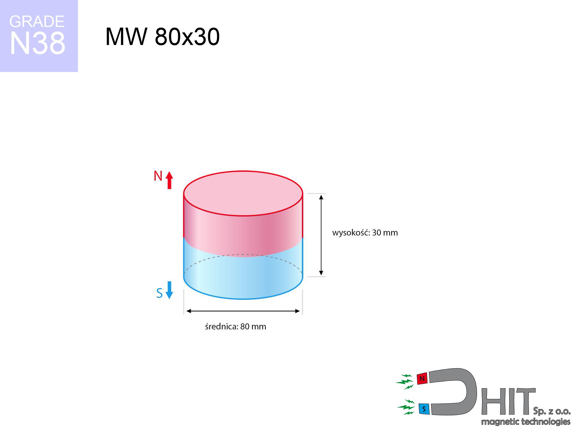
MW 80x30 / N38 - cylindrical magnet
cylindrical magnet
Catalog no 010100
GTIN/EAN: 5906301810995
- Diameter Ø
- 80 mm [±0,1 mm]
- Height
- 30 mm [±0,1 mm]
- Weight
- 1130.97 g
- Magnetization Direction
- ↑ axial
- Coating
- [NiCuNi] Nickel
415.00 zł with VAT / pcs + price for transport
337.40 zł net + 23% VAT / pcs
bulk discounts:
Need more?Engineering report for this magnet
Full PDF analysis: pull and shear force, effect of distance, temperature and plate thickness, safety distances and the demagnetization curve.
Contact us by phone
+48 22 499 98 98
or get in touch through
form
the contact section.
Lifting power as well as structure of neodymium magnets can be checked with our
magnetic mass calculator.
Order by 14:00 and we’ll ship today!
Physical properties - MW 80x30 / N38 - cylindrical magnet
Specification / characteristics - MW 80x30 / N38 - cylindrical magnet
| properties | values |
|---|---|
| Cat. no. | 010100 |
| GTIN/EAN | 5906301810995 |
| Production/Distribution | Dhit sp. z o.o. |
| Country of origin | Poland / China / Germany |
| Customs code | 85059029 |
| Diameter Ø | 80 mm [±0,1 mm] |
| Height | 30 mm [±0,1 mm] |
| Weight | 1130.97 g |
| Magnetization Direction | ↑ axial |
| Load capacity ~ ? | 170.64 kg / 1673.99 N |
| Magnetic Induction ~ ? | 371.95 mT / 3720 Gs |
| Coating | [NiCuNi] Nickel |
| Manufacturing Tolerance | ±0.1 mm |
Magnetic properties of material N38
| properties | values | units |
|---|---|---|
| remenance Br [min. - max.] ? | 12.2-12.6 | kGs |
| remenance Br [min. - max.] ? | 1220-1260 | mT |
| coercivity bHc ? | 10.8-11.5 | kOe |
| coercivity bHc ? | 860-915 | kA/m |
| actual internal force iHc | ≥ 12 | kOe |
| actual internal force iHc | ≥ 955 | kA/m |
| energy density [min. - max.] ? | 36-38 | BH max MGOe |
| energy density [min. - max.] ? | 287-303 | BH max KJ/m |
| max. temperature ? | ≤ 80 | °C |
Physical properties of sintered neodymium magnets Nd2Fe14B at 20°C
| properties | values | units |
|---|---|---|
| Vickers hardness | ≥550 | Hv |
| Density | ≥7.4 | g/cm3 |
| Curie Temperature TC | 312 - 380 | °C |
| Curie Temperature TF | 593 - 716 | °F |
| Specific resistance | 150 | μΩ⋅cm |
| Bending strength | 250 | MPa |
| Compressive strength | 1000~1100 | MPa |
| Thermal expansion parallel (∥) to orientation (M) | (3-4) x 10-6 | °C-1 |
| Thermal expansion perpendicular (⊥) to orientation (M) | -(1-3) x 10-6 | °C-1 |
| Young's modulus | 1.7 x 10⁴ | kg/mm² |
Engineering modeling of the assembly - technical parameters
These data represent the direct effect of a physical analysis. Results are based on algorithms for the material Nd2Fe14B. Actual conditions may differ from theoretical values. Use these data as a preliminary roadmap for designers.
Table 1: Static force (force vs gap) - characteristics
MW 80x30 / N38
| Distance (mm) | Induction (Gauss) / mT | Pull Force (kg/lbs/g/N) | Risk Status |
|---|---|---|---|
| 0 mm |
3719 Gs
371.9 mT
|
170.64 kg / 376.20 LBS
170640.0 g / 1674.0 N
|
critical level |
| 1 mm |
3643 Gs
364.3 mT
|
163.71 kg / 360.93 LBS
163714.9 g / 1606.0 N
|
critical level |
| 2 mm |
3563 Gs
356.3 mT
|
156.65 kg / 345.35 LBS
156647.8 g / 1536.7 N
|
critical level |
| 3 mm |
3482 Gs
348.2 mT
|
149.55 kg / 329.71 LBS
149554.1 g / 1467.1 N
|
critical level |
| 5 mm |
3314 Gs
331.4 mT
|
135.46 kg / 298.63 LBS
135457.0 g / 1328.8 N
|
critical level |
| 10 mm |
2880 Gs
288.0 mT
|
102.34 kg / 225.63 LBS
102343.3 g / 1004.0 N
|
critical level |
| 15 mm |
2457 Gs
245.7 mT
|
74.47 kg / 164.17 LBS
74468.4 g / 730.5 N
|
critical level |
| 20 mm |
2069 Gs
206.9 mT
|
52.79 kg / 116.38 LBS
52789.9 g / 517.9 N
|
critical level |
| 30 mm |
1439 Gs
143.9 mT
|
25.53 kg / 56.29 LBS
25534.0 g / 250.5 N
|
critical level |
| 50 mm |
704 Gs
70.4 mT
|
6.11 kg / 13.48 LBS
6115.0 g / 60.0 N
|
medium risk |
Table 2: Sliding force (wall)
MW 80x30 / N38
| Distance (mm) | Friction coefficient | Pull Force (kg/lbs/g/N) |
|---|---|---|
| 0 mm | Stal (~0.2) |
34.13 kg / 75.24 LBS
34128.0 g / 334.8 N
|
| 1 mm | Stal (~0.2) |
32.74 kg / 72.18 LBS
32742.0 g / 321.2 N
|
| 2 mm | Stal (~0.2) |
31.33 kg / 69.07 LBS
31330.0 g / 307.3 N
|
| 3 mm | Stal (~0.2) |
29.91 kg / 65.94 LBS
29910.0 g / 293.4 N
|
| 5 mm | Stal (~0.2) |
27.09 kg / 59.73 LBS
27092.0 g / 265.8 N
|
| 10 mm | Stal (~0.2) |
20.47 kg / 45.12 LBS
20468.0 g / 200.8 N
|
| 15 mm | Stal (~0.2) |
14.89 kg / 32.84 LBS
14894.0 g / 146.1 N
|
| 20 mm | Stal (~0.2) |
10.56 kg / 23.28 LBS
10558.0 g / 103.6 N
|
| 30 mm | Stal (~0.2) |
5.11 kg / 11.26 LBS
5106.0 g / 50.1 N
|
| 50 mm | Stal (~0.2) |
1.22 kg / 2.69 LBS
1222.0 g / 12.0 N
|
Table 3: Wall mounting (sliding) - vertical pull
MW 80x30 / N38
| Surface type | Friction coefficient / % Mocy | Max load (kg/lbs/g/N) |
|---|---|---|
| Raw steel |
µ = 0.3
30% Nominalnej Siły
|
51.19 kg / 112.86 LBS
51192.0 g / 502.2 N
|
| Painted steel (standard) |
µ = 0.2
20% Nominalnej Siły
|
34.13 kg / 75.24 LBS
34128.0 g / 334.8 N
|
| Oily/slippery steel |
µ = 0.1
10% Nominalnej Siły
|
17.06 kg / 37.62 LBS
17064.0 g / 167.4 N
|
| Magnet with anti-slip rubber |
µ = 0.5
50% Nominalnej Siły
|
85.32 kg / 188.10 LBS
85320.0 g / 837.0 N
|
Table 4: Steel thickness (saturation) - power losses
MW 80x30 / N38
| Steel thickness (mm) | % power | Real pull force (kg/lbs/g/N) |
|---|---|---|
| 0.5 mm |
|
5.69 kg / 12.54 LBS
5688.0 g / 55.8 N
|
| 1 mm |
|
14.22 kg / 31.35 LBS
14220.0 g / 139.5 N
|
| 2 mm |
|
28.44 kg / 62.70 LBS
28440.0 g / 279.0 N
|
| 3 mm |
|
42.66 kg / 94.05 LBS
42660.0 g / 418.5 N
|
| 5 mm |
|
71.10 kg / 156.75 LBS
71100.0 g / 697.5 N
|
| 10 mm |
|
142.20 kg / 313.50 LBS
142200.0 g / 1395.0 N
|
| 11 mm |
|
156.42 kg / 344.85 LBS
156420.0 g / 1534.5 N
|
| 12 mm |
|
170.64 kg / 376.20 LBS
170640.0 g / 1674.0 N
|
Table 5: Thermal resistance (stability) - resistance threshold
MW 80x30 / N38
| Ambient temp. (°C) | Power loss | Remaining pull (kg/lbs/g/N) | Status |
|---|---|---|---|
| 20 °C | 0.0% |
170.64 kg / 376.20 LBS
170640.0 g / 1674.0 N
|
OK |
| 40 °C | -2.2% |
166.89 kg / 367.92 LBS
166885.9 g / 1637.2 N
|
OK |
| 60 °C | -4.4% |
163.13 kg / 359.64 LBS
163131.8 g / 1600.3 N
|
|
| 80 °C | -6.6% |
159.38 kg / 351.37 LBS
159377.8 g / 1563.5 N
|
|
| 100 °C | -28.8% |
121.50 kg / 267.85 LBS
121495.7 g / 1191.9 N
|
Table 6: Magnet-Magnet interaction (repulsion) - forces in the system
MW 80x30 / N38
| Gap (mm) | Attraction (kg/lbs) (N-S) | Shear Force (kg/lbs/g/N) | Repulsion (kg/lbs) (N-N) |
|---|---|---|---|
| 0 mm |
428.66 kg / 945.03 LBS
5 157 Gs
|
64.30 kg / 141.76 LBS
64299 g / 630.8 N
|
N/A |
| 1 mm |
420.08 kg / 926.12 LBS
7 364 Gs
|
63.01 kg / 138.92 LBS
63012 g / 618.1 N
|
378.07 kg / 833.51 LBS
~0 Gs
|
| 2 mm |
411.26 kg / 906.68 LBS
7 286 Gs
|
61.69 kg / 136.00 LBS
61690 g / 605.2 N
|
370.14 kg / 816.01 LBS
~0 Gs
|
| 3 mm |
402.40 kg / 887.15 LBS
7 207 Gs
|
60.36 kg / 133.07 LBS
60360 g / 592.1 N
|
362.16 kg / 798.43 LBS
~0 Gs
|
| 5 mm |
384.60 kg / 847.90 LBS
7 046 Gs
|
57.69 kg / 127.19 LBS
57690 g / 565.9 N
|
346.14 kg / 763.11 LBS
~0 Gs
|
| 10 mm |
340.28 kg / 750.18 LBS
6 627 Gs
|
51.04 kg / 112.53 LBS
51042 g / 500.7 N
|
306.25 kg / 675.17 LBS
~0 Gs
|
| 20 mm |
257.09 kg / 566.80 LBS
5 761 Gs
|
38.56 kg / 85.02 LBS
38564 g / 378.3 N
|
231.38 kg / 510.12 LBS
~0 Gs
|
| 50 mm |
92.55 kg / 204.04 LBS
3 456 Gs
|
13.88 kg / 30.61 LBS
13883 g / 136.2 N
|
83.30 kg / 183.63 LBS
~0 Gs
|
| 60 mm |
64.14 kg / 141.41 LBS
2 877 Gs
|
9.62 kg / 21.21 LBS
9622 g / 94.4 N
|
57.73 kg / 127.27 LBS
~0 Gs
|
| 70 mm |
44.44 kg / 97.98 LBS
2 395 Gs
|
6.67 kg / 14.70 LBS
6666 g / 65.4 N
|
40.00 kg / 88.18 LBS
~0 Gs
|
| 80 mm |
30.93 kg / 68.19 LBS
1 998 Gs
|
4.64 kg / 10.23 LBS
4639 g / 45.5 N
|
27.84 kg / 61.37 LBS
~0 Gs
|
| 90 mm |
21.69 kg / 47.82 LBS
1 673 Gs
|
3.25 kg / 7.17 LBS
3254 g / 31.9 N
|
19.52 kg / 43.04 LBS
~0 Gs
|
| 100 mm |
15.36 kg / 33.87 LBS
1 408 Gs
|
2.30 kg / 5.08 LBS
2304 g / 22.6 N
|
13.83 kg / 30.48 LBS
~0 Gs
|
Table 7: Safety (HSE) (electronics) - precautionary measures
MW 80x30 / N38
| Object / Device | Limit (Gauss) / mT | Safe distance |
|---|---|---|
| Pacemaker | 5 Gs (0.5 mT) | 37.5 cm |
| Hearing aid | 10 Gs (1.0 mT) | 29.5 cm |
| Mechanical watch | 20 Gs (2.0 mT) | 23.0 cm |
| Phone / Smartphone | 40 Gs (4.0 mT) | 18.0 cm |
| Remote | 50 Gs (5.0 mT) | 16.5 cm |
| Payment card | 400 Gs (40.0 mT) | 7.0 cm |
| HDD hard drive | 600 Gs (60.0 mT) | 5.5 cm |
Table 8: Collisions (cracking risk) - warning
MW 80x30 / N38
| Start from (mm) | Speed (km/h) | Energy (J) | Predicted outcome |
|---|---|---|---|
| 10 mm |
17.48 km/h
(4.85 m/s)
|
13.32 J | |
| 30 mm |
23.66 km/h
(6.57 m/s)
|
24.42 J | |
| 50 mm |
24.91 km/h
(6.92 m/s)
|
27.06 J | |
| 100 mm |
25.32 km/h
(7.03 m/s)
|
27.98 J |
Table 9: Anti-corrosion coating durability
MW 80x30 / N38
| Technical parameter | Value / Description |
|---|---|
| Coating type | [NiCuNi] Nickel |
| Layer structure | Nickel - Copper - Nickel |
| Layer thickness | 10-20 µm |
| Salt spray test (SST) ? | 24 h |
| Recommended environment | Indoors only (dry) |
Table 10: Construction data (Flux)
MW 80x30 / N38
| Parameter | Value | SI Unit / Description |
|---|---|---|
| Magnetic Flux | 194 600 Mx | 1946.0 µWb |
| Pc Coefficient | 0.48 | Low (Flat) |
Table 11: Submerged application
MW 80x30 / N38
| Environment | Effective steel pull | Effect |
|---|---|---|
| Air (land) | 170.64 kg | Standard |
| Water (riverbed) |
195.38 kg
(+24.74 kg buoyancy gain)
|
+14.5% |
1. Shear force
*Note: On a vertical surface, the magnet retains merely a fraction of its max power.
2. Steel thickness impact
*Thin steel (e.g. computer case) severely reduces the holding force.
3. Thermal stability
*For N38 material, the critical limit is 80°C.
4. Demagnetization curve and operating point (B-H)
chart generated for the permeance coefficient Pc (Permeance Coefficient) = 0.48
The chart above illustrates the magnetic characteristics of the material within the second quadrant of the hysteresis loop. The solid red line represents the demagnetization curve (material potential), while the dashed blue line is the load line based on the magnet's geometry. The Pc (Permeance Coefficient), also known as the load line slope, is a dimensionless value that describes the relationship between the magnet's shape and its magnetic stability. The intersection of these two lines (the black dot) is the operating point — it determines the actual magnetic flux density generated by the magnet in this specific configuration. A higher Pc value means the magnet is more 'slender' (tall relative to its area), resulting in a higher operating point and better resistance to irreversible demagnetization caused by external fields or temperature. A value of 0.42 is relatively low (typical for flat magnets), meaning the operating point is closer to the 'knee' of the curve — caution is advised when operating at temperatures near the maximum limit to avoid strength loss.
Chemical composition
| iron (Fe) | 64% – 68% |
| neodymium (Nd) | 29% – 32% |
| boron (B) | 1.1% – 1.2% |
| dysprosium (Dy) | 0.5% – 2.0% |
| coating (Ni-Cu-Ni) | < 0.05% |
Environmental data
| recyclability (EoL) | 100% |
| recycled raw materials | ~10% (pre-cons) |
| carbon footprint | low / zredukowany |
| waste code (EWC) | 16 02 16 |
Other offers

![UI 45x13x6 [C321] / N38 - badge holder](https://cdn3.dhit.pl/graphics/products/ui45x13x6-c321-jic.jpg "UI 45x13x6 [C321] / N38 - badge holder")

![SM 32x400 [2xM8] / N52 - magnetic separator](https://cdn3.dhit.pl/graphics/products/sm-32x400-2xm8-led.jpg "SM 32x400 [2xM8] / N52 - magnetic separator")
Advantages and disadvantages of neodymium magnets.
Benefits
- They retain full power for nearly ten years – the loss is just ~1% (in theory),
- Magnets very well protect themselves against demagnetization caused by ambient magnetic noise,
- By applying a shiny layer of silver, the element gains an nice look,
- Neodymium magnets generate maximum magnetic induction on a their surface, which ensures high operational effectiveness,
- Thanks to resistance to high temperature, they are capable of working (depending on the shape) even at temperatures up to 230°C and higher...
- Possibility of precise creating as well as adapting to defined requirements,
- Fundamental importance in high-tech industry – they are utilized in magnetic memories, drive modules, precision medical tools, as well as multitasking production systems.
- Thanks to their power density, small magnets offer high operating force, in miniature format,
Cons
- To avoid cracks under impact, we recommend using special steel housings. Such a solution secures the magnet and simultaneously improves its durability.
- When exposed to high temperature, neodymium magnets suffer a drop in force. Often, when the temperature exceeds 80°C, their strength decreases (depending on the size and shape of the magnet). For those who need magnets for extreme conditions, we offer [AH] versions withstanding up to 230°C
- Magnets exposed to a humid environment can rust. Therefore during using outdoors, we recommend using water-impermeable magnets made of rubber, plastic or other material protecting against moisture
- Due to limitations in creating threads and complicated forms in magnets, we propose using a housing - magnetic mechanism.
- Health risk related to microscopic parts of magnets can be dangerous, if swallowed, which gains importance in the context of child health protection. Furthermore, small elements of these magnets can disrupt the diagnostic process medical after entering the body.
- High unit price – neodymium magnets cost more than other types of magnets (e.g. ferrite), which hinders application in large quantities
Pull force analysis
Maximum lifting capacity of the magnet – what it depends on?
- using a sheet made of mild steel, functioning as a magnetic yoke
- possessing a massiveness of at least 10 mm to avoid saturation
- with a surface perfectly flat
- under conditions of no distance (metal-to-metal)
- for force acting at a right angle (pull-off, not shear)
- in stable room temperature
Lifting capacity in practice – influencing factors
- Gap (betwixt the magnet and the metal), because even a microscopic distance (e.g. 0.5 mm) can cause a drastic drop in lifting capacity by up to 50% (this also applies to varnish, rust or dirt).
- Direction of force – highest force is available only during pulling at a 90° angle. The force required to slide of the magnet along the surface is standardly several times smaller (approx. 1/5 of the lifting capacity).
- Element thickness – to utilize 100% power, the steel must be sufficiently thick. Paper-thin metal restricts the lifting capacity (the magnet "punches through" it).
- Material type – ideal substrate is pure iron steel. Cast iron may generate lower lifting capacity.
- Surface condition – smooth surfaces guarantee perfect abutment, which improves force. Uneven metal weaken the grip.
- Heat – neodymium magnets have a sensitivity to temperature. When it is hot they lose power, and at low temperatures gain strength (up to a certain limit).
Lifting capacity testing was performed on a smooth plate of optimal thickness, under a perpendicular pulling force, however under attempts to slide the magnet the load capacity is reduced by as much as fivefold. Additionally, even a slight gap between the magnet and the plate lowers the load capacity.
Safe handling of neodymium magnets
Magnetic interference
Navigation devices and smartphones are highly susceptible to magnetic fields. Direct contact with a powerful NdFeB magnet can decalibrate the internal compass in your phone.
Choking Hazard
Absolutely keep magnets away from children. Risk of swallowing is high, and the effects of magnets clamping inside the body are life-threatening.
Danger to pacemakers
For implant holders: Powerful magnets affect electronics. Keep minimum 30 cm distance or request help to handle the magnets.
Immense force
Handle magnets with awareness. Their immense force can shock even experienced users. Be vigilant and respect their power.
Heat sensitivity
Avoid heat. Neodymium magnets are susceptible to heat. If you need resistance above 80°C, look for special high-temperature series (H, SH, UH).
Allergic reactions
Certain individuals experience a hypersensitivity to Ni, which is the standard coating for NdFeB magnets. Extended handling may cause a rash. We suggest use protective gloves.
Threat to electronics
Avoid bringing magnets near a purse, computer, or screen. The magnetic field can destroy these devices and erase data from cards.
Protective goggles
Despite metallic appearance, neodymium is delicate and not impact-resistant. Do not hit, as the magnet may shatter into hazardous fragments.
Machining danger
Powder created during grinding of magnets is flammable. Avoid drilling into magnets unless you are an expert.
Pinching danger
Protect your hands. Two large magnets will join instantly with a force of several hundred kilograms, destroying everything in their path. Exercise extreme caution!
Tabela kosztu i czasu dostawy
Płatność przed wysyłką:

GLS kurier
Przesyłka będzie u Ciebie za 2-3 dni
14.99 ZŁ

InPost Paczkomaty 24/7
Przesyłka będzie u Ciebie za 1-2 dni
12.30 ZŁ
Płatność przy odbiorze (pobranie):
GLS kurier
Przesyłka będzie u Ciebie za 1-2 dni
23.00 ZŁ
Rate the product
Your rating