

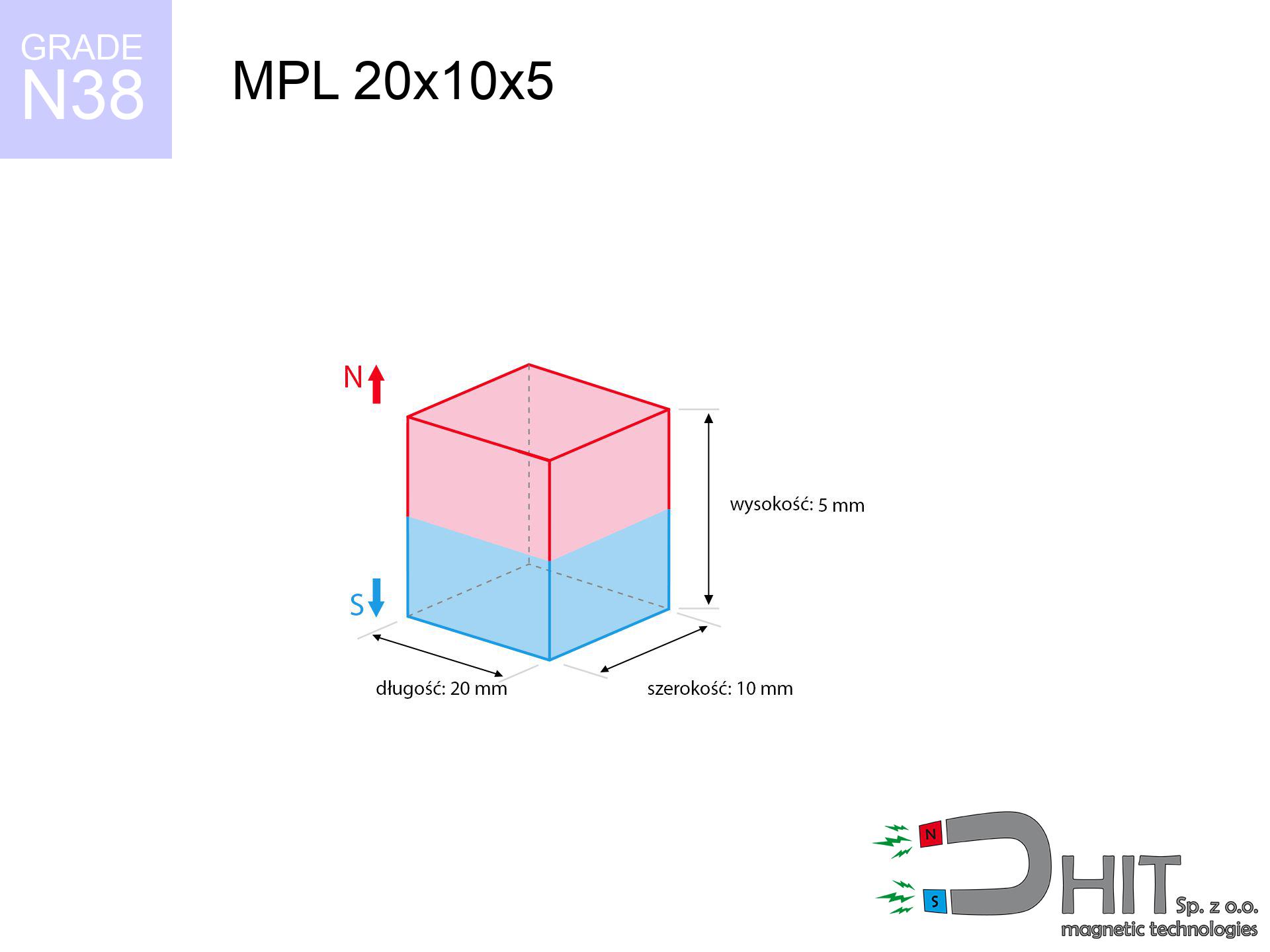
MPL 20x10x5 / N38 - lamellar magnet
lamellar magnet
Catalog no 020128
GTIN/EAN: 5906301811343
length
20 mm [±0,1 mm]
Width
10 mm [±0,1 mm]
Height
5 mm [±0,1 mm]
Weight
7.5 g
Magnetization Direction
↑ axial
Load capacity
6.15 kg / 60.31 N
Magnetic Induction
349.47 mT / 3495 Gs
Coating
[NiCuNi] Nickel
4.54 ZŁ with VAT / pcs + price for transport
3.69 ZŁ net + 23% VAT / pcs
bulk discounts:
Need more?
Give us a call
+48 888 99 98 98
if you prefer get in touch through
our online form
our website.
Force as well as appearance of a magnet can be analyzed with our
power calculator.
Orders submitted before 14:00 will be dispatched today!
Technical parameters - MPL 20x10x5 / N38 - lamellar magnet
Specification / characteristics - MPL 20x10x5 / N38 - lamellar magnet
| properties | values |
|---|---|
| Cat. no. | 020128 |
| GTIN/EAN | 5906301811343 |
| Production/Distribution | Dhit sp. z o.o. |
| Country of origin | Poland / China / Germany |
| Customs code | 85059029 |
| length | 20 mm [±0,1 mm] |
| Width | 10 mm [±0,1 mm] |
| Height | 5 mm [±0,1 mm] |
| Weight | 7.5 g |
| Magnetization Direction | ↑ axial |
| Load capacity ~ ? | 6.15 kg / 60.31 N |
| Magnetic Induction ~ ? | 349.47 mT / 3495 Gs |
| Coating | [NiCuNi] Nickel |
| Manufacturing Tolerance | ±0.1 mm |
Magnetic properties of material N38
| properties | values | units |
|---|---|---|
| remenance Br [min. - max.] ? | 12.2-12.6 | kGs |
| remenance Br [min. - max.] ? | 1220-1260 | mT |
| coercivity bHc ? | 10.8-11.5 | kOe |
| coercivity bHc ? | 860-915 | kA/m |
| actual internal force iHc | ≥ 12 | kOe |
| actual internal force iHc | ≥ 955 | kA/m |
| energy density [min. - max.] ? | 36-38 | BH max MGOe |
| energy density [min. - max.] ? | 287-303 | BH max KJ/m |
| max. temperature ? | ≤ 80 | °C |
Physical properties of sintered neodymium magnets Nd2Fe14B at 20°C
| properties | values | units |
|---|---|---|
| Vickers hardness | ≥550 | Hv |
| Density | ≥7.4 | g/cm3 |
| Curie Temperature TC | 312 - 380 | °C |
| Curie Temperature TF | 593 - 716 | °F |
| Specific resistance | 150 | μΩ⋅cm |
| Bending strength | 250 | MPa |
| Compressive strength | 1000~1100 | MPa |
| Thermal expansion parallel (∥) to orientation (M) | (3-4) x 10-6 | °C-1 |
| Thermal expansion perpendicular (⊥) to orientation (M) | -(1-3) x 10-6 | °C-1 |
| Young's modulus | 1.7 x 10⁴ | kg/mm² |
Physical simulation of the magnet - data
The following information represent the result of a physical simulation. Values are based on models for the material Nd2Fe14B. Operational performance might slightly differ from theoretical values. Treat these calculations as a reference point during assembly planning.
Table 1: Static force (pull vs distance) - characteristics
MPL 20x10x5 / N38
| Distance (mm) | Induction (Gauss) / mT | Pull Force (kg/lbs/g/N) | Risk Status |
|---|---|---|---|
| 0 mm |
3493 Gs
349.3 mT
|
6.15 kg / 13.56 pounds
6150.0 g / 60.3 N
|
warning |
| 1 mm |
3035 Gs
303.5 mT
|
4.64 kg / 10.23 pounds
4641.8 g / 45.5 N
|
warning |
| 2 mm |
2558 Gs
255.8 mT
|
3.30 kg / 7.27 pounds
3298.0 g / 32.4 N
|
warning |
| 3 mm |
2120 Gs
212.0 mT
|
2.26 kg / 4.99 pounds
2264.8 g / 22.2 N
|
warning |
| 5 mm |
1433 Gs
143.3 mT
|
1.03 kg / 2.28 pounds
1034.5 g / 10.1 N
|
low risk |
| 10 mm |
574 Gs
57.4 mT
|
0.17 kg / 0.37 pounds
166.1 g / 1.6 N
|
low risk |
| 15 mm |
267 Gs
26.7 mT
|
0.04 kg / 0.08 pounds
35.9 g / 0.4 N
|
low risk |
| 20 mm |
141 Gs
14.1 mT
|
0.01 kg / 0.02 pounds
10.1 g / 0.1 N
|
low risk |
| 30 mm |
52 Gs
5.2 mT
|
0.00 kg / 0.00 pounds
1.4 g / 0.0 N
|
low risk |
| 50 mm |
13 Gs
1.3 mT
|
0.00 kg / 0.00 pounds
0.1 g / 0.0 N
|
low risk |
Table 2: Vertical force (wall)
MPL 20x10x5 / N38
| Distance (mm) | Friction coefficient | Pull Force (kg/lbs/g/N) |
|---|---|---|
| 0 mm | Stal (~0.2) |
1.23 kg / 2.71 pounds
1230.0 g / 12.1 N
|
| 1 mm | Stal (~0.2) |
0.93 kg / 2.05 pounds
928.0 g / 9.1 N
|
| 2 mm | Stal (~0.2) |
0.66 kg / 1.46 pounds
660.0 g / 6.5 N
|
| 3 mm | Stal (~0.2) |
0.45 kg / 1.00 pounds
452.0 g / 4.4 N
|
| 5 mm | Stal (~0.2) |
0.21 kg / 0.45 pounds
206.0 g / 2.0 N
|
| 10 mm | Stal (~0.2) |
0.03 kg / 0.07 pounds
34.0 g / 0.3 N
|
| 15 mm | Stal (~0.2) |
0.01 kg / 0.02 pounds
8.0 g / 0.1 N
|
| 20 mm | Stal (~0.2) |
0.00 kg / 0.00 pounds
2.0 g / 0.0 N
|
| 30 mm | Stal (~0.2) |
0.00 kg / 0.00 pounds
0.0 g / 0.0 N
|
| 50 mm | Stal (~0.2) |
0.00 kg / 0.00 pounds
0.0 g / 0.0 N
|
Table 3: Vertical assembly (shearing) - vertical pull
MPL 20x10x5 / N38
| Surface type | Friction coefficient / % Mocy | Max load (kg/lbs/g/N) |
|---|---|---|
| Raw steel |
µ = 0.3
30% Nominalnej Siły
|
1.85 kg / 4.07 pounds
1845.0 g / 18.1 N
|
| Painted steel (standard) |
µ = 0.2
20% Nominalnej Siły
|
1.23 kg / 2.71 pounds
1230.0 g / 12.1 N
|
| Oily/slippery steel |
µ = 0.1
10% Nominalnej Siły
|
0.62 kg / 1.36 pounds
615.0 g / 6.0 N
|
| Magnet with anti-slip rubber |
µ = 0.5
50% Nominalnej Siły
|
3.08 kg / 6.78 pounds
3075.0 g / 30.2 N
|
Table 4: Material efficiency (substrate influence) - power losses
MPL 20x10x5 / N38
| Steel thickness (mm) | % power | Real pull force (kg/lbs/g/N) |
|---|---|---|
| 0.5 mm |
|
0.62 kg / 1.36 pounds
615.0 g / 6.0 N
|
| 1 mm |
|
1.54 kg / 3.39 pounds
1537.5 g / 15.1 N
|
| 2 mm |
|
3.08 kg / 6.78 pounds
3075.0 g / 30.2 N
|
| 3 mm |
|
4.61 kg / 10.17 pounds
4612.5 g / 45.2 N
|
| 5 mm |
|
6.15 kg / 13.56 pounds
6150.0 g / 60.3 N
|
| 10 mm |
|
6.15 kg / 13.56 pounds
6150.0 g / 60.3 N
|
| 11 mm |
|
6.15 kg / 13.56 pounds
6150.0 g / 60.3 N
|
| 12 mm |
|
6.15 kg / 13.56 pounds
6150.0 g / 60.3 N
|
Table 5: Thermal resistance (stability) - resistance threshold
MPL 20x10x5 / N38
| Ambient temp. (°C) | Power loss | Remaining pull (kg/lbs/g/N) | Status |
|---|---|---|---|
| 20 °C | 0.0% |
6.15 kg / 13.56 pounds
6150.0 g / 60.3 N
|
OK |
| 40 °C | -2.2% |
6.01 kg / 13.26 pounds
6014.7 g / 59.0 N
|
OK |
| 60 °C | -4.4% |
5.88 kg / 12.96 pounds
5879.4 g / 57.7 N
|
|
| 80 °C | -6.6% |
5.74 kg / 12.66 pounds
5744.1 g / 56.3 N
|
|
| 100 °C | -28.8% |
4.38 kg / 9.65 pounds
4378.8 g / 43.0 N
|
Table 6: Magnet-Magnet interaction (repulsion) - field range
MPL 20x10x5 / N38
| Gap (mm) | Attraction (kg/lbs) (N-S) | Sliding Force (kg/lbs/g/N) | Repulsion (kg/lbs) (N-N) |
|---|---|---|---|
| 0 mm |
15.04 kg / 33.17 pounds
4 923 Gs
|
2.26 kg / 4.98 pounds
2257 g / 22.1 N
|
N/A |
| 1 mm |
13.20 kg / 29.11 pounds
6 544 Gs
|
1.98 kg / 4.37 pounds
1980 g / 19.4 N
|
11.88 kg / 26.19 pounds
~0 Gs
|
| 2 mm |
11.36 kg / 25.03 pounds
6 069 Gs
|
1.70 kg / 3.76 pounds
1703 g / 16.7 N
|
10.22 kg / 22.53 pounds
~0 Gs
|
| 3 mm |
9.63 kg / 21.22 pounds
5 588 Gs
|
1.44 kg / 3.18 pounds
1444 g / 14.2 N
|
8.66 kg / 19.10 pounds
~0 Gs
|
| 5 mm |
6.71 kg / 14.78 pounds
4 664 Gs
|
1.01 kg / 2.22 pounds
1006 g / 9.9 N
|
6.03 kg / 13.30 pounds
~0 Gs
|
| 10 mm |
2.53 kg / 5.58 pounds
2 865 Gs
|
0.38 kg / 0.84 pounds
380 g / 3.7 N
|
2.28 kg / 5.02 pounds
~0 Gs
|
| 20 mm |
0.41 kg / 0.90 pounds
1 148 Gs
|
0.06 kg / 0.13 pounds
61 g / 0.6 N
|
0.37 kg / 0.81 pounds
~0 Gs
|
| 50 mm |
0.01 kg / 0.02 pounds
165 Gs
|
0.00 kg / 0.00 pounds
1 g / 0.0 N
|
0.00 kg / 0.00 pounds
~0 Gs
|
| 60 mm |
0.00 kg / 0.01 pounds
104 Gs
|
0.00 kg / 0.00 pounds
0 g / 0.0 N
|
0.00 kg / 0.00 pounds
~0 Gs
|
| 70 mm |
0.00 kg / 0.00 pounds
69 Gs
|
0.00 kg / 0.00 pounds
0 g / 0.0 N
|
0.00 kg / 0.00 pounds
~0 Gs
|
| 80 mm |
0.00 kg / 0.00 pounds
48 Gs
|
0.00 kg / 0.00 pounds
0 g / 0.0 N
|
0.00 kg / 0.00 pounds
~0 Gs
|
| 90 mm |
0.00 kg / 0.00 pounds
35 Gs
|
0.00 kg / 0.00 pounds
0 g / 0.0 N
|
0.00 kg / 0.00 pounds
~0 Gs
|
| 100 mm |
0.00 kg / 0.00 pounds
26 Gs
|
0.00 kg / 0.00 pounds
0 g / 0.0 N
|
0.00 kg / 0.00 pounds
~0 Gs
|
Table 7: Hazards (implants) - precautionary measures
MPL 20x10x5 / N38
| Object / Device | Limit (Gauss) / mT | Safe distance |
|---|---|---|
| Pacemaker | 5 Gs (0.5 mT) | 7.5 cm |
| Hearing aid | 10 Gs (1.0 mT) | 6.0 cm |
| Mechanical watch | 20 Gs (2.0 mT) | 4.5 cm |
| Phone / Smartphone | 40 Gs (4.0 mT) | 3.5 cm |
| Car key | 50 Gs (5.0 mT) | 3.5 cm |
| Payment card | 400 Gs (40.0 mT) | 1.5 cm |
| HDD hard drive | 600 Gs (60.0 mT) | 1.0 cm |
Table 8: Dynamics (cracking risk) - warning
MPL 20x10x5 / N38
| Start from (mm) | Speed (km/h) | Energy (J) | Predicted outcome |
|---|---|---|---|
| 10 mm |
29.36 km/h
(8.16 m/s)
|
0.25 J | |
| 30 mm |
50.03 km/h
(13.90 m/s)
|
0.72 J | |
| 50 mm |
64.58 km/h
(17.94 m/s)
|
1.21 J | |
| 100 mm |
91.32 km/h
(25.37 m/s)
|
2.41 J |
Table 9: Surface protection spec
MPL 20x10x5 / N38
| Technical parameter | Value / Description |
|---|---|
| Coating type | [NiCuNi] Nickel |
| Layer structure | Nickel - Copper - Nickel |
| Layer thickness | 10-20 µm |
| Salt spray test (SST) ? | 24 h |
| Recommended environment | Indoors only (dry) |
Table 10: Electrical data (Flux)
MPL 20x10x5 / N38
| Parameter | Value | SI Unit / Description |
|---|---|---|
| Magnetic Flux | 7 031 Mx | 70.3 µWb |
| Pc Coefficient | 0.42 | Low (Flat) |
Table 11: Physics of underwater searching
MPL 20x10x5 / N38
| Environment | Effective steel pull | Effect |
|---|---|---|
| Air (land) | 6.15 kg | Standard |
| Water (riverbed) |
7.04 kg
(+0.89 kg buoyancy gain)
|
+14.5% |
1. Wall mount (shear)
*Warning: On a vertical wall, the magnet holds only ~20% of its nominal pull.
2. Steel thickness impact
*Thin metal sheet (e.g. computer case) drastically weakens the holding force.
3. Power loss vs temp
*For standard magnets, the critical limit is 80°C.
4. Demagnetization curve and operating point (B-H)
chart generated for the permeance coefficient Pc (Permeance Coefficient) = 0.42
The chart above illustrates the magnetic characteristics of the material within the second quadrant of the hysteresis loop. The solid red line represents the demagnetization curve (material potential), while the dashed blue line is the load line based on the magnet's geometry. The Pc (Permeance Coefficient), also known as the load line slope, is a dimensionless value that describes the relationship between the magnet's shape and its magnetic stability. The intersection of these two lines (the black dot) is the operating point — it determines the actual magnetic flux density generated by the magnet in this specific configuration. A higher Pc value means the magnet is more 'slender' (tall relative to its area), resulting in a higher operating point and better resistance to irreversible demagnetization caused by external fields or temperature. A value of 0.42 is relatively low (typical for flat magnets), meaning the operating point is closer to the 'knee' of the curve — caution is advised when operating at temperatures near the maximum limit to avoid strength loss.
Material specification
| iron (Fe) | 64% – 68% |
| neodymium (Nd) | 29% – 32% |
| boron (B) | 1.1% – 1.2% |
| dysprosium (Dy) | 0.5% – 2.0% |
| coating (Ni-Cu-Ni) | < 0.05% |
Ecology and recycling (GPSR)
| recyclability (EoL) | 100% |
| recycled raw materials | ~10% (pre-cons) |
| carbon footprint | low / zredukowany |
| waste code (EWC) | 16 02 16 |
Other products

![SM 32x225 [2xM8] / N52 - magnetic separator](https://cdn3.dhit.pl/graphics/products/sm-32x225-2xm8-zix.jpg "SM 32x225 [2xM8] / N52 - magnetic separator")


Pros as well as cons of neodymium magnets.
Benefits
- Their magnetic field is maintained, and after approximately 10 years it decreases only by ~1% (according to research),
- They have excellent resistance to magnetism drop as a result of opposing magnetic fields,
- In other words, due to the shiny surface of silver, the element gains visual value,
- They show high magnetic induction at the operating surface, which affects their effectiveness,
- Due to their durability and thermal resistance, neodymium magnets are capable of operate (depending on the form) even at high temperatures reaching 230°C or more...
- Thanks to flexibility in shaping and the ability to adapt to individual projects,
- Huge importance in future technologies – they are utilized in data components, motor assemblies, advanced medical instruments, also technologically advanced constructions.
- Compactness – despite small sizes they generate large force, making them ideal for precision applications
Disadvantages
- They are fragile upon too strong impacts. To avoid cracks, it is worth securing magnets in special housings. Such protection not only shields the magnet but also improves its resistance to damage
- We warn that neodymium magnets can lose their strength at high temperatures. To prevent this, we recommend our specialized [AH] magnets, which work effectively even at 230°C.
- Due to the susceptibility of magnets to corrosion in a humid environment, we suggest using waterproof magnets made of rubber, plastic or other material stable to moisture, in case of application outdoors
- Limited possibility of producing nuts in the magnet and complex forms - preferred is casing - magnetic holder.
- Health risk related to microscopic parts of magnets can be dangerous, when accidentally swallowed, which becomes key in the context of child health protection. Furthermore, small elements of these products can complicate diagnosis medical after entering the body.
- With large orders the cost of neodymium magnets is a challenge,
Holding force characteristics
Maximum holding power of the magnet – what affects it?
- using a base made of mild steel, functioning as a ideal flux conductor
- with a thickness minimum 10 mm
- with an ground contact surface
- under conditions of no distance (metal-to-metal)
- for force applied at a right angle (pull-off, not shear)
- at temperature room level
Determinants of lifting force in real conditions
- Gap between surfaces – even a fraction of a millimeter of separation (caused e.g. by veneer or unevenness) significantly weakens the magnet efficiency, often by half at just 0.5 mm.
- Pull-off angle – remember that the magnet has greatest strength perpendicularly. Under sliding down, the holding force drops significantly, often to levels of 20-30% of the maximum value.
- Plate thickness – too thin steel does not close the flux, causing part of the flux to be lost to the other side.
- Metal type – not every steel attracts identically. Alloy additives weaken the interaction with the magnet.
- Surface structure – the smoother and more polished the plate, the larger the contact zone and higher the lifting capacity. Unevenness acts like micro-gaps.
- Operating temperature – NdFeB sinters have a negative temperature coefficient. When it is hot they are weaker, and in frost gain strength (up to a certain limit).
Lifting capacity was measured using a polished steel plate of suitable thickness (min. 20 mm), under perpendicular detachment force, however under attempts to slide the magnet the holding force is lower. In addition, even a small distance between the magnet’s surface and the plate decreases the holding force.
Warnings
Powerful field
Before starting, check safety instructions. Uncontrolled attraction can destroy the magnet or hurt your hand. Be predictive.
Electronic devices
Intense magnetic fields can destroy records on credit cards, hard drives, and other magnetic media. Maintain a gap of at least 10 cm.
Warning for allergy sufferers
Certain individuals suffer from a sensitization to Ni, which is the standard coating for neodymium magnets. Prolonged contact might lead to skin redness. We recommend wear safety gloves.
Keep away from children
NdFeB magnets are not intended for children. Swallowing multiple magnets can lead to them pinching intestinal walls, which constitutes a direct threat to life and necessitates immediate surgery.
Precision electronics
An intense magnetic field negatively affects the functioning of magnetometers in phones and GPS navigation. Do not bring magnets near a smartphone to avoid damaging the sensors.
Physical harm
Pinching hazard: The pulling power is so great that it can result in hematomas, pinching, and even bone fractures. Protective gloves are recommended.
Machining danger
Combustion risk: Neodymium dust is highly flammable. Avoid machining magnets without safety gear as this risks ignition.
Implant safety
Patients with a heart stimulator must keep an safe separation from magnets. The magnetic field can stop the functioning of the life-saving device.
Material brittleness
Despite the nickel coating, the material is delicate and cannot withstand shocks. Do not hit, as the magnet may crumble into sharp, dangerous pieces.
Power loss in heat
Monitor thermal conditions. Heating the magnet above 80 degrees Celsius will permanently weaken its magnetic structure and strength.
Tabela kosztu i czasu dostawy
Płatność przed wysyłką:

GLS kurier
Przesyłka będzie u Ciebie za 2-3 dni
14.99 ZŁ

InPost Paczkomaty 24/7
Przesyłka będzie u Ciebie za 1-2 dni
12.30 ZŁ
Płatność przy odbiorze (pobranie):
GLS kurier
Przesyłka będzie u Ciebie za 1-2 dni
23.00 ZŁ
Rate the product
Your rating